1
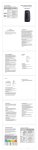
7. Specification Model Motor Power Rating MR 400 MR 600 MR 1000 1/4 HP 300KG 1/2 HP 550KG 1HP 1000KG Capacity 750VA/450W 1KVA/600W 1.5KVA/900W OUTPUT Start Cap. 2KVA 3KVA 5KVA Voltage Same as input nominal Regulation V rms ±5% Frequency 50/60 HZ Waveform PWM Stepwave Voltage 110/220V Selectable INPUT Frequency 50/60 HZ ±3 HZ Battery Volt. 24VDC 24VDC 48VDC BATTERY Spec. / pcs 12V8AH / 2pcs 12V7AH/ 4pcs 12V8AH/ 4pcs Type Lead-acid Maintenance Free Line→Inv. 135V, Inv.→Line 130V (110V) PROTECTION Over Voltage Line→Inv. 270V, Inv.→Line 260V (220V) Under Line→Inv. 88V, Inv.→Line 93V (110V) Voltage Line→Inv. 176V, Inv.→Line 186V (220V) Surge Filter & Surge Suppression meet IEEE-587, Cat. A; Noise Varistor clamping 150J.Response greater than 20dB & over 1MHZ for Common & Transverse Modes Overload Fuse & Current Limited & Cut-off INDICATOR Short Circuit Low Battery Audible SHUTTER MOTOR DOOR UPS SYSTEM MR400 / MR600 / MR1000 Fuse & Current Limited & Cut-off Two stages, no battery drain after battery cut-off Alarm; AC Failure, Low Battery and Overload Visible AC SW LED; AC On→Light; AC Off→Dark 220V LED; 220V→Light; 110V→Dark CPU LED; Normal→Slow; Start Timer→Fast 115V position→110~120V system SELECTION 115V/230V 230V position→220~240V system Without AC Present, Force UPS by Pushing Switch COLD START Install a Light. It will Light while AC Failure EMERGENCY LIGHT Temperatur 0 – 40 degree C NVIROMENT e Humidity 0 – 90 % Non-condensing 275 x 250 x 150 340 x 310 x 150 340 x 310 x 150 MECHANICAL WxHxD mm Weight 15.0 KGS 20.0 KGS 25.0 KGS USER MANUAL 6. Maintenance IMPORTANT SAFETY INSTRUCTION ‧ This manual contains important instructions that should be followed during installation and maintenance of the U.P.S. and batteries. 6.1 Operation The UPS system contains no user-serviceable parts. If the battery service life (3 - 5 years at 25 °C ambient temperature) has been exceeded, the batteries must be exchanged. Please consult your dealer in this case. ‧ Read this manual thoroughly before operation. ‧ If apparent damage to the unit is found upon unpacking, return the unit to your dealer for proper handling. ‧ Technical service to the unit should be done by an authorized personnel. Unauthorized service by the users will void the WARRANTY. ‧ The U.P.S. is designed for 115V/230V equipments use. Please make sure the 115V/230V selection switch is on right position before using it. ‧ Keep this unit away from wet areas. ‧ Do not leave the unit in direct sunlight. ‧ While cleaning, do not apply any chemical solvent to the unit. Dry cloth is preferred to avoid any dripping into the circuit. ‧ This unit is intended for installation in a temperature-controlled, indoor area free of conductive contaminants SAVE THESE INSTRUCTIONS 6.2 Storage If the batteries are to be stored in temperate climatic zones, they should be charged every three months for 8 hours. You should shorten the charging intervals to two months at locations subject to high temperatures. 5. Troubleshooting If the UPS system does not operate correctly, please attempt to solve the problem using the table below. Problem Possible cause Remedy No output voltage On/Off switch in Set the On/Off switch to or no indication or position “0” (OFF) position “1” (ON) UPS remains on battery mode even if the AC line normal and main switch ON Line-side fuse of Check the load. If an UPS system overload has occurred, defective reduce the number of loads and then check the line-side fuse and exchange it if necessary by pushing it. No input voltage Check wall receptacle, check input power cord UPS system issues UPS system Reduce the number of acoustic alarm overload loads connected to the every second when UPS output normal mode Stored energy time Batteries not fully Charge the batteries for less than nominal charged / batteries at least 4 hours. Check value or no stored defective capacity. If the problem energy time still persists, please consult your dealer. Please have the following information ready at hand before calling the After-Sales Service Department: 1. Model number, serial number 2. Date on which the problem occurred 3. Detailed description of the problem Contents 1. Introduction-------------------------------------------------------4 2. Installation and Operation-------------------------------------5 3. Layout & Description-------------------------------------------6 4. Indicators and Operating Controls--------------------------9 5. Troubleshooting------------------------------------------------10 6. Maintenance-----------------------------------------------------11 7. Specification-----------------------------------------------------12 1. Introduction The super UPS MR -Series is a newly developed Line-Interactive system with simulated sine wave for uninterruptible power supply. The MR-Series UPS is design for home use purpose. It can be used for the home electrical appliances even motor appliances. The MR-Series UPS also with a emergency light outlet, user can install a light or bulb instead of the emergency light or emergency exit light. Its features as below, ◎Easy Installation and Repair ◎Cold Start Function ◎Powerful Start Capacity ◎Smart Battery Testing ◎Manual Selection for 110V or 220V System ◎UPS + Emergency Light Function ◎Over 32 Hours Standby time ◎Smart Overload and Short Circuit Protection ◎Low Battery Voltage Alarm ◎Low Battery Cut-off Automatically ◎No Load Automatic Shutdown by Timer ◎Auto Transfer to Battery Mode by Timer ◎Option for AVR Function ◎Option for External Battery Bank 4. Indicators and Operating Controls Switches/ buttons Function 1. Switches the UPS system on and off: On/Off switch (on front panel) DC start UPS system is switched on if switch is on “1” position, UPS system is switched off if switch is on “0” position. 1. Starts the UPS system from the batteries if the AC power has failed. In this case, the DC start switch must also be pressed after switching the UPS system on with the On/Off switch. In this case, do not switch on the loads connected to the output of the UPS system until approx. 20 seconds after the UPS system has been started. 2. Switches off the audible alarm in battery mode CPU state indicator (light-emittin g diode/LED) Indicates the status of the CPU: 115V/230V switch state indicator (light-emittin g diode/LED) The following information is displayed: Operating state indicator (buzzer/BZ) Indicates the status of the UPS system: Normal : Refer to page 4, #3 CPU Run LED ATTBM Activity: Refer to page 4, #3 CPU Run LED NLAS Activity: Refer to page 4, #3 CPU Run LED LED lights, switch is on 230V position. LED darks, switch is on 115V position. operation via mains (BZ silence) operation via batteries (beeping every 4 seconds) operation via batteries low stage (beeping every half second) #8 AC Inlet This is to be connected with the enclosed AC power cord for plugging into the wall receptacle. #9 AC Input fuse This is to disconnect line input to protect outlets from over load or short circuit. A spare fuse is also enclosed for possible replacement purpose. #10 External Battery Socket (option) This is to be connected to the external battery pack to extend the backup time. Please make sure the external battery voltage is same as the U.P.S. specification. For examples, D750/D1000 is 24V and D1500 is 48V. #11 DIP Switch (on main PCB, Inside the Case) This is to setting the Green Function, ATTBM Function, and NLAS Function. Green Function Setting: ON→Disable; OFF→Enable ATTBM Timer Setting: ON→10 sec.; OFF→30 days NLAS Timer Setting: ON→5 min. ; OFF→Disable Remark: ATTBM: Auto Transfer to Battery Mode by Timer NLAS: No Load Automatic Shutdown by Timer. (Option for a remote controller) Green Function: Enlarge Stand-by Time and Enable Powerful Start Capacity. #12 System Voltage Selection Switch (Inside the Case) This is to select the system operating voltage. Please make sure the equipment (motors) you connect to the U.P.S. are used for 110~120V or 220V~240V power system. The wrong position will be damaged the equipment (motors). 2. Installation and Operation 1) Inspect the packaging carton and its contents for damage. Please inform the transport agency immediately should you find signs of damage. Please keep the packaging in a safe place for future use. 2) Connect the UPS system to a wall receptacle with a VDE-tested, CE-marked or UL-marked mains cable (e.g. the mains cable of your computer). 3) Fully charge the batteries of the UPS system by leaving the UPS system connected to the mains for 4 hours. You can also use the UPS system directly without charging it, but the stored energy time may then be shorter than the nominal value specified. Note: The UPS system charges the batteries automatically as soon as it is connected to a wall receptacle and the On/Off switch is set to the ON. 4) Connect your computer to the UPS output sockets by using the enclosed power cord. Caution! 1. Do not connect appliances or equipments that would overload the UPS system to the UPS output sockets. 2. Please make sure that the position of UPS 115V/230V SW is on the right position. For samples, if your AC power is 110~120V system, please place the SW on 115V position; if your AC power is 220~240V system, please place the SW on 230V position 5) Set the On/Off switch on the unit right panel to position ON. 6) Test the UPS system by disconnecting the input power cord of the UPS system from the wall receptacle. Caution! The output sockets of the UPS system may still be electrically live even if the mains supply has been disconnected or the mains cable has been disconnected. 3. Layout & Description Right, left and inside view, MR-400, MR-600, MR-1000 #1 Power Switch This is to control the ON/OFF of the U.P.S. #2 DC Start Switch This is to start the UPS system from the batteries if the main power has failed. In this case, the Reset button must also be pressed after switching the UPS system on with the On/Off switch. #3 CPU Run LED This is to show the status of CPU. Status Normal — ATTBM – LED — — — — — – – – – — — — — – – – – – NLAS ---- -----ATTBM: Auto Transfer to Battery Mode by Timer NLAS: No Load Automatic Shutdown by Timer -- — – -- — – -- #4 System Voltage LED This is to show the 115V/230V switch position, when LED light indicating 115V/230V switch is on 230V position. Please make sure the equipments (motors) you connect to the U.P.S. are used for 220V~240V power system. The wrong position will be damaged the equipments (motors). #5 AC Outlet NEMA These are to be connected to the equipments (motors) that will be protected by the U.PS. #6 AC Outlet IEC This is also to be connected to the equipments (motors) that will be protected by the U.PS. #7 Emergency Light Outlet This is to be connected to the emergency light (only a light is enough, don’t use the standard emergency light). When AC power normal the outlet will no power output. But when AC fail the outlet will be provide AC power to the emergency light.