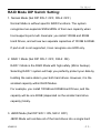
1
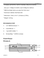
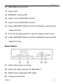
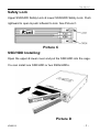
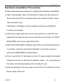
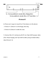
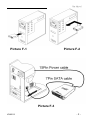
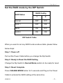
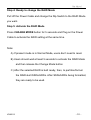
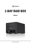
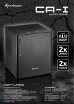
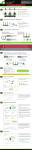
User Manual
User Manual
A-DATA XPG 3.5” SSD RAID Enclosure
Description:
The RAID Enclosure is a complete RAID solution through the use of
two 2.5" SATA hard disks mounted on one mini 3.5" form factor drive
cage. It is used as a standard 2.5" SSD/HDD with mirroring capability
(RAID 1). By mirroring technique, it maintains data in two disk drives
simultaneously and securely. If one drive fails, it automatically switches
operations to the functional drive and after changed a new hard drive
the data is mirroring back.
Features:
* Interface: SATA-I/II
* LED indication for Working and Failure.
* The dimensions match exactly as a standard 3.5" bay.
* Energy saving on using 2.5” SSD or HDD.
* For the use on desktop, server case, rack mount chassis that is
with 3.5” form factor space.
V090513
-1-
User Manual
* Complies with SATA-I, SATA-II interface. Maximum transfer
rate up to 1.5Gbps for SATA-I and 3.0Gbps for SATA-II.
* SSD Auto Eject when you open the front cover.
* Aluminum material, best heat sink.
* Dimension: 148.2 x 101.7 x 25.8mm (L*W*H)
* Weight: 0.23 kg
Accessory List:
1.
3.5” RAID Enclosure * 1
2.
User Manual * 1
3.
7 pin SATA Cable * 1
4.
Screws Bag * 1 (With 4 screws)
Front Panel:
Picture A
V090513
-2-
User Manual
A1 : SSD/HDD 0 Access LED
A2 : Power LED
A3: SSD/HDD 1 Access LED
A4 : Upper cover & SSD/HDD extractor
A5 : Lower cover & SSD/HDD extractor
A6 : Upper SSD/HDD Safety Lock (Push rightward to open & push
leftward to lock)
A7 : Push the rise high position to open the upper & lower cover
A8 : Lower SSD/HDD Safety Lock (Push rightward to open & push
leftward to lock)
Rear Panel:
B1 : SATA 15pin power connector
B2 : SATA 7pin data connector for SSD/HDD 0
B3 : RAID mode configuration DIP switch
B4 : Change mode button
V090513
-3-
User Manual
LED Table
Check the following to see the LED Indicator Table.
Action
Light On
Light Off
Light On
Flash
Light On
Light Off
Light On
Light Off
Light On
Flash
SSD/HDD 0 Access LED Indicator (A1)
Message
Hard Drive 0 Installed
Hard Drive 0 uninstalled
Hard Drive 0 Fail
Hard Drive 0 Access
Power LED Indicator (A2)
Power is ON
Power is OFF
SSD/HDD 1 Access LED Indicator (A3)
Hard Drive 1 Installed
Hard Drive 1 uninstalled
Hard Drive 0 Fail
Hard Drive 1 Access
Color
Blue
No
Red
Blue
Blue
No
Blue
No
Red
Blue
The following is the special case LED table.
LED Indicator in special case
Message
LED
Both Hard Drives installed
A1/A2
without cable connection
Color / Action
Blue/Light on
The following is the LED Indicator in RAID modes.
RAID
Mode
RAID 1
RAID 1
RAID 1
RAID 1
JBOD
JBOD
RAID 0
V090513
RAID Mode LED Indicator
Message
LED
Reading
Writing
SSD/HDD 0 Rebuilding
SSD/HDD 1 Rebuilding
SSD/HDD 0 Access
SSD/HDD 1 Access
Access
A1
A1/A3
A1
A3
A1
A3
A1/A3
Color / Action
Blue/Flash
Blue/Flash
Blue & Red/Flash
Blue & Red/Flash
Blue/Flash
Blue/Flash
Blue/Flash
-4-
User Manual
Safety Lock
Upper SSD/HDD Safety Lock & Lower SSD/HDD Safety Lock. Push
rightward to open & push leftward to lock. See Picture C.
Picture C
SSD/HDD Installing:
Open the upper & lower cover and put the SSD/HDD into the cage.
You can install one SSD/HDD or two SSDs/HDDs.
Picture D
V090513
-5-
User Manual
Hardware Installation Procedures
Please follow below procedures to complete the hardware installation:
1) Open the package, take out the product, make sure the product is
brand new and all the necessary parts are included (Please check
with Accessory List).
If damage or shortage occurred, please contact your distributor
or where you bought.
2) Unlock the upper and lower covers (see picture C), push the lock
rightward and open the two covers and then, put the two 2.5" SATA
SSDs/HDDs into the box (See Picture D).
3) After both SSDs/HDDs installed, push both covers back like picture
C and then, push the lock button leftward to lock both covers to
secure the SSDs/HDDs inside properly.
4) Then, mount the 3.5” enclosure on the 3.5” space using the included
screws to mount it on the device (desktop, case… etc.) and make all
the cable connected properly and it is ready for use.
5) See the drawing of the two ways to mount the 3.5” enclosure on the
Device (See Picture E).
V090513
-6-
User Manual
Picture E
6) There are 2 ways to mount the 3.5”enclosure on the device:
-- Picture F-1) Mount it on the floppy drive bay
-- Picture F-2) Mount it inside the case
7) Connect the 3.5” enclosure with PC via 15pin SATA power cable
(from Power Supply) and 7pin SATA cable (using included cable).
(See Picture F-3)
V090513
-7-
User Manual
Picture F-1
Picture F-2
Picture F-3
V090513
-8-
User Manual
Set the RAID mode by the DIP Switch:
RAID Config
RAID Status
1
2
Normal
OFF
OFF
RAID 1
OFF
ON
JBOD
ON
OFF
RAID 0
ON
ON
DIP Switch Table
When you want to set any RAID mode as above table, please follow
below steps:
Step 1: Power off
Pull out the Power Cable before you change the Dip Switch.
Step 2: Ready to Reset the RAID Setting
Change the Dip Switch to Normal Mode position to be ready for reset.
Step 3: Reset Complete.
Press CHANGE MODE button for 5 seconds and Plug on the Power
Cable to activate the RAID setting at the same time.
V090513
-9-
User Manual
Step 4: Ready to change the RAID Mode
Pull off the Power Cable and change the Dip Switch to the RAID Mode
you want.
Step 5: Activate the RAID Mode
Press CHANGE MODE button for 5 seconds and Plug on the Power
Cable to activate the RAID setting at the same time.
Note:
A) If present mode is in Normal Mode, users don’t need to reset.
B) Users should wait at least 5 seconds to activate the RAID Mode
and then release the Change Mode button
C) After the selected RAID is built ready, then, to partition/format
the RAID-built SSDs/HDDs. After SSDs/HDDs being formatted,
they are ready to be used.
V090513
- 10 -
User Manual
RAID Mode DIP Switch Setting:
1. Normal Mode (Set DIP SW-1: OFF, SW-2: OFF)
Normal Mode is without specific RAID Functions. The system
recognizes two separate SSDs/HDDs of their own capacity when
host supports port-multi. Example: you install 100GB and 80GB
Hard Drives, and will see two separate capacities of 100GB & 80GB.
If port-multi is not supported, it can recognize one HDD only.
2. RAID 1 Mode (Set DIP SW-1: OFF, SW-2: ON)
RAID 1 Mode is the RAID Mode with high safety (Mirror backup).
Selecting RAID 1 system will help you perfectly protect your data by
building the same data in your both hard drives. However, it is the
smallest capacity within RAID Modes.
For example, you install 100GB and 80GB Hard Drives, and the
capacity will be one 80GB (depended on the smaller hard drive
capacity) totally.
3. JBOD Mode (Set DIP SW-1: ON, SW-2: OFF)
JBOD Mode will combine all of the hard drives into a single hard
V090513
- 11 -
User Manual
drive with larger capacity.
For example, you install 100GB and 80GB Hard Drives, and the
capacity will be in one 180GB (100GB+80GB) totally.
4. RAID 0 Mode (Set DIP SW-1: ON, SW-2: ON)
RAID 0 Mode is the fastest RAID Mode. Advantage of RAID 0 is to
achieve high performance by accumulating each individual hard
disk performance. However, if any one hard disk gets defective,
information stored in this RAID 0 will be invalid. RAID 0 Mode will
just make use of the same size disk space in each hard disk
condition.
For Example: You install 100GB and 80GB Hard Drives, and the
capacity will be 160GB (80GB+80GB) totally.
V090513
- 12 -
User Manual
Trouble Shooting
A) Why can’t I open the panel cover?
Please check the Safety Lock is at UNLOCK position.
B) Can I install or uninstall the Hard Drive anytime?
We suggest you to turn off PC before your installation.
C) Why can’t I see the Hard Drive in “My Computer” after I installed?
Please check the LED Table to see if it’s normal. If the LED is in
normal situation. Then Please check if the SSD/HDD is formatted or
not.
D) Can I install SSD * 1 and HDD * 1, and work well?
Yes, it’ll work fine and the performance is depended on the
SSD/HDD that you installed.
E) What’s the default RAID mode when I get the product?
The default RAID mode is Normal Mode. And please check the
RAID Mode setting steps to change the RAID Mode you want.
F) Why can’t I change the RAID Mode?
Please follow the RAID Mode setting step by step. And confirm if the
V090513
- 13 -
User Manual
CHANGE MODE button pressing while the power cable is
connecting.
H) Why is the capacity small in RAID 1?
The RAID 1 is the safest RAID Mode. The RAID enclosure needs
the same capacity in both Hard Drives to mirror the data. Though
the capacity will be smallest, the data can rebuild automatically in
case one of your hard drive is broken.
V090513
- 14 -
User Manual
Notice:
1. Hot-plug function depends on your PC system. Generally, internal
SATA device does not support hot-plug function. Some e-SATA
devices support but also depend on the motherboard driver.
If you are not clear that your PC system supports or not, please do
not change your SSD or HDD as the PC is working.
Or your PC may hang up or damage your storage device.
2. During file saving, please do not disconnect the storage device
even if your PC supports hot-plug.
Disclaimer
All the information in this document is subject to change without prior notice. The
manufacturer makes no representations or any warranties regarding the Contents of this
manual. The information contained in this manual is provided for the general use by the
customers. No part of this document may be reproduced or transmitted in any form by any
means without the express written permission of the manufacturer. All brand names and
product names used in this document are trademarks or registered trademarks of their
respective holders.
V090513
- 15 -