1
16ch DIGITAL VIDEO RECORDER
INSTRUCTION MANUAL
Before connecting, operating or adjusting this product,
Read this instruction booklet carefully and
completely
Digital Video Recorder
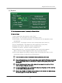
- Helpful Tips 1. System power should be off when installing or removing external storage devices.
For the purpose of data protection and safe system operation, make sure that the system
power is turned off before installing or removing external storage devices such as IEEE1394
HDD, USB FDD device or portable HDD.
When rebooting DVR system, turn off and on the external device(IEEE1394) for external
device initialization.
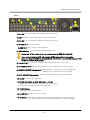
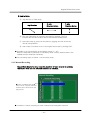
2. Check the color marked on the screen.
For user convenience, channel mode is marked for each channel.
WHITE Mark : Video Loss
RED Mark : Record Mode
BLUE Mark : Live Mode
GREEN Mark : Event Record Mode(Alarm, Motion).
3. Be cautious when recording.
Set the system time and date, and check schedule settings prior to record.
Record button at the front functions depending on schedule and record setting conditions.
4. High quality view.
If using composite VBS monitor, unset VGA Monitor Output under System Setup / Video
Output for high quality view.
If using VGA monitor, press STOP and DISPLAY button at the same time and hold it
for 3 seconds for high quality view.
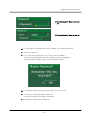
5. System password
Set password under System / Administration / Admin. Password, check Use Password
box to enable system password. This will prompt for password when record or menu button
is pressed.
Do not expose or forget the password.
6. KEY LOCK function
Enable Lock Front from administration menu to disable all buttons other than Setup button.
- Refer to manual for details.-
-- 2 --
Digital Video Recorder
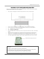
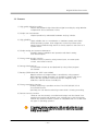
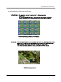
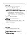
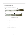
Instructions and tips for installing and removing internal HDDs
Removing or installing HDD(s) may cause to delete data in HDD(s) and therefore please
contact service center prior to this operation.
•
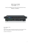
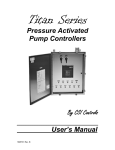
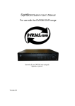
The system is designed to install 4 internal HDDs at most as shown below.
•
•
•
•
•
•
P1 slot : Slot for connection to Primary Master, Slave HDD or both together.
P2 slot : Slot for connection to Secondary Master, Slave HDD or both together.
C1 : Connects to P1 or P2 slot on board.
C2 : Connects to Slave HDD.
C3 : Connects to Master HDD.
For a removable HDD, connect C2 to P2 slot and set the HDD as a slave. (Secondary
Slave)
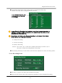
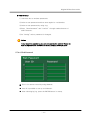
HDDs should be connected in the following order and expressed as written below.
Cable for P1: ① IDE(PM)/Primary Master HDD, ② IDE(PS) /Primary Slave HDD
Cable for P2: ③ IDE(SM)/Secondary Master HDD, ④IDE(RM)/Secondary Slave HDD
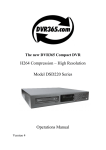
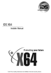
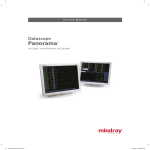
For HDDs’ Master/Slave settings, refer to HDDs’ manual that stuck on top of HDDs.
•
•
•
•
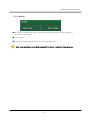
Master/slave setting instruction
WARNING
1.
2.
3.
4.
Install or remove HDDs in the order as shown above.
Deleting a HDD will also delete all data in HDD(s) numbered after deleting HDD.
Using other HDDs’ may cause HDDs’ data corruption or deletion.
Use HDD with encouraged specifications. (Maker,Capacity,Type)
-- 3 --
Digital Video Recorder
WARNING : Changes or modifications not expressly approved by
the manufacturer could void the user’s authority to
operate the equipment.
FCC WARNING : This equipment may generate or use radio frequency energy.
Changes or modifications to this equipment may cause harmful interference unless
the modifications are expressly approved in the instruction manual. The user could
lose the authority to operate this equipment if an unauthorized change or modification
is made.
INFORMATION TO THE USER
This equipment has been tested and found to comply with the limits for a Class A
digital device, pursuant to part 15 of the FCC Rules. These limits are designed to
provide reasonable protection against harmful interference when the equipment is
operated in a commercial environment. This equipment generates, uses, and can
radiate radio frequency energy and, if not installed and used in accordance with
the instruction manual, may cause harmful interference to radio communications.
Operation of this equipment in a residential area is likely to cause harmful
interference in which case the user will be required to correct the interference at
his own expense. Changes or modifications to this equipment may cause harmful
interference unless the modifications are expressly approved in the instruction
manual. The user could lose the authority to operate this equipment if an unauthorized
change or modification is made.
This Class (A) digital apparatus meets all requirements of the Canadian interference
Causing Equipment Regulations.
Cet appareil numerique de la classe A respecte toutes les exigencces du Reglement
Sur materiel brouilleur du Canada.
THE EQUIPMENT COMPLIES WITH THE REGULATION OF FCC CRF 47 PART 15,
SUBPART B, CLASS A. THIS TEST REPORT CONTAINS ONLY THE RESULTS OF
A SINGLE TEST OF THE SAMPLE SUPPLIED FOR THE EXAMINATION.
CE WARNING
This is a Class A product. In a domestic environment this product may cause radio
interference in which case the user may be required to take adequate measures.
-- 4 --
Digital Video Recorder
-CONTENTS1. Safety Information ------------------------------------------------------- 8
2. Part Names and Features -------------------------------------------------- 9
2.1 Basic Organization of DVR System ---------------------------------------- 9
2.2 Features ---------------------------------------------------------- 10
2.3 Part Name and Description -------------------------------------------- 12
2.4 Power and Battery Setup ---------------------------------------------- 15
3. Explanation and Application ----------------------------------------------- 16
3.1 Basic Schematic of the DVR System -------------------------------------- 16
3.1.1 Basic Schematic ------------------------------------------------ 16
3.1.2 Explanation of Schematic ------------------------------------------ 17
3.2 Basic Connections -------------------------------------------------- 18
3.3 Pan/Tilt Camera Connection and Control ---------------------------------- 19
3.3.1 Pan/Tilt Camera Organization --------------------------------------- 19
3.3.2 How to Setup --------------------------------------------------3.3.3 Control (RS-485) -----------------------------------------------3.4 External Product Connections and Application -----------------------------3.4.1 External Product Connection of SENSOR INPUT Application ---------------3.4.2 External Product Connection of ALARM OUTPUT Application --------------3.5 Installation and Application for Network Interface ---------------------------3.5.1 Connection and Installation for Remote Control --------------------------
20
20
21
21
22
23
23
3.5.2 How to Connect by Domain ---------------------------------------3.5.3 How to Setup Static IP -------------------------------------------3.5.4 Network Setup -------------------------------------------------3.5.5 Network with IP Share --------------------------------------------3.6 Application of Remote Control -----------------------------------------3.6.1 Using the Remote Control -----------------------------------------3.6.2 Web Browser --------------------------------------------------3.6.3 Live Screen Search ---------------------------------------------3.6.4 Playback Screen Search -------------------------------------------
23
23
24
24
25
25
25
26
26
4. Function Explanation and Menu Setting -------------------------------------4.1 Front Button Explanation ---------------------------------------------4.1.1 Before Use --------------------------------------------------4.1.2 Monitor Out -------------------------------------------------4.1.3 REC -------------------------------------------------------4.1.4 PLAY -------------------------------------------------------4.1.5 Menu Setup --------------------------------------------------4.1.6 Explanation of Panorama and Triplex -------------------------------
28
28
28
28
29
29
30
31
-- 5 --
Digital Video Recorder
5. Main Menu -----------------------------------------------------------5.1 Camera Setup ------------------------------------------------------5.1.1 Camera Control --------------------------------------------------5.1.1.1 Pan/Tilt Camera ----------------------------------------------5.1.1.2 How to Use--------------------------------------------------5.1.2 Camera Setup ---------------------------------------------------5.1.2.1 How to Setup ------------------------------------------------5.1.2.2 Camera Name -----------------------------------------------5.1.2.3 Pan/Tilt Camera Setup -----------------------------------------5.1.2.4 Adjustment --------------------------------------------------5.1.3 Pan/Tilt Model Select ---------------------------------------------5.2 Recording Setup -----------------------------------------------------5.2.1 Schedule ------------------------------------------------------5.2.1.1 Explanation of Recording Schedule --------------------------------5.2.1.2 How to Setup ------------------------------------------------5.2.1.3 Recording Events ---------------------------------------------5.2.1.4 Quality -----------------------------------------------------5.2.1.5 Audio Recording ----------------------------------------------5.2.1.6 Setup Days of the Week ----------------------------------------5.2.1.7 Copy Schedule -----------------------------------------------5.2.1.8 Specific Days Schedule -----------------------------------------5.2.2 Recording Events ------------------------------------------------5.2.2.1 Common Option ----------------------------------------------5.2.2.2 Sensor Input -------------------------------------------------5.2.2.3 Motion Detect ------------------------------------------------5.2.3 Manual Recording -----------------------------------------------5.2.3.1 Recording Events ---------------------------------------------5.2.3.2 Quality -----------------------------------------------------5.3 Sensor/Alarm Setup --------------------------------------------------5.3.1 Sensor Name ---------------------------------------------------5.3.2 Alarm Link Setup ------------------------------------------------5.3.2.1 AR Reset ---------------------------------------------------5.3.2.2 Sensor Events ------------------------------------------------5.3.3 Alarm Buzzer ---------------------------------------------------5.4 User Define Screen --------------------------------------------------5.5 Audio Setup --------------------------------------------------------5.6 Menu Setup --------------------------------------------------------5.7 System Setup-------------------------------------------------------5.7.1 Log View -------------------------------------------------------5.7.2 HDD Management ------------------------------------------------5.7.3 HDD Backup -----------------------------------------------------
-- 6 --
32
33
33
33
34
35
35
36
36
37
38
39
39
40
41
44
45
45
45
46
46
47
47
48
48
49
50
51
55
55
56
57
57
57
57
59
60
61
61
63
67
Digital Video Recorder
5.7.4 Auto Select -----------------------------------------------------5.7.5 Video Output ----------------------------------------------------5.7.6 Administration ---------------------------------------------------5.7.6.1 Network Setup -----------------------------------------------5.7.6.2 Date/Time Setup ----------------------------------------------5.7.6.3 Password Administration ----------------------------------------5.7.6.4 Web Password -----------------------------------------------5.7.6.5 Update Program ----------------------------------------------5.7.6.6 Covert Channel -----------------------------------------------5.7.6.7 Mail Notification ----------------------------------------------5.7.6.8 Lock Front Button ---------------------------------------------5.7.6.9 Lock Remote Control -------------------------------------------5.7.7 Configuration Setup -----------------------------------------------5.7.8 About System ---------------------------------------------------5.7.9 Default in Setup Menu ---------------------------------------------5.8 Monitor Display ------------------------------------------------------5.9 Playback ----------------------------------------------------------5.10 Power Off ----------------------------------------------------------
70
71
72
72
74
75
77
78
78
79
80
80
80
81
82
83
84
86
6. External Backup ----------------------------------------------------6.1 External USB Port ----------------------------------------------------6.1.1 Connect with External USB Port --------------------------------------6.1.2 How to Backup --------------------------------------------------6.2 External IEEE 1394 Port -----------------------------------------------6.2.1 Connect with IEEE 1394 Port ----------------------------------------6.2.2 How to Connect with IEEE 1394 Port ----------------------------------6.3 How to connect with HDD Cable ------------------------------------------
87
87
87
87
88
88
88
89
7. Remote Controller -------------------------------------------------------- 90
7.1 Outline ------------------------------------------------------------- 90
7.2 Details ------------------------------------------------------------- 91
8. Cautions and Troubleshooting -----------------------------------------------8.1 Cautions ----------------------------------------------------------8.2 Troubleshooting –----------------------------------------------------8.3 Recommended HDD List –-----------------------------------------------
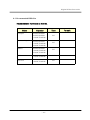
93
93
93
94
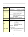
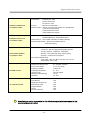
9. Standard Specification ---------------------------------------------------- 95
10. Lay Out --------------------------------------------------------------- 97
-- 7 --
Digital Video Recorder
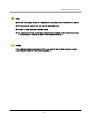
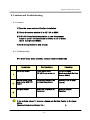
1. Safety Information
!
You should pay attention to these following information before installing DVR.
WARNING
◈ Do not expose the product directly to the sun or a heating apparatus.
( It is in danger of fire.)
◈ Do not leave vessels with water such as a vase, a flowerpot, cup, cosmetics.
( It may cause fire or electric shock and possible to be injured because of falling.)
◈ Do not put or fall metallic material (coin, hair pin, metal) or the inflammables
(paper, match) into a vent.( It may cause fire or electric shock.)
◈ Do not leave heavy stuffs on the product. (It may cause an injury as fall.)
◈ Do not expose the battery to children. If a child swallow the battery, consult with a doctor.
◈ Fix the power plug well in order to not vibrate. (Instable connection is caused a fire.)
◈ Take out the power plug under thunder or lightening. (It may cause a fire.)
◈ If the product is dirty,
* Polish the product with dry towel.
* Do not use chemicals or detergent. ( It may cause the cover is changed in quality
or paint could be removed .)
◈ Do not use the power plug with other power plug. ( It may cause a fire or heat.)
◈ Discontinue using if there is strange smell or smoke.
After turn off the power, contact to service center.
If you use as it is, it may cause a fire or electric shock.)
◈ Do not touch the power plug with wet hands.( Electric shock is possible )
◈ Do not pull the power cord. (If the part of power cord is damaged,
a fire or electric shock is possible.)
◈ Do not twist the power cord. It may cause a fire or electric shock.
-- 8 --
Digital Video Recorder
2. Part Names and Features
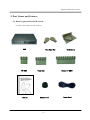
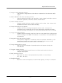
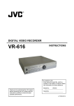
2.1 Basic Organization of DVR System
Contents and shape can be different.
DVR
RS-485
Manual
Hard Rack Key
Alarm Out
Rubber Foot
-- 9 --
Rack Mount
Sensor In (2EA)
Power Cord
Digital Video Recorder
2.2 Features
1) High quality digital recording
–
Output and playback High-Resolution digital recording by using Wavelet
compression and a restoration circuit.
2) Simple user environment
–
Simple operation by embedded hardware and jog /shuttle.
3) High reliability
–
Highly reliable due to a combination of hardware quality and LINUX
based operating system. Auto-diagnostic function provides quick
warning and troubleshooting advice for timely repairs in the event of a
system failure.
4) Simple setting and system maintenance
–
Enables simple installation and operation with basic setting
and camera inputs.
5) Diverse total security function
Enables security system by using sensor input, a contact point
control, and camera control.
6) Remote data back up
It is possible to back up and playback by using client program
via network.
7) Backup (IEEE1394 HDD, IEEE 1394 CDRW)
Massive amount of image backup is possible by using external
IEEE1394 and CDRW. Specially it is possible to extend HDD up to
20pcs and also possible to back up specific image by using
USB FDD, USB ZIP Driver via USB port.
8) Diverse monitoring function
Diverse monitoring is possible such as FULL/PIP/4/6/8/9/13/16
/user/ZOOM screen.
Specially you can watch monitoring screen while it is being recording.
9) Remote security function
–
Cameras can be remotely controlled and images can be viewed from
anywhere through a web browser over a private line or via the Internet
without any special software. System is compatible with PC or Mac with
any type of operating systems.
!
If the system is being backed up by HDD, you will not be able to use
playback (P/B) remote security function.( Live monitoring is possible
through a web browser )
-- 10 --
Digital Video Recorder
10) Audio recording playback function
–
Can record for long periods of time due to compression of the channel audio
signal.
11) Motion detection and event recording function
–
Detects optional field, label, and sensitivity of each channel, and able to record
automatic register by connection with an outside sensor.
12) Various search functions
–
Records quickly via diverse search conditions such as date, time, camera, and
ALARM, and search function while recording.
13) Diverse recording set-up options
–
Supports efficient recording management options such as screen size,
recording screen, frames per second, and compression rate while recording.
Efficient recording is possible as set up recording speed while event recording.
14) Diverse recording functions
–
Supports diverse recording criteria such as on-screen date/time, residuum mark
while recording, and ALARM LOG indicator. It is possible to record ALARMs and
programming.
15) Automatic check and recovery function
–
The system is designed for continuous, fault-free operation with built-in, selfmonitoring functions that monitor each component of the system and will
automatically restart if a system failure is encountered.
16) Diverse external device control
–
Able to control a multitude of external devices and cameras through the
RS-485 port.
17) Program upgrade function
It can be upgraded through internet or USB port when adds functions or
changes the program.
18) Multi password function
Each user can make ID and password and possible to control Setup,
PTZ, REC, PB menu.
19) Email Notification
Whenever events are happened, it sends email regularly as setup at Conditions.
-- 11 --
Digital Video Recorder
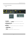
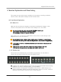
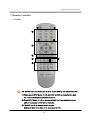
2.3 Part Name and Description
• Front
①
⑭
⑫
②
⑬
⑨
⑨
⑧
⑩
④
⑤
⑪
③ ⑥
⑦
1) Power Switch
: Power ON/OFF switch. IMPORTANT! Check the power source (AC115/230V)
before use!
2) INPUT Button (CH1 – CH16)
: These buttons are used to select the screen monitors and to change the channel
settings at the menu.
3) AUTO Button
: The input channel is automatically switched in proportion to the speed setting
at the menu.
ALARM RESET Button
: This button is to stop the alarm.
◀ Button
: This is for selecting Motion Grid or moving cursor to the left.
-- 12 --
Digital Video Recorder
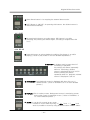
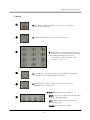
4) PANORAMA Button
: This button is for replay P/B screen with field unit.
▲ Button
: This is for selecting Motion Grid, changing character or moving cursor to up.
5) ZOOM Button
: This is used to zoom a freeze-frame in playback mode. Selected screen is X2,X3,X4.
ENTER Button
: This is for selecting set up Menu.
6) TRIPLEX Button
: This button is for replay PB screen to TRIPLEX mode.
▼ Button
: This is for selecting Motion Grid, changing character or moving cursor to down.
7) Freeze Button
: This button is for seeing monitoring and PB screen as pause screen.
Freeze image backup button
: It is for backup freeze image at external FDD.
▶ Button
: This is for selecting Motion Grid or moving cursor to the right.
8) Display Button
: This button is for viewing the various division modes of the monitor screen and
PB screen.
9) USER Button
: This is for user’s screen mode.
10) SET UP Button
: This button is for selecting or canceling the monitor setup menu mode.
11) REC, STOP, Reverse Playback (EXIT), PLAY Button (ENTER)
REC : This is for recording.
STOP : This is for stop PB.
Reverse Playback (EXIT) : This is for reverse PB. It is also for finishing menu setup,
moving to previous menu or erase wrong character.
PLAY Button (ENTER) : This is for playback and set up menu.
12) Jog Shuttle (REV, CUE, Up, Down)
: It is possible to ‘quick search’ during playback and also used to change the modes of
the menu.
Shuttle : This is for quick search when PB and it is used for change MENU.
JOG : This is for slow search when PB and it is used for moving MENU’ s cursor.
13) Backup HDD (Removable HDD or CD-RW)
: This is removable HDD or CD-RW and it is used for Backup or Main.
14) USB Port
: This is for connecting with external FDD or HDD to backup.
!
When connecting with external USB, please turn off the power.
!
If use IEEE1394 Port and USB Port together, connect IEEE 1394 port first then
turn on the DVR then connect USB port.
-- 13 --
Digital Video Recorder
• Rear
①
⑧ ⑨
④
②
③
⑥
⑤
⑦
⑫
⑩
⑬
⑭
⑪
1) RS-422 : For connecting with external Pan/Tilt camera.
2) LAN : Enables screen search and control via Internet.
3) RS-485 : For connecting with external Pan/Tilt camera.
4) SENSOR IN : For sensor input.
ALARM OUT : For control of other devices.
5) IEEE 1394 Port : For backup by using external HDD.
!
Please turn off the power when you connect external IEEE1394 with DVR.
!
If you connect external HDD with external CDRW, impossible to recognize.
Make sure external CDRW is connected with DVR first then connect with external HDD
to external CDRW. (daisy chain )
6) VGA OUTPUT : Possible to connect with computer monitor. (CRT type)
7) S-VIDEO OUTPUT : Outputs contents of monitor output as a S-VIDEO signal.
8) MONITOR OUTPUT (Composite) : Menu appears at the time of menu setting and
displays when screen search or recording.
9) SPOT OUTPUT (Composite) : Outputs video which is set-up from the menu.
10) AUDIO : I/O for audio playback.
11) VIDEO INPUT BNC & LOOP OUT (CH1 ∼ CH16)
: Inputs asynchronous video signal 1.0Vp-p.( 75 ohm )
: Loop out is changed to HI-Z automatically.
12) POWER Switch
: This is the main power switch.
13) AC SELECT : Select AC115V or 230V.
14) AC INLET : Input power voltage. Before using this switch, be sure the correct
power source is selected (AC115V/230V) by checking the AC SELECT switch!
-- 14 --
Digital Video Recorder
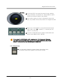
2.4 Power and Battery Setup
1) Power set up : Possible to select power (AC 115V/AC 230V) by AC Selector.
● Connect with AC110V if AC selector
is as left picture.
● Connect with AC220V if AC selector
is as left picture.
● Move select switch from the right to the left for selecting power.
!
See service instruction before connecting to the supply.
2) How to change battery
①
● For putting the battery in, please push the battery until you hear the locked sound.
For changing the battery, push ① as shown above picture.
(Please use 3V lithium battery.)
!
CAUTION
Risk of explosion if battery is replaced by an incorrect type. Dispose used
batteries according to the instructions.
3) How to change Fuse
● Please take off the power cord from the DVR when changing Fuse.
Please use a rated fuse F1 : T6.3AH 250V
-- 15 --
Digital Video Recorder
3. Explanation and Application
3.1 Basic Schematic of the DVR System
: This system can record up to 16 asynchronous video signals.
Ability to check multiple screens during playback by using monitors & VGA units. It supports screen
search, monitor, and remote control through the Internet.
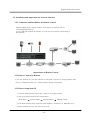
3.1.1 Basic Schematic
Video signal of the input channel is 1.0 Vp-p on a 75Ω load. Loop–Out is changed to Hi-Z
Automatically.
-- 16 --
Digital Video Recorder
3.1.2 Explanation of Schematic
● Able to input up to 16 video signals asynchronously.
Possible to connect with the other devices via Loop-out.
● Monitor output have 2 ports and spot output has 1 port.
● AUDIO
: Able to record sound signals (MIC or LINE) of a channel.
● RS-485
: Camera Control. (Pan,Tilt, Zoom, Focus)
● LAN
: It is used for internet connection for remote control and image
search of the product from a remote location.
Comprehensive control of the system is possible from a remote
location due to network setup.
● SENSOR IN
: This is the sensor input for external input.
Enables diverse event setups by sensor input.
● ALARM OUT
: This is the sensor output for signal transmission to other
devices.
● Supports video signal such as VGA, S-VGA for the product operation check.
● Able to connect with USB FDD or USB ZIP Driver.
● Able to connect with external IEEE 1394 HDD.
!
Please turn off the power when you connect external IEEE1394 or USB with
DVR for the purpose of avoiding damage. After power off, connect IEEE1394
or USB device and then turn on the power.
!
If you reset DVR, you have to power off the IEEE 1394 or USB device.
-- 17 --
Digital Video Recorder
3.2 Basic Connection
RS-485 Connector
USB Connector
IEEE 1394 Connector
LAN Connector
VIDEO INPUT Connector
SENSOR IN, ALARM OUT
Connector
VGA OUT Connector
S-VIDEO Connector
MONITOR OUTPUT
Connector
SPOT OUTPUT Connector
AUDIO INPUT
Connector
AUDIO OUTPUT
Connector
-- 18 --
Digital Video Recorder
3.3 Pan/Tilt Camera Connection and Control
It is possible to control the Pan/Tilt camera without special devices.
The Pan/Tilt camera supports RS-485 and is given an ID for parallel connection.
Easy to install from the graphic screen and possible to control by using the Jog Shuttle.
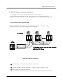
3.3.1 Pan/Tilt Camera Organization
Most of Pan/Tilt camera connections are linked with a power connection, control
terminal connection, and video signal output connection.
PTZ Camera
D
+
D
-
G
N
D
① ② ③
D
+
D
-
G
N
D
① ② ③
D
+
D
-
G
N
D
① ② ③
DVR
RS-485
D+
①
D-
②
If PTZ camera installs in place with noise, please use
Twist Pair Shield line.
GND terminal is common.
GND ③
Pan/Tilt Camera Connection
● Camera power connection : Motion power connection.
● Control terminal connection (RS-485) : Connects DA(D+), DB(D-), GND.
● Video signal connection(Composite)
: Checks video mode (NTSC/PAL) and inputs video signals at each input terminal.
-- 19 --
Digital Video Recorder
3.3.2 How to Setup
Pan/Tilt Camera Installation
DVR Installation
1. Installation
To install Pan/Tilt camera, select model name on Camera Setup of the
menu
2. ID Setting
Install ID value independently, 1~255
!
Sets camera ID to camera setup
and tests motion
You must to use the same product !
3.3.3 Control ( RS-485 )
General Pan/Tilt camera controls Pan/Tilt, Zoom, Focus, Iris by using 6byte command
format as per the following.
[ Baud rate : 9600 // Start bit : 1 // Data bit : 8 // Parity : None // Stop bit : 1 ]
Byte 1
Byte 2
Byte 3
Byte 4
Byte 5
Byte 6
Receiver ID
Transmitter
ID
OP Code
Data 0
Data 1
Check
Sum
[ Please special request if the product driver is not registered. ]
-- 20 --
Digital Video Recorder
3.4 External Product Connections and Applications
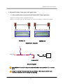
3.4.1 External Product Connection of SENSOR INPUT and Application
There are 16sensor jacks for external devices.
Able to set up REC ON/ OFF and Digital out motion according to SENSOR IN signals.
GND 1 2 3 4
5
6 7
8
GND 9 10 11 12 13 14 15 16
SENSOR IN 1
SENSOR IN 2
Connection Diagram
5V
SW
DC
SENSOR IN
GND
0
Common GND
Circuit Diagram
!
Each SENSOR IN should be connected with GND which is grounded by TTL or contact
point.
! Sensor In and Alarm Out ports must be used indoors. This product prohibit to use
outdoors. Because it can be damaged by lightning.
-- 21 --
Digital Video Recorder
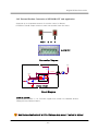
3.4.2 External Product Connection of SENSOR OUT and Application
Supports up to 4 separate sensors for motion control or alarms.
Possible to install output-events to each out terminal from the menu.
GND 1
2
3
4
ALARM OUT
Connection Diagram
VCC
+5V
1K
AR-OUT
+12V
-
LED
1
8
Q7
D22
RELAY SPDT
Internal Circuit
Circuit Diagram
OUTPUT EVENTS
Digital inputs to jacks 1~ 16, Full Disk, Signal Loss, Power Off, Network Access,
Floppy Access, Motion Detect.
!
Maximum output current is 0.1A. Damage may occur if output is higher!
-- 22 --
Digital Video Recorder
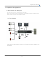
3.5 Installation and Application for Network Interface
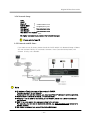
3.5.1 Connection and Installation for Remote Control
Supports Web server, remote control, and remote file transfer due to
10/100mega Ethernet I/F.
If you install the network as follows, you can use it soon after connecting to
the network.
Organization of Remote Control
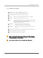
3.5.2 How to Connect by Domain
If you use dynamic IP, you can connect to DVR with a fixed IP by using dynamic DNS.
Refer to “Network=>More info” about present domain information.
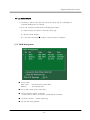
3.5.3 How to Setup Static IP
1) Connect Network line, which has a fixed IP, by using the hub.
2) Set up system network at the Setup Menu.
Main Menu
System Setup
Administration
Network Setup
3) Link web browser which supports JAVA Applets. ( Explorer 5.0, Netscape etc. )
4) After Network set-up, you can use at once.
-- 23 --
Digital Video Recorder
3.5.4 Network Setup
xDSL
DHCP
Static IP
: ____.____.____.____
Subnet Mask
: ____.____.____.____
Gateway
: ____.____.____.____
DNS Server1
: ____.____.____.____
DNS Server2
: ____.____.____.____
Web Sever Port Number :____
We highly recommend you consult the Network Manager.
!
Please refer to Page 72.
3.5.5 Network with IP Share
If you want to use IP share, please check the DHCP which is in Network Setup of Menu.
You can contact DVR by IP or domain. However, User 1(see the blow picture) can
contact IP only, not a domain.
!
Note
● IP Address : This is the name of the product in TCP/IP.
You can use any IP in one Network.
If you want to link with the Internet, you need an official IP address to avoid duplication.
● Subnet Mask : It is 32 Bit in length. ( = Address Mask )
● Gateway : This is used for connecting to the Network, which has a different structure
and Protocol.
● DNS : It is a link system for easy connection to the Internet.
For example, you can use an alphabetic address, e.g. www.company.com instead of a
number address.
● We highly recommend you consult the Network Manager.
-- 24 --
Digital Video Recorder
3.6 Application of Remote Control
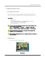
3.6.1 Using the remote control
This is for viewing live or searching playback screens from a remote location.
[ Quality of the live screen depends on the recording quality and Internet feed.]
How to Setup
1) Start browser.
( We highly recommend CPU : over 500MHz, RAM : over 64MB,
OS : over Win98, Browser : over Explorer 5.0 )
2) Enter IP number in the homepage address.
( Use Domain name )
!
If the icons are not displayed as change the screen, please check the menu
bar on the web site as followings.
Tools
Internet Options
General
Temporary Internet Files
Settings
Check for newer versions of stored pages
Automatically
!
If Record/Web Select is not selected on the menu, live monitoring is not
possible to see on the Web Browser.
!
When selecting divided screen, the screen display is possible to delay due to
network condition.
3.6.2 Web Browser
This is for wire internet by using computer.
Web Browser
-- 25 --
Digital Video Recorder
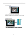
3.6.3 Live Screen Search
This is for searching 1, 4, or 16 channels simultaneously from a remote location.
It is possible to control the Pan/Tilt camera, which allows to set
up the position of the Pan/Tilt camera from a remote location.
► Pan/Tilt control : Possible to PAN, TILT and ZOOM by clicking the button on the web
screen.
3.6.4 Playback Screen Search
Year
Month
Day
Hour
Minute
Second
This is for searching playback screens. It is possible to check date and time.
-- 26 --
Digital Video Recorder
!
Note
● Remote monitoring is limited to 16 persons for assurance of the reliability of the system.
● Only one person is allowed to see the web playback screen.
● Possible to delay because of system status.
● The reliability of remote monitoring is subject to the reliability of the Internet connection.
( Try rebooting or resetting in case of Internet malfunctioning. )
!
Notice
If the product is being backed up by HDD in use, you will not be able to use the remote
control function.( but live monitoring is possible. )
-- 27 --
Digital Video Recorder
4. Function Explanation and Menu Setting
This system can set up the motion conditions of the camera, recording conditions,
sensors, audio, and system settings from the monitor menu.
4.1 Front Button Explanation
4.1.1 Before Use
Make sure all the devices are properly connected as described in Chapter 2, then
connect to the power source. This device uses voltage of AC 115V /230V.
!
Be sure to check the power source AC[115V/230V] before use!
This product tests itself after turn on the power.
(If problems are found, it reboots to 3 times.
After power is on, you will hear a slight buzzer sound, then it cycles through a self
diagnostic test for 20~50 seconds.
!
It automatically stores settings before shutting down. Therefore, it doesn’t need
to check for the setting every time providing there isn’t any specific changes made.
!
If the system is down, it restarts automatically and returns to the status just prior
to shutdown.
!
When you turn on/off the power, please use power switch on the front.
HDD can be damaged as you use main power switch on the rear.
4.1.2 Monitor Out
This product can simultaneously record while live monitoring. You can select a
screen form by using the DISPLAY button and INPUT button.
● It displays the selected channel on the monitor by pressing the INPUT button during
playback. It is used for selecting INPUT_CH at the MENU.
● Selected monitor configuration is displayed on the monitor “USER” button is for
screen configuration, which is set up from the menu. 1,4,9,16,7,13 and 7 screen is
displayed as pressing the DISPLAY button during playback.
-- 28 --
Digital Video Recorder
● Alarm Reset button is for stopping the external alarm motion.
● AUTO Button is ON/OFF. As pressing this buttons, the divided screen is
switched automatically.
4.1.3 REC
● By pressing this button, recording starts. REC button is on while
recording. As pressing this button again, recording is stopped and LED
is off.
4.1.4 PLAY
● Press this button to select playback condition. Play button is on while
playing. ( Refer to play mode for a more detailed explanation. )
● DISPLAY : It displays multi-screen when its’
monitoring or playback.
As pressing this button repeatedly
when its’ monitoring, divided
screen is displayed1/4/9/16/13/7/6
and as pressing this button
repeatedly when its’ playback, divided
screen is displayed 1/4/9/16.
● PANORAMA : One playback screen is displayed with time slice on 16
divided screen. ( Refer to FIGURE4.1.4 for a more detailed
picture. )
● TRIPLEX : This is overlay screen. Background screen is monitoring screen
and overlay screen is playback screen. ( Refer to FIGURE4.1.4
for a more detailed picture. )
● ZOOM : It can be X2 zoomed at any mode.
Possible to zoom status by using X (
) axis , Y (
) axis
and it is possible to move by using direction button in zoom status.
-- 29 --
Digital Video Recorder
SHUTTLE
● JOG & SHUTTLE can search by frame in play mode by
using JOG when it is paused ( ll ) and possible to quick
search by revolution speed of the shuttle.
JOG
● At the menu setting, the item is selected by using JOG
and it is possible to move the position or change the value.
● When it’s in PLAY MODE, it moves like the blow button
mark. (REC, stop ( ■ ) / pause( ll ) / reverse play (◄ )
/pause ( ll )/ play (►))
● It moves as indicated by the symbol located above the
button at the MENU. (EXIT, ENTER)
!
If you press the ENTER button after replay screen, it will be paused then you
can exact search by a field using Jog. You can search quickly by using shuttle
when its’ replay and you can search slowly by using Jog.
4.1.5 Menu Setup
● You can easily change the Camera Setup, Recording Setup,
and Audio Setup by the graphic user interface screen.
-- 30 --
Digital Video Recorder
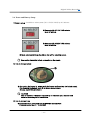
4.1.6 Explanation of Panorama and Triplex
● PANORAMA : One playback channel is replayed to 16 divided screen as
a time slice.
The channel which you want to replay will be displayed in a playback
mode. It switched 1,4,9,16 screen as pressing the DISPLAY Button.
PANORAMA Playback Screen of 16 Channel
● TRIPLEX : This is Overlay screen. You can monitor live screen and playback screen at the
same time. It is returned to playback screen as pressing the playback button
(ENTER button) after setup monitoring channel you want to see.
If you want to change playback screen, press the CHANNEL button.
TRIPLEX Playback Screen
-- 31 --
Digital Video Recorder
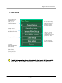
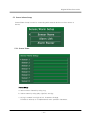
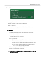
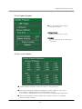
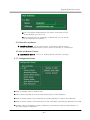
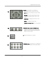
5. Main Menu
Control Camera,
Camera Setup,
Pan / Tilt of
Pan/Tilt Camera.
Set up Recording
Channel Selection,
Common Option,
Schedule Events.
Set up Sensor
Name, Alarm Link
and Alarm Buzzer.
Select 8 screen
group which is
displayed when you
press the “User”
button.
Set up Audio Setup.
Set up Language
and Transparency.
Log View
HDD Management
HDD Backup
Auto Select
Video Output
Administration
Factory Default
About System.
!
Possible to change setting status to factory default values by using the Factory Default
System Setup. (However, Clock, Network Setup, and Password are not changed.)
-- 32 --
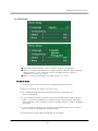
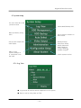
Digital Video Recorder
5.1 Camera Setup
It is possible to set up image which will connect at input port and able to set up Pan/Tilt
camera which will connect with RS-485.
5.1.1 Camera Control
Make sure all of the Pan/Tilt cameras are the same manufacturer.
Use the cameras which are supported by the same protocol.
1) RS-485 enables long distance transfer.
2) Almost all control of the Pan/Tilt cameras is done via the RS-485.
3) Possible to connect in parallel.
5.1.1.1 Pan/Tilt Camera
Camera ID Setup
Examples of Camera Rotation
Pan
Camera
Pan/Tilt Camera
-- 33 --
Tilt
Digital Video Recorder
5.1.1.2 How to Use
1) Checks camera ID setup value from the camera setup menu.
2) Selects Pan/Tilt Control from the menu.
3) Selects motion by Jog.
4) Moves shuttle left to right.
Checks whether camera ID and Pan/Tilt camera ID are the same installation if
the Pan/Tilt camera does not activate.
Also, checks whether the control line of the Pan/Tilt camera is in the correct
location.
5) Press the EXIT button to return to the normal screen.
-- 34 --
Digital Video Recorder
5.1.2 Camera Setup
Setup channel
● Installs Name, Control ID (Pan/Tilt Camera), Model and Color (Brightness,
Contrast, Saturation, Hue) of each channel.
5.1.2.1 How to Setup
1) Checks the channel number as indicated at the bottom of the tab, and then
checks whether the background is the correct screen.
(The channel number can be changed by pressing the INPUT Number button.)
2) Selects contents which you want to change by jog.
3) Possible to change
ENTER button
EXIT button
◀ button
▶ button
Jog
setup status by using the buttons as follows.
: Change and complete selected contents.
: Make cancellation.
: Move to left at the Nickname.
: Move to right at the Nickname.
: Can change character and number by jog rotation.
4) To return to the preset menu, press the EXIT button.
5) If a Pan/Tilt camera is connected, test after setting-up the camera ID.
-- 35 --
Digital Video Recorder
5.1.2.2 Camera Name
● Name : Possible to create an alphanumeric nickname of up to 16 characters
(including symbols) as shown below.
You can see the next character repeatedly by Jogging.
Character Mark
Blank ! “ # $ % & ’ ( ) ” + , - . / 0 1 2 3 4 5 6 7 8 9 : ; < = > ?
@ABCDEFGHIJKLMNOPQRSTUVWXYZ
[\]^_’abcdefghIjklmnopqrstuvwxyz{|}~
How to Use
1) Selects Name by Jog.
2) Possible to write and amend if you press the ENTER button.
3) Writes and amends by using the RIGHT/LEFT button and Jog.
4) Complete by clicking the ENTER button.
5.1.2.3 Pan/Tilt Camera Setup
● Camera Setting : Control ID, Reverse Pan, Reverse Tilt, Control Test, Model
1) Control ID : For controlling the Pan/Tilt camera.
Setting ID is for separating the Pan/Tilt camera, which is connected in parallel.
Control ID uses 1~255 number.
( Be sure to check the specifications of the Pan/Tilt cameras. )
2) Reverse Pan, Reverse Tilt : It reverses a Pan/Tilt Camera direction.
Usually, the Pan/Tilt direction can be changed depending on the location
and mounting of the Pan/Tilt camera.
3) Control Test : Possible to test whether Pan/Tilt Camera setup is correct or not.
Useful when checking after setup finishes.
All settings are automatically stored, so there is no need to change the setup as
long as there is no special reason.
4) Model : Set up Pan/Tilt Camera to control for each channel.
-- 36 --
Digital Video Recorder
5.1.2.4 Adjustment
● Possible to install each input video color ( Brightness, Contrast, Saturation ) value
as a number 0~100 and Hue can be installed as a number -50~50.
Please, install a proper value for a background checking screen.
● How to Setup
1) Move to the desired position by using Jog.
2) If you press the ENTER button, the next image is displayed with video input.
3) Jog from left to right for changing the number. This is for color control.
4) If you select either the PLAY or EXIT button, setup is finished. After
finishing setup, the previous screen is displayed.
Brightness : Controls brightness.
Contrast
: Controls contrast.
Saturation : Controls saturation.
Hue
: Controls hue.
-- 37 --
Digital Video Recorder
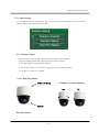
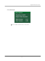
5.1.3 Pan/Tilt Model Select
After
register
drive
No Registered Model
Selects one of camera which is
registered driver
!
If Pan/Tilt model is not registered, ask the dealer from whom you purchased the
unit.
!
Possible to register Pan/Tilt model through the external FDD or LAN if Pan/Tilt is
not registered.
● How to Setup
1) Connect the Pan/Tilt device to the RS-485 port.
2) Select the same drive, which is selected from the “Pan/Tilt Model Select”
menu.
(If there is unusual motion and there is no drive, ask the dealer from whom
you purchased the system.)
3) Select port to control.
4) Set-up the Camera ID at “Camera Setup”.
5) Test it by using Camera Control.
● Sets up baud rate for each cameras
(Factory default is 9600 bps)
-- 38 --
● Select port according to Pan/Tilt Model.
PORT A : RS-422
PORT B : RS-485
Digital Video Recorder
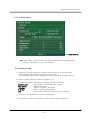
5.2 Recording Setup
Able to setup content related with Recording Setup.
5.2.1 Schedule
● Able to schedule recording by weekday, time and channel.
● Able to schedule recording of specific date.
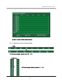
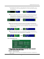
● Able to alternately see menu to view 24 hours and 16 channel schedule status
on a screen and menu to view detailed schedule status if pressing the ‘USER’
button.
● Recording field rate is not displayed to view 24 hours and 16 –channel
schedule status on a screen.
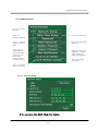
● Menu to view 24 hours and 16ch schedule status on a screen.
-- 39 --
Digital Video Recorder
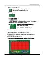
● Menu to view detailed schedule status.
5.2.1.1 Explanation of Recording Schedule
1) Time
or
● The above number indicate time. (00 ~ 21)
2) Channel
or
● The left number indicate channel. (1 ~ 16)
-- 40 --
Digital Video Recorder
3) Quality Level, Alarm Recording
● QL indicates quality level as recording.
● AR indicates whether Audio Recording or not.
4) Recording Events
● A : Always Recording.
● S : Sensor Recording.
● M : Motion Recording.
● 360/720 : Recording Resolution.
● fps/fps : The first ‘fps’ means field rate of Always Recording, the second ‘fps’
means field rate of Alarm Recording/Motion Recording.
ex)
Always performs recording and 3fps recording in
the 360 horizontal pixel numbers.
Perform Sensor, Motion Recording and 3fps
recording in 720 horizontal pixel numbers.
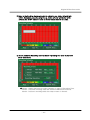
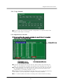
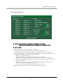
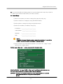
5.2.1.2 How to Setup
- Menu to view 24hours and 16ch schedule status on a screen.
● Recording Schedule setup is don in block unit and 1 block means a hour at a
specific channel.
● How to Setup Recording Schedule Block
1) No.1 channel block is designed at 00 hour if pressing the ‘ENTER’ button.
-- 41 --
Digital Video Recorder
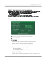
2) Move to the block to change schedule by using the up, down, left and right
button. Designate group by using the up, down, left and right button while
pressing the ‘STOP’ button in order to select various buttons at a time.
3) Able to setup the Recording Event as below if pressing the ‘Enter’ button with
group designated.
● Always : Always performs recording operation in case of Recording Time.
Sensor : Performs recording when the selected SENSOR IN comes in.
Motion : Performs recording within the setup screen of channel.
-- 42 --
Digital Video Recorder
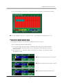
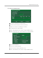
4) You can be aware of that color of the block whose schedule is changed after setup.
● QL, AR, weekday, Copy To…, Specific Days…are explained in detail below 5.2.1.4
● Menu to view detailed schedule status
- Recording Schedule is set up in block. Minimum block is an hour.
- How to Setup Recording Schedule Block
1) As using left/right direction button, designates time block at the same channel.
As using up/down direction button or jog, designates channel block at the time
zone of 0 hour.
2) As pressing one of ‘DISPLAY’ button at the block to change, the following picture
will display in order.
● Appears yellow bar at the left of block.
● Appears yellow bar at the right of block.
● Disappears yellow bar at the block.
-- 43 --
Digital Video Recorder
3) As pressing the left button in case yellow bar is at the left of the block : The
block extends for at hour and extended time is set up as Recording Schedule
of present block.
● When the yellow bar is located in the left side of the block and you press the
right arrow button, then the source configuration in the block will be deleted
(reduced) and the configuration in the deleted block will follow the
configuration in the left block. (But, if the current block is located in the most
left side, then the configuration of deleted block will follow the default setting.)
● When the yellow bar is located in the right side of a specific block and you
press the left arrow button, then the source configuration of the block in the
right side of the current block will copied (expanded) (But, if the current block is
located in the most right side, then the configuration of deleted block will follow
the default setting.)
● When the yellow bar is located in the right side of a specific block and you
press the right arrow button, then the source configuration of the block in the
current block will be copied (expanded) to the right block.
5.2.1.3 Recording Events
● When you select a specific block and press the ‘Enter’ button, then you will
be able to set the configuration as above.
● Always : Always Recording
Sensor : Sensor Recording
Motion : Motion Recording (The area designated will follow the configuration in
Menu setup.)
-- 44 --
Digital Video Recorder
5.2.1.4 Quality
● When you place the bar in QL and press the ‘Enter’ button, then you will be
able to configure the Recording Quality.
● Quality setup range : 1 ~ 7
● Quality could be set up according to time table such as Schedule.
5.2.1.5 Audio Recording
● When you place the bar in AR and press the ‘Enter’ button, then you will be
able to select Audio Recording On and Audio Recording off as below.
or
● Audio Recording On
or
● Audio Recording Off
● Audio Recording could be set up differently according to time table by using
Display button such as schedule.
5.2.1.6 Setup Days of the Week
● Possible to select a
day of the week for
changing REC schedule
by using Enter and Jog.
● You can select a day to configure the recording schedule using Enter
button and Jog dial.
-- 45 --
Digital Video Recorder
5.2.1.7 Copy Schedule
● You can copy the recording schedule configuration of a specific day of the
week to other days of the week.
5.2.1.8 Specific Days Schedule
● You can configure the recording schedule of a specific day of by pressing
‘Enter’ button in the ‘Specific Days…’
Add new Schedule
Decide whether record
or not as setup schedule.
Delete the selected Schedule.
● Using the left/right arrow buttons and the ‘Enter’ button and selecting the
‘Add’, you can add and configure new Specific Day Schedule up to max 16.
● Using the up/down arrow buttons and the ‘Enter’ and jog dial and selecting
the ‘Disable/Enable’ you can decide if you will record it according to the
configuration of recording schedule, or not.
● Using the up/down arrow buttons and the ‘Enter’ and Jog dial and selecting
the ‘Delete’, you can delete the configured recording schedule.
● QA : Q means quality level when recording and A means Audio Recording.
-- 46 --
Digital Video Recorder
● You can set the start and the end time of the schedule recording for the specific day.
5.2.2 Recording Events
5.2.2.1 Common Option
● Setup record time before and after occurrence of event when Sensor / Motion Event
occurs.
-- 47 --
Digital Video Recorder
● How to Setup
1) Move to the place you want to change setup by using Jog.
2) Select the recording quality from the menu by using the ENTER button
and LIST BOX as displayed below.
Quality : 7 levels
Prev Time : Long Time, Middle Time, Short Time
Post Time ; 1~99 sec
It is recording the highest Frame/Sec automatically.
Before Time is a little different according to System mode.
Usually, Long/Middle/Short Time is divided 1~5sec by 3.
3) Setup menu is automatically applied to move to the previous menu.
● Recording is stopped for a sec after Record Select setting.
5.2.2.2 Sensor Input
● Sensor : Selects Sensor Input (1-16).
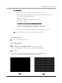
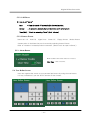
5.2.2.3 Motion Detect
● Motion Detect : Set up Motion Detect.
Full : Recording starts when motion is detected in full screen.
Area : Recording starts when motion is detected in selected area.
● Field Setup
Field can set up by Jog and direction buttons. The following image is a
preset screen of the field setup when selecting full and area.
Full
Area
-- 48 --
Digital Video Recorder
● How to Setup
ⓐ Jog direction of field setup.
X-axis
Direction Button
Jog Direction
Y-axis
Direction Button
ⓑ The user field setup is moved to the place by jogging. The first
location and the last location can be selected by clicking enter.
ⓒ Area field setup is moved to the place by jogging and can check the
field by using ENTER.
ⓓ After setup is finished, move to the higher level menu by clicking EXIT.
● Possible to set up Sensitivity at the Motion Detect (1~ 30)
Motion is detected in proportion to sensitivity value. Factory default value is the
standard motion detection sensitivity.
● The recording stops for about 1 second after setup.
5.2.3 Manual Recording
Manual Recording is for setup recording condition of each channel as pressing
REC button when it is not recorded according to schedule.
● Press the ENTER key after
select one by Jog then selected
channel will be the blue bar like
right picture.
● Possible to control recording for each channel as pressing REC buttons.
-- 49 --
Digital Video Recorder
● As pressing Enter button after moving cursor to channel by using Jog,
channel for setup will be changed blue bar as blow.
In case Schedule Recording box
is checked, Manual Recording
Is not working.
!
In case Schedule Recording box is checked, recording is proceed according to
schedule regardless of Manual Recording. For using Manual Recording, do not
check Schedule Recording box.
!
Recording is not started when Record check box is not checked. Must check
Record check box for Manual Recording.
· A : Always Recording
· S : Sensor Recording
· M : Motion Recording
· fps/fps : The former ‘fps’ is field rate of Always Recording, the latter ‘fps’ is
field rate of Alarm Recording/Motion Recording.
● As pressing ‘Enter Key’ at this mode, the blow menu appears for setup recording option.
5.2.3.1 Recording Events
● The way of setup is the same with Schedule Recording.
● Press the EXIT button after finish setup then possible to return Schedule Recording.
-- 50 --
Digital Video Recorder
5.2.3.2 Quality
● As same as Schedule Recording, when press the ENTER button at QL, possible to
set up Recording Quality.
● Setup range : 1 ~ 7.
● After setup, press the EXIT button to return previous menu.
!
After setup conditions, recording is stopped for about 1 second to reset program.
-- 51 --
Digital Video Recorder
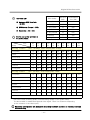
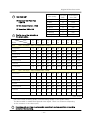
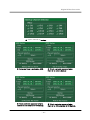
After Recording Schedule setup, it is not recorded for a second for reset up program.
As each input line is selected, the maximum recording Frame/Sec is changed as in the
below table. ( Only for NTSC )
1CH → 30F/S
2CH → 30F/S
3CH → 30F/S
4CH → 30F/S
5CH → 15F/S
6CH → 15F/S
7CH → 15F/S
8CH → 15F/S
9CH → 10F/S
10CH → 10F/S
11CH → 10F/S
12CH → 10F/S
13CH → 7F/S
14CH → 7F/S
15CH → 7F/S
16CH → 7F/S
[Table 1.1] NTSC, Horizontal Pixel : 360, unit :Field/Sec
As each input line is selected, the maximum recording Frame/Sec is changed as in the
below table. ( Only for PAL )
1CH → 25F/S
2CH → 25F/S
3CH → 25F/S
4CH → 25F/S
5CH → 12F/S
6CH → 12F/S
7CH → 12F/S
8CH → 12F/S
9CH → 8F/S
10CH → 8F/S
11CH → 8F/S
12CH → 8F/S
13CH → 6F/S
14CH → 6F/S
15CH → 6F/S
16CH → 6F/S
[Table 1.2] PAL, Horizontal Pixel : 360, unit :Field/Sec
As each input line is selected, the maximum recording Frame/Sec is changed as in the
below table. ( Only for NTSC )
1CH → 30F/S
2CH → 30F/S
3CH → 15F/S
4CH → 15F/S
5CH → 10F/S
6CH → 10F/S
7CH → 7F/S
8CH → 7F/S
9CH → 6F/S
10CH → 6F/S
11CH → 5F/S
12CH → 5F/S
13CH → 4F/S
14CH → 4F/S
15CH → 3F/S
16CH → 3F/S
[Table 1.3] NTSC, Horizontal Pixel : 720, unit :Field/Sec
As each input line is selected, the maximum recording Frame/Sec is changed as in the
below table. ( Only for PAL )
1CH → 25F/S
2CH → 25F/S
3CH → 12F/S
4CH → 12F/S
5CH → 8F/S
6CH → 8F/S
7CH → 6F/S
8CH → 6F/S
9CH → 5F/S
10CH → 5F/S
11CH → 4F/S
12CH → 4F/S
13CH → 3F/S
14CH → 3F/S
15CH → 3F/S
16CH → 3F/S
[Table 1.4] PAL, Horizontal Pixel : 720, unit :Field/Sec
-- 52 --
Digital Video Recorder
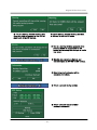
REC TIME LIST
!
!
REC Quality
File Size
(KB)
Consumption
/sec (KB)
● Maximum REC Field Rate
: 60 F/S
7. Very Best
18
1080
6. Best(6)
17
1020
● REC Screen Channel : 16Ch
5. Very Good
15
900
● Resolution : 720 * 240
4. Good
13
780
3. Very Normal
10
600
2. Normal
7
420
1. Long Time
5
300
The file size of the right table is
for general office.
Term
Quality
Recording Condition
3F/
1S
2F/
1S
1F/
1S
1F/
2S
1F/
3S
1F/
4S
1F/
5S
1F/
6S
1F/
8S
1F/
16S
HDD : 120 GByte, Audio Sampling Rate : 8 KByte
7. Very Best
33
49
98
195
293
391
488
586
781
1563
6. Best
38
57
114
228
342
456
570
684
911
1823
5. Very Good
43
65
130
260
391
521
651
781
1042
2083
4. Good
49
73
146
293
439
586
732
879
1172
2344
3. Very Normal
65
98
195
391
586
781
977
1172
1563
3125
2. Normal
92
138
277
553
830
1107
1383
1660
2214
4427
1. Long Time
130
195
391
781
1172
1563
1953
2344
3125
6250
Recording Condition
HDD : 120 GByte, Audio Sampling Rate : NONE
7. Very Best
38
57
114
228
342
456
570
684
911
1823
6. Best
38
57
114
228
342
456
570
684
911
1823
5. Very Good
43
65
130
260
391
521
651
781
1042
2083
4. Good
49
73
146
293
439
586
732
879
1172
2344
3. Very Normal
65
98
195
391
586
781
977
1172
1563
3125
2. Normal
98
146
293
586
879
1172
1465
1758
2344
4688
1. Long Time
136
203
407
814
1221
1628
2035
2441
3255
6510
(Unit : Hour)
(You can control recording quality from Recording Quality of the System Setup.
The above table is standardized general video signal. There is a difference depending
on the contents of the video input.)
!
Recording data and time are changeable according to system operation or recording contents
while recording.
-- 53 --
Digital Video Recorder
● Maximum REC Field Rate
: 120 F/S
● REC Screen Channel : 16Ch
● Resolution : 360 * 240
!
The file size of the right table is
for general office.
Term
Quality
Term
File/Size
(KB)
Consumption
/sec (KB)
7. Very Best
11
1320
6. Best
10
1200
5. Very Good
9
1080
4. Good
8
960
3. Very Normal
6
720
2. Normal
5
600
1. Long Time
3
360
REC Quality
REC TIME LIST
!
7F/
3F/
2F/
1F/
1F/
1F/
1F/
1F/
1F/
1F/
1S
1S
1S
1S
2S
3S
4S
5S
8S
16S
HDD : 120 Gbyte, Audio Sampling Rate : 8 Kbyte
7. Very Best
23
54
81
163
326
488
651
814
1302
2604
6. Best
28
65
98
195
391
586
781
977
1563
3125
5. Very Good
30
71
106
212
423
635
846
1058
1693
3385
4. Good
35
81
122
244
488
732
977
1221
1953
3906
3. Very Normal
47
109
163
326
651
977
1302
1628
2604
5208
2. Normal
56
130
195
391
781
1172
1563
1953
3125
6250
1. Long Time
93
217
326
651
1302
1953
2604
3255
5208
10417
Term
HDD : 120 Gbyte, Audio Sampling Rate : NONE
7. Very Best
26
60
90
179
358
537
716
895
1432
2865
6. Best
28
65
98
195
391
586
781
977
1563
3125
5. Very Good
33
76
114
228
456
684
911
1139
1823
3646
4. Good
37
87
130
260
521
781
1042
1302
2083
4167
3. Very Normal
49
114
171
342
684
1025
1367
1709
2734
5469
2. Normal
58
136
203
407
814
1221
1628
2035
3255
6510
1. Long Time
98
228
342
684
1367
2051
2734
3418
5469
10938
(Unit : Hour)
(You can control recording quality from Recording Quality of the System Setup.
The above table is standardized general video signal. There is a difference depending
on the contents of the video input.)
!
Recording data and time are changeable according to system operation or recording
contents while recording.
-- 54 --
Digital Video Recorder
5.3 Sensor/Alarm Setup
Sensor/Alarm Setup is used for connecting with external devices such as sensor or
buzzer.
5.3.1. Sensor Name
How to Setup
a. Select sensor channel by using Jog.
b. Selects name by using play, right/left, and jog.
c. As jog is rotated from right to left, characters change.
Possible to write up to 15 alphanumeric and symbolic characters.
-- 55 --
Digital Video Recorder
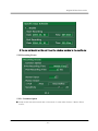
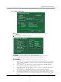
5.3.2 Alarm Link Setup
● Events : Select condition of Alarm Out. Duplication is possible.
This product has Sensor Input of 16EA and Alarm Output of 4EA.
● How to Setup
a. Select Alarm Link CH by using INPUT CH button.
b. Select Alarm Output Number by using Channel Button(1ch~4ch).
( The above picture is set up Alarm Output 1. Alarm Output has 4 outputs.)
c. Check the conditions of Sensor, Events, Alarm off by using Jog and Enter button.
▪ Check the events you want to check at “Events”.
- Disk Full : When HDD is full.
- Admin.PW Changed : When Admin. Password is changed.
- Video Loss : No video signal ( Possible to select All or channel number.)
- Motion : When motion is detected. ( Possible to select All or channel number.)
▪ Check the “Alarm Off”
- Manual : Alarm is off as you press the ALARM RESET button at the front.
- N/O,N/C : Set up basic output of Output.
- Auto : Alarm is off automatically after setup time is over.
d. Move to previous menu after finish setup by using EXIT button.
-- 56 --
Digital Video Recorder
5.3.2.1 AR Reset
● How to off “Alarm”
Auto
: Alarm is turned off automatically after setting time.
Manual
: As press the Alarm button on the front, alarm is turned off.
Time (Min) : This is for selecting “Auto”. (Unit : Minute)
5.3.2.2 Sensor Events
Sensor In1~16
Disk Full
Signal Loss
Power Off
Floppy Access
Motion Detect
Contact point of the Alarm Out port is moved by selecting Sensor Events.
Refer to contents of external product connection. (Alarm Out is an open collector.)
5.3.3. Alarm Buzzer
Make enable buzzer when Alarm is occurred.
Clear Time : Time for buzzer.
5.4 User Define Screen
User can organize the screen to your personal preference by using the user button.
It is very convenient if you use AUTO function at User Screen.
-- 57 --
Digital Video Recorder
● How to Setup
1) Select one of 8 variations of multi-screen views by using Jog.
(NTSC : 8 Screen, PAL : 8 Screen)
2) As color is changed to blue, change the screen by using INPUT CH Button.
ⓐ Change by using the ENTER button.
ⓑ Change the screen, which color is blue, by selecting the INPUT Button.
ⓒ Move to another screen by using Jog.
ⓓ After finishing, select either ENTER or EXIT.
3) After setting end, finish the menu and then press the “USER” button of screen
button. User Screen will display as press the INPUT CH on USER SCREEN mode.
-- 58 --
Digital Video Recorder
5.5 Audio Setup
● Audio is capable of recording one channel.
● Sampling Rate is 8 KHz.
● Bypass is possible to Audio Out as recording Audio.
● Gain is from 0 to 5.
● Audio can be recorded, provided that Audio of Channel Selection at
Recording Setup is checked
● How to Setup
1) Selecting Audio Setup from the menu, displays the above picture.
2) Select “Bypass Audio”.
3) Select “Bypass Audio”.
You can hear sound from “Audio Out”.
4) For audio recording
① Select “Channel Selection” from the Recording Setup.
Check whether Audio is set-up or not.
② Select Channel of Related Video Channel from the Audio Setup.
③ Check whether Channel of Related Video Channel is set up or
not at Channel Selection of Recording Setup.
5) Finish by using either the ENTER or EXIT button.
6) Audio is recording as REC button is on.
!
This product is for video recording so quality of audio sound is lower than
general audio product.
-- 59 --
Digital Video Recorder
5.6 Menu Setup
● Can select Menu language such as English, Spanish, Portuguese.
● Status : It controls transparency of present status( channel name, recording
status indicator, clock, indicator of HDD recording amount ) which is
displayed on screen. (0 ~ 80%)
● Menu : It controls transparency of Menu screen. (0 ~ 80%)
● How to Setup
1) Selecting Menu Setup from the menu, displays the above picture.
2) Move to the place you want to set-up by Jog.
3) For changing language, press the ENTER button at Language and
select the language.
4) If you change the value by jog as pressing the ENTER button after moving to
Status, it controls transparency of present status( channel name, recording
status indicator, clock, indicator of HDD recording amount ) which is displayed
on screen.
5) If you change the value by jog as pressing the ENTER button after moving to
Menu, it controls transparency of Menu screen.
6) Finish setup by using either the ENTER or EXIT button.
-- 60 --
Digital Video Recorder
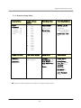
5.7 System Setup
You can check all of the
product motion.
Select Main/Backup HDD.
Back up data by using
HDD.
Set up motion contents of
Auto button.
Set up Spot Output and
VGA Output.
Network Setup,
Date/Time Setup,
Admin Password,
Web Password,
Covert Channel,
Update Program
Able to store
system settings at
or recall them from
the USB.
Check system version.
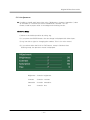
5.7.1 Log View
● Log records all motions which happened on the system.
● Easy to use by using Date or Filter.
-- 61 --
Digital Video Recorder
● How to Setup
1) Log shows all motions and setup contents while System is on.
2) You can check “Log” by the following :
① Set-up start date, which will be marked on the LOG, by Jog.
Select year/month/day by using the right/left button.
Change year/month/day number by using Jog.
② Select “Log Filter” for quick search.
③ Select “Display” button.
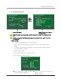
● Log Screen
Log screen contents are as follows:
Sensor In 1-16
Disk Full
Signal Loss
Power On/Off
Network Access
Menu Setup
Motion Detect
-- 62 --
Digital Video Recorder
● Log Screen Search
1) Possible to search from the Log Screen by using Jog. The sandglass is
indicator waiting time for search.
2) You can check the events by the following procedure:
① Select events you want to check by using Jog.
② Click the Enter button.
③ If you click the Stop( ■ ) button, screen search is stopped.
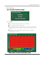
5.7.2 HDD Management
● Set up HDD
Main HDD : Can be used for basic REC.
Backup
: For backup HDD.
● Set up REC mode of the main HDD.
● Set up overwrite mode. Overwrite
: If HDD has no space to record, it automatically overwrite.
● Log clear function. : Delete stored log.
● Set up HDD using percent.
-- 63 --
Digital Video Recorder
● HDD Information
● This is for information of
Local HDD.
● Set up HDD.
Main
: Basic HDD for recording.
Backup : For backup HDD.
● Initialize : Initialize HDD.
● This is for information of external
IEEE 1394 HDD.
As clicking the Indicator on the
menu, you can know which HDD is.
!
Please turn off the power when you connect external IEEE1394 or USB with
DVR for the purpose of avoiding damage. After power off, connect IEEE1394
or USB device and then turn on the power.
!
If you reset DVR, you have to power off the IEEE 1394 or USB device.
!
When use external IEEE 1394 HDD drive, make sure it is connected to
external IEEE 1394 HDD drive at the HDD Management menu.
!
When use external IEEE 1394 CD-R/RW, connects with DVR first before
connecting with external HDD device.
-- 64 --
Digital Video Recorder
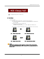
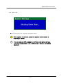
● It is displayed when HDD is almost full.
● How to Setup
1) Add new HDD.
① When adding a new HDD, you must turn the power off.
② If there is information of a new HDD, HDD Management is displayed at
the first stage.
③ Must need more than one Main HDD.
Backup HDD is only one.
Possible to install a maximum of 4 HDD. (Main 3ea, Backup 1ea)
④ It is better to clear the date when an HDD is registered for the first time.
MAIN
IDE1 : Master (Internal HDD)
IDE1 : Slave (Internal HDD)
BACKUP
IDE2 : Master (Internal HDD)
!
IDE2 : Slave (Removable HDD)
Notice
If you make a mistake during HDD installation or removal, HDD contents can be
erased. ( Ex. When changing Main HDD to Backup HDD or changing Backup HDD
to Main HDD.)
-- 65 --
Digital Video Recorder
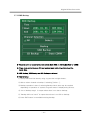
2) Overwrite Disk When Disk Full
Monitor screen displays a similar message as the following according
to overwrite on/off.
On
Main HDD is full, it starts to overwrite old DATA.
Off
When Main HDD is full (100%), recording is stopped.
3) Clear All Previous Log.
It is the place for initial Log content.
It is better to initiate Log, when HDD or DATA is changed.
-- 66 --
Digital Video Recorder
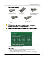
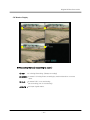
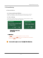
5.7.3 HDD Backup
● Records some of contents recorded on the Main HDD on the Backup HDD or CDRW.
● There must exist a Backup HDD and content must exist at hour/minute of the
setup date.
● HDD Backup, USB Backup and CD Backup are allowed.
● How to Setup
1) Set up Start and End date by using Jog and the left/right button.
2) Able to select channel to backup if selecting [Select…].
3) Backup operation is done if selecting Backup. Much time may be required
depending on operation of system. Progress status is displayed by percent.
4) “Out of backup range” is output where there is no date to backup.
5) “Backup HDD not found” is output where there is no HDD to backup.
6) Press EXIT button in cancellation during backup.
-- 67 --
Digital Video Recorder
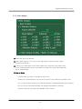
● Select channel to backup.
● It displays there is no backup HDD.
● This is a window appeared when
there is no data to backup
● This is a window appeared when a
recorder is not installed in CD backup.
● This is a window appeared when
there is no CD to backup in CD backup.
-- 68 --
Digital Video Recorder
● This is a warning window showing that
Recorder does not operate at the HDD of
main body during CD backup.
● This is warning window showing that data
at CD may be lost for CD erase.
● This is a warning window appeared when
pressing MENU for suspension for CD
backup and showing that damage to media
may occur.
● Checks data capacity to backup and
available space at CD-RW for CD backup.
● Determine whether backup will be
executed after check.
● This is a window during backup.
● This is a window appeared when
backup is completed.
-- 69 --
Digital Video Recorder
● How to connect removable HDD
Separate inside
rack from hard rack.
Open inside rack and
push top cover.
Fix the hard drive
to the inside rack
with 4 screws as
shown.
Connect data cable of
the inside rack with the
power line exactly.
Close the cover of
the inside rack.
!
Notice
If the product is being HDD backed-up, you will not be able to use the playback
(P/B) remote control function. ( Live monitoring is possible )
!
When add HDD or take HDD, please turn off the power. HDD is possible to damage
when its’ remove while power is on.
5.7.4 Auto Select
● Select Delay and Skip of the Auto Switch.
● Factory Default : all channels are checked.
● How to Setup
1) Auto Select function is for automatic switchover of the Monitor screen.
2) Delay of the Auto Switch range is 1 ~ 300sec.
3) All Channels are On when the system starts for the first time. As ‘Skip Ch’ is
selected, Ch is skipped.
4) Auto Select of User Define is automatically switching by mode switching.
-- 70 --
Digital Video Recorder
5.7.5. Video Output
● Select the Spot Out channel.
● Select VGA output.( If you turn off the VGA output, monitor screen quality
is better than before.)
● If there is no VGA output on the VGA output port, press the STOP button and
one of DISPLAY button at the front button for about 3sec then VGA output will
be on automatically.
● How to Setup
1) Select what you want to change by using Jog.
2) When you select Monitor Out, the Spot Out port is the same as the Monitor Out.
3) If you select Input Channel, the selected channel is displayed beside Input Channel.
4) If you check VGA Output Enable, the image is displayed to VGA port.
5) Finish setup by using either the ENTER or EXIT button.
-- 71 --
Digital Video Recorder
5.7.6 Administration
This is for remote
security.
This is for
Setting password.
Set up date and time.
This for program
update via FTP or
USB.
This is for setting web
password.
This is only for
administrator to
not see specific
channel of Live ,
PB or Web
Screen except
for administrator.
Whenever events are
happened, it sends
email regularly as
setup at Conditions.
This is for locking
front button.
This is for locking
remote controller.
5.7.6.1 Network Setup
● You can select xDSL, DHCP, Fixed IP for Network.
-- 72 --
Digital Video Recorder
● You should install the following items for remote search and control by a fixed IP.
(Refer to the Internet setup value you want to install.)
● How to Setup
1) Move to the place you want to change the setup by using Jog.
2) Select contents to change by using the ENTER button.
3) Select place to change by using the right/left button.
4) Select the number you want by using Jog.
IP Address : ______.______.______.______
Subnet Mask : ______.______.______.______
!
Gateway
: ______.______.______.______
DNS
: ______.______.______.______
Notice
(Possible to have a Network problem when its installation. To avoid this
problem consult the network manager for setup values.)
5) Setup contents are automatically applied if you press the “ Apply” button
and move to a higher menu.
● After press ‘More Info…’ button, you can write following texts.
digitalwooju.com
● Authentication : In case of xDSL, write User ID and Password which you use.
● If you want to connect by domain, write Prefix and Domain.
● Prefix : This is an user domain which is in front of main domain. It could be
used Mac address with designated name by user.
ex) dvr
-- 73 --
Digital Video Recorder
● Domain : Resister operating sever domain. (ex, digitalbon.com)
● After setup finish, press the “Apply” at the Network Setup then click the “Restart Now”.
● As put the prefix and domain, Mac Address is automatically displayed at URL
(ex : if Mac Address is 365, URL will be dvr365.digitalbon.com)
http://dvr365.digitalbon.com
● The full domain name of URL is Prefix + MAC address . Domain.
● Possible to connect by using the Full Domain Name which is URL of web browser.
5.7.6.2 Date/Time Setup
● Set-up Date and Time, which will be used in the system.
● Set-up “Date Display”.
● How to Setup
1) Move to the place you want to change the setup by using Jog.
2) Select contents to change by using the ENTER button.
3) Select the place to change by using the right/left button.
4) Select the number you want by using Jog.
Date (year/month/day)
: ______.______.______
Time (hour/minute/second) : ______.______.______
5) Select type of display.
y/m/d m/d/y y/d/m
6) Setup contents are automatically applied if you move to a previous menu.
-- 74 --
Digital Video Recorder
5.7.6.3 Password Administration
● You can use a password for system security.
● Password mode will display as click the check box.
● Menu is off if there is no operating for 1 minutes.
● The password must 4 digit numbers.
● Enter “New Password” and “Confirm” through CHANNEL buttons.
● Setup : Setup menu, PTZ : Control camera, PB : It means playback.
● Every user can make ID.
● Every user can make password.
● Each user have a different permission to use.
● Enter “New Password” and “Confirm” through CHANNEL buttons.
-- 75 --
Digital Video Recorder
● It is displayed if there is no User
ID.
● It is displayed if there is User ID.
● This message is displayed when enter “MENU” after setting password.
● Enter the Password.
● If you input wrong password, you can not enter the MENU.
If you input wrong password 3 times, MENU screen will disappear.
To input password again, please press the MENU button.
● It is displayed when using Admin Password for the first time.
● It is better to remember Master Password.
It can be used when lose Admin Password.
● Enter Master Password on Password.
-- 76 --
Digital Video Recorder
● How to Setup
1) Check the box to activate passwords.
2) Select a new password and then enter again for confirmation.
3) Select a new password by using Jog.
4) Enter “New Password” and “Confirm” through number buttons of
INPUT buttons.
5) As “Setting” select, password is changed.
!
Notice
If you forget the password, you can not operate the system! Please be
sure to remember the password or write it down in a secure place.
5.7.6.4 Web Password
● This is for remote control by using Network.
● User ID is possible to use up to 8 Numeric.
● After selecting by jog, press the ENTER button for setup.
-- 77 --
Digital Video Recorder
5.7.6.5 Update Program
● It is for update new program
through the sever.
● Check Version
: Check current system version.
● Update…
: Update new program by USB Floppy
or Network
5.7.6.6 Covert Channel
● Covert Channel Selection should be setup to use password.
● The selected channel at Monitor/Playback is only possible to record and
live screen or playback screen is displayed with V-Loss.
If you want to see playback screen, you must use Administrator Password.
● The selected channel from the Web can not able to see live or playback
screen through the Web.
-- 78 --
Digital Video Recorder
5.7.6.7 Mail Notification
● Whenever events are happened, it sends email regularly as setup at
Conditions.
● You can write “Use Name” infinitely.
● Events :It sends email when Events are happened.
If you check “No Event”, it sends email when there is no event
providing Every Events are not checked at Conditions.
● Conditions : It sends email at Start and End time as set up.
1)
2)
3)
4)
5)
Start/End : If you set up at 10h00m(Start) and 18h00m(End), it sends email
from 10h00m to 18h00m. If you do not set up Start(00h00m)/End(00h00m),
email is not sent.
Every (Time): If you check Every (Time), it sends email regularly as time
setup. Ex) 01h 00m: It sends email every an hour.
Every (Events): If you check Every (Events), it sends email when events are
happened as many as you write.
Ex) 10 Events : It sends email when events are happened 10 times.
For sending email, it must to be checked both Every except follow condition.
Every Events are limited to 100 units so if you set up Every Events at 100, it
sends email as 100 events are happened regardless of time intervals. (Every
Time)
-- 79 --
Digital Video Recorder
● You can register Email address you want to send and you can
check whether you use or not.
● You can write up to 8 characters for Name and you can use up
to 32 characters for Address.
5.7.6.8 Lock Front Button
● Lock Front Button : As check this menu, front buttons will be locked
except menu and power button. This is useful for security of front buttons.
5.7.6.9 Lock Remote Control
● Lock Remote Control : This is for locking remote controller. (locked).
5.7.7 Configuration Setup
● Able to manage setup of DVR by item.
● Select item to backup or restore setup among items of Item Selection.
● Able to backup setup of item selected by pressing Backup To USB on the USB disk.
● Able to restore setup of item selected from the USB disk by pressing the Restore From USB.
● System setup is changed to setup in shipment if pressing the Factory Default button. In
this case system is rebooted.
-- 80 --
Digital Video Recorder
5.7.8 About System
● This is Software and Bios version of the System.
-- 81 --
Digital Video Recorder
5.7.9 Default in Setup Menu
Camera Setup
Camera Group
Select
Recording Setup
Recording Schedule
Name:
Adjustment
Brightness
Contrast
Saturation
Hue
A
B
C
D
E
F
G
H
I
J
K
L
M
N
O
P
Record Events :
Always : Use
Field : 1/sec
Motion Setup :
Not installed
Everyday 1, 2, 3 :
Mon Tue Wed Thu
Fri Sat Sun
00:00-23:59 /ABCD
EFGHIJKLMNOP
Specific Days 12EA :
Off
50
50
50
0
: Ch1
: Ch2
: Ch3
: Ch4
: Ch5
: Ch6
: Ch7
: Ch8
: Ch9
: Ch10
: Ch11
: Ch12
: Ch13
: Ch14
: Ch15
: Ch16
Sensor I/O Setup
User Define Screen
Audio Setup
System Setup
Sensor In :
Not installed
Sensor Out :
Not installed
It is set sequentially
from channel 1
Schedule : CH1
Sampling Rate : 8KHz
Audio Source : Line
Audio Select Delay :
3 sec
Bypass
Record Quality : 720 *
240 Normal
Sensor/Motion :
Prev. Time : Middle
Post Time : 3 sec
Date/Time :
Present time
Spot Monitor :
Single,CH1
Admin Password :
1.2.3.4
● Design and specifications are subject to change without notice.
-- 82 --
Digital Video Recorder
5.8 Monitor Display
①
②
③
④
● Recording Status ( According to color )
1) RED
: It is being Recording. (Always recording)
2) GREEN : It means it is being Event recording by motion detection or sensor
input.
3) BLUE
: It means DVR is on monitoring.
(No recording, just for monitoring)
4) WHITE : No input signal status.
-- 83 --
Digital Video Recorder
5.9 Playback
● Following screen appears if pressing the Search Button.
● How to Setup
1) After entering the date and time, select “Play”.
2) Play Audio : You can listen to the recorded audio if input.
3) Auto Repeat : After finishing playback, it is returning to the first playback screen
automatically.
4) Continuously : Play begins from the most recently played after Power On.
5) From The Beginning : Play begins from the longest time of play data.
6) Backup HDD Search : Retrieves content of Backup HDD.
7) Backup CD Search : Retrieves content of Backup CD.
8) Recording Event List : Log screen logged by sensor and motion appears.
Able to confirm contents logged by event. (See Log Screen search)
9) Play screen appears according to setting of data if executing play. Able to more
conveniently retrieve if using the Jog, Shuttle button.
!
It should be set up Date, Time when checking Recording Event List.
!
Play is immediately executed if pressing Menu button with PLAY window prompted.
Screen immediately returns to status prior to play if pressing Stop Button twice
during play.
!
Screen may temporally stop or other channel may appear by shock to HDD or
other damage during play operation.
!
In case of playing with more previous time than recording time in HDD, searches
for the initially recorded time for play.
!
Screen may tremble or instable due to problem of data transfer rate when playing
the sheath type of the IEEE 1394 HDD unit.
-- 84 --
Digital Video Recorder
● Motion by Mix Button
If you press the Display button and Mode button (Panorama, Triplex) during the play
mode, the screen format is displayed with Multi/Panorama/Triplex.
1) SINGLE/QUAD/NINTH/SIXTEENTH/FULL/CIF/AUTO :
Content recorded various channels are displayed at the same in
1(FULL)/1(CIF)/4/9/16 screens. You can confirm various channels
at the same time and thus retrieve channel rapidly and easily.
● What’s CIF Playback ? Means to play date recorded to 360*240(NTSC) on the screen
with size of 360*240.
● During play, single screen is Auto CIF Playback. In this case, CIF play is done if the
size of stored data is 360*240, and Full Screen play is done if 720*240.
Reverse play in the Auto CIF Playback status is executed if changing to Division
Screen by pressing the display key. 720*240 play is done if previous status is
360*240, and 360*240 play is done if previous status is 720*240. Quad, Nine
and Sixteen screen are sequentially changed if pressing the display key once
again. It is changed to Auto CIF Playback mode if pressing it at the Sixteen
once again.
2) PANORAMA : Channel reproduced to frame unit.
This is a time slice picture so it is useful to use a precise search.
3) TRIPLEX : Possible to view playback while monitoring.
● Jog & Shuttle motion
1) It is more convenient to search by using Stop, Pause, Replay, Play, Jog, Shuttle.
2) Possible to reproduce each frame by using Jog from the pause screen.
3) Enable quick search by using Shuttle.
● Backup HDD Search
1) Recorded contents of the Backup HDD are displayed.
2) You can view recorded contents by using the Jog and ENTER buttons.
● Recording Event List
1) Contents of Sensor/Motion are displayed at the Log View.
2) You can view recorded contents by using the Jog and ENTER buttons.
!
Recording speed can be changed or stopped temporally when it is in
divided screen or lip-sync at the replay mode.
!
If DVR is being replayed or back up at the same time, replay speed can
be changed or stopped temporally.
-- 85 --
Digital Video Recorder
5.10 Power Off
● You can power off by using the front power switch.
!
When system is downed, press the system reset button for
returning to normal.
!
If you do not use DVR, please turn off the power switch of rear.
If the rear power switch is on, DVR will be on when a momentary
blackout.
-- 86 --
Digital Video Recorder
6. External Backup
6.1 External USB Port
6.1.1 Connect with External USB Port
USB port is possible to connect with FDD or ZIP driver and it is useful for
freeze screen backup by reason that capacity is low and speed is slow.
6.1.2 How to Backup
Connect with external USB port as blow picture. If there is power on, please
turn off the power then connect with USB device.
Back up FDD as connecting
with USB FDD
● How to Setup
1) Pause the full screen after playback you want to backup.
2) Press the direction COPY button then FDD backup menu will display.
3) Press the ENTER button for setup.
!
If you reset DVR, you have to power off the IEEE 1394 or USB device.
-- 87 --
Digital Video Recorder
6.2 External IEEE 1394 Port
6.2.1 Connect with External IEEE 1394 Port
IEEE1394 port is possible to connect with HDD or HDD bay and it is useful for
direct backup, backup and playback by reason of large capacity and fast speed.
6.2.2 How to Connect with IEEE 1394 Port
Connect with external IEEE1394 port as blow picture. If there is power on, please
turn off the power then connect with IEEE1394 device.
The left picture will appear on HDD
Management as connecting HDD
with external IEEE 1394
● As selecting system/HDD Management at Setup Menu, the above picture is displayed.
● After check indication status is right, select whether use or not then HDD is set up
normally.
● IEEE1394 HDD is able to use Main or Backup and possible to playback as well.
※ Note
IEEE1394 enables direct connection up to 20ea. For example, 160G HDD can
back up maximally 1.6TByte.
!
If you reset DVR, you have to power off the IEEE 1394 or USB device.
!
During replay external IEEE1394 HDD, screen wave is possible because of
data transfer speed.
-- 88 --
Digital Video Recorder
6.3 How to connect with HDD Cable
● Precaution for connecting with additional IDE HDD
①
②
③
1) Primary IDE HDD Cable
④
⑤
2) Secondary IDE HDD Cable
1) Primary IDE HDD Cable
- Connect ① to P1 of CPU Board Socket.
- Connect ② to Primary Slave HDD.
- Connect ③ to Primary Master HDD.
2) Secondary IDE HDD Cable
- Connect ④ to P2 of CPU Board Socket.
- Connect ⑤ to Secondary Slave HDD (Removable HDD).
- Connect ⑥ to Secondary Master HDD.
-- 89 --
⑥
Digital Video Recorder
7. Remote Controller
7.1 Outline
①
②
③
④
⑤
⑦
⑥
⑧
⑨
⑩
!
For the first step, you should give a ID for control DVR by one remote controller.
1) Press one of INPUT button (1~9) and STOP on DVR at the same time then
the number Which you pressed will be the ID.
2) Press INPUT button (1~9) on remote controller for 3 seconds then remote
LED on front panel of DVR will be flickered.
3) This DVR has ID by pressed button number.
Make sure there is no same ID as using several DVR.
-- 90 --
Digital Video Recorder
7.2 Details
①
②
● REC Button : When the REC LED is on, it is recording as
per set-up instructions.
● ALARM RESET Button : For stop the Sensor Out.
③
④
⑤
● INPUT Button :These buttons are used to
select the screen monitors and to change
the channel settings at the menu.
If you want to change channel, press
01,02,03,…10,11,…16.
● AUTO Button : The Input channel is automatically switched in
proportion to the speed setting at the menu.
● ZOOM Button : This is used to zoom a freeze-frame in
playback mode. Power is X2.
● PLAY : This button is for playback.
STOP : This is for coming out from the menu
while it is being playback.
⑥
EXIT : When coming out from the menu
after setting finish.
FREEZE : For pause the image.
-- 91 --
Digital Video Recorder
● MENU : This button is for selecting or
canceling the monitor setup menu mode.
⑦
MULTI : This is for change the screen format
to 1,4,9,16.
TRIPLEX : To see live and PB screen at the
same time as making replay screen to PIP
mode.
PANORAMA : It changes PB screen to Time
slice mode.
ENTER : For applying setting value.
Up/Down/Left/Right Button : For moving Menu
to Menu.
● REVERSE PLAY, PAUSE, FORWARD PLAY :
These buttons are used for controlling the
playback. At the Menu mode, Reverse Play
Button is used for Cancel and Forward Play
Button is used for Enter.
⑧
● Select Pan/Tilt/Zoom of Camera
⑨
● SCREEN Button : This button is for viewing the
various division modes of the monitor screen.
⑩
-- 92 --
Digital Video Recorder
8. Cautions and Troubleshooting
8.1 Cautions
1) Turn the power switch off before installation.
2) Check the power whether it is AC115V or 230V.
3) 0°C~40°C is suitable temperature to use this product.
Install in a well-ventilated area and keep it out of direct
ray of sunlight and heater.
4) Void strong vibrations and shocks.
8.2 Troubleshooting
● If there’s any other problem, contact dealer or technician
Symptoms
3
!
Checking
No screen output.
Power Switch Lamp,
KEY LED is not turned on.
Cut off the power
Supply and check the Fuse.
Change CABLE.
Screen breaks during
sequencing MONITOR
output.
Check Input Status of The
corresponding channel.
Checking Level of Input
(1Vp-p)
No menu screen.
Secure the connection of
the monitor.
Check for Monitor
Operation.
1
2
Confirmations
If the problem doesn’t improve, please ask Service Center to the head
office.
(Service Information Center TEL :
).
-- 93 --
Digital Video Recorder
8.3 Recommended HDD List
Recommended HDDs are as follows.
Maker
Seagate
Capacity
40GB/5400RPM
60GB/5400RPM
120GB/7200RPM
Western Digital
40GB/5400RPM
120GB/7200RPM
200GB/7200RPM
Maxtor
80GB/5400RPM
160GB/5400RPM
250GB/7200RPM
IBM
HITACHI
120GB/7200RPM
180GB/7200RPM
-- 94 --
Type
IDE
IDE
IDE
IDE
IDE
Remark
Digital Video Recorder
9. Standard Specification
• Video Signal
CAMERA INPUT
SIGNAL PART
• Input Channel
• Video Input Signal BNC
: CCIR-M(NTSC Color)
: CCIR-B.G.I(PAL Color )
: 16 EA
: Composite 1.0Vp-p with Loop-Output
• Compression Extension Mode
• Recording Resolution
INPUT SIGNAL PART
: WAVELET based
: NTSC(720×240),(360*240)
PAL (720×288),(360*288)
• Compression Level Setup : 7 Level (Best Image ~ Long Time)
OUTPUT SIGNAL
PART
• Monitor output : Composite 1EA : 1.0Vp-p±0.2, 75 Ohm BNC
S-Video 1EA : Y:1.0Vp-p±0.2, C:0.286Vp-p
VGA Monitor 1EA : 800×600 VGA(CRT) Monitor 15P DIN
• SPOT Output : Composite 1.0Vp-p±0.2, 75 Ohm BNC
• Output Mode : 1) Live : FULL/4/6/7/8/9/13/16/Zoom/User
2) Playback: Full (Auto CIF)/Reverse of the previous state
/4/9/16/Triplex/Panorama/Zoom
3) REC & Simultaneous PB
• Automatic Change Time : Auto Mode 1-300 Sec CH Skip Function included
• Playback Search Mode : 4 Mode (Date, Time, Channel, Event)
AUDIO SIGNAL PART
• Audio Input
• Sampling Late
• Audio Output
SYSTEM CONTROL
PARTS
• Power on Stability Time : Less than 50 Sec
• Main Control
: Embedded Type CPU Board
• HDD Control
: 1) ULTRA DMA IDE Type (Max 3EA Usable)
2) Removable Type : 1 EA
3) IEEE1394 Type HDD
4) Capacity : 120G Byte
• Time Display
: 1) Tolerance : 2sec/days
2) yy/mm/dd, mm/dd/yy, dd/mm/yy, h/m/s
• Clock Data backup : Remained while power off
• Channel Name
: Max 16 Character/CH
• Character Mode
: Capital/Small Letter, Arabic, Symbol
ALARM CONTROL
PARTS
• Sensor Input Signal : 16 Input, Low Active Alarm TTL or Contact Point Input
• Sensor Output Terminal
1) 4 Output : Relay, NO/NC Selectable Output
2) Setup : Sensor Input, V-loss, Motion, Disk Full, Power Off Control
• Alarm Log Mark : Max 25,000EA, Hour/Min/Sec, CH, Name, Event Mark
• Motion Detect : 1) Detect Channel : 16EA
2) Detect Sensitivity Control : 30 Step
3) Mode : Full Screen/User Area(16H×16V)
: 1 CH Mono RCA/Phone Jack
: 8 kHz
: 1 CH Mono, -5dB RCA/Phone Jack
-- 95 --
Digital Video Recorder
• Control Part
EXTERNAL REMOTE
CONTROL PARTS
: Serial I/O Part : 2EA
RS-485 3P Terminal
RS-422 RJ11 Jack
• LAN I/F
: Ethernet 10/100M RJ45P
• Remote Control : Able to control by using private line or Web Browser
1) Camera Input Monitoring
2) Pan/Tilt Camera Control
3) Recorded Screen Search
• USB Port
EXTERNAL BACK-UP
CONTROL PARTS
: 1EA,USB1.0
Usable USB Memory, FDD,USB ZIP Driver
• IEEE1394 Port : 1EA, Usable 1394 HDD, CD-R/RW, HDD Bay
• External HDD Capacity : MAX 4EA with IEEE1394 Port
( Max 20EA Option)
IMAGE RECORDING
CONTROL PARTS
• Recording Mode Setup: 4 Mode
1) Real Rec : Max at 120fps(360*240),60fps(720*240
2) Time-Lapse Rec : 30field/sec~ 1field/59min
3) Motion : Field, Sensitivity Setup, Velocity Setup
4) Sensor : Contact Point Input Option
• Recording Schedule Setup
1) Day setup : 7EA, Sun, Mon, Tue, Wed, Thu, Fri, Sat
2) Special Day setup: 16EA
POWER SUPPLY
• Rated Power Source Input
• Power Consumption
• Operating Humidity
• Operating Temperature
• Size (W×H×D)
• Weight (except package)
• Standard
: AC 115/230V, 50-60Hz
: 51 /55 W( ±25%)
: 10-80% RH
: 0℃-40℃
: 432×88×430mm
: 8.2 Kg
: CE, FCC
ACCESSORY PART
• Power Cord
• User Manual
• Application Program CD
• Rack Mount Angle
• Support Rubber
• Screw
• Remote Controller
: 1EA
: 1EA
: 1EA
: 2EA
: 4EA
: 4EA
: 1EA
!
Specifications can be changeable for the efficiency and quality improvement of this
product without prior notice.
-- 96 --
Digital Video Recorder
10. Lay Out
Specifications can be changeable for the efficiency and quality improvement of
this product without prior notice.
-- 97 --