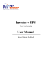
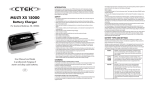
1
UPS Pure Sinewave UPS 1. INTRODUCTION 1. 1.1 General Description This UPS, a powerful all-in-one solution, delivers unsurpassed clean true sine wave output power and combines this with a powerful battery charging current. Applicable for any kind of loads such as air conditioner, home appliances, USER’S MANUAL consumer electronic and office equipments. This series features a durable & continuous 24 operation. The built-in intelligent charger automatically charges any type of batteries 1.6K / 3.2K / 5KVA 6.4K / 8K/ 10KVA without the risk of overcharge. The compact & modular design makes utility interactive installations easier and more cost effective. It is a high quality product that offers the best price/performance ratio in the industry. 1.2 Key features Multiple microprocessor design base. User Friendly LCD Control Panel Compatible with both linear & non-linear load. Powerful charger to support batteries of 500AH up. 24 hours operation for Long Time Back Up DC start. THD less than 3%. High efficiency design to save electricity. Design to operate under harsh environment 1.3 Important Notices 1. Read instructions carefully before operating the UPS. 2. UPS power connect instruction should be followed. 3. Please don‘t open the case to prevent danger. 5. Retain the load within the rating of UPS to prevent faults. 6. Keep the UPS clean and dry. 2. SAFETY INSTRUCTIONS 2.3 Installation 1. Connect the UPS system only to an earthed shockproof socket outlet. RISK OF ELECTRIC SHOCK 2. Place cables in such a way that no one can step on or trip over them. Do not open unless for Qualified Personnel Please read carefully the instructions before working on this product. 2.4 Operation 1. Do not disconnect the mains cable on the UPS system or the building wiring socket outlet during operations since this would cancel the protective earthing of the UPS system and of all connected loads. 2.1 Transporting 2. The UPS has its own power source (batteries). The output terminals may be live even when the UPS is not connected to the AC supply. 1. Disconnect all power cables if necessary. 2. Be careful not to damage the UPS while transporting. 3. Ensure that no fluids or other foreign objects can enter the UPS system. 3. Don‘t move the UPS upside down. 4. Please transport the UPS system only in the original packaging to protect it 2.5 Maintenance and Service against shock and impact. 1. wiring socket outlet), components inside the UPS system are still connected 2.2 Positioning to the battery and are still electrically live and dangerous. 1. Do not put the UPS on rugged or declined surface. 2. Do not install the UPS system near water or in damp environments. 2. 4. Do not block off ventilation openings in the UPS system’s housing and don’t leave objects on the top of the UPS. Before carrying out any kind of servicing and/or maintenance, disconnect the batteries and verify that no current is present. 3. Do not install the UPS system where it would be exposed to direct sunlight or near heat. Even after the unit is disconnected from the mains power supply (building 3. Batteries may cause electric shock and have a high short-circuit current. Please take the precautionary measures specified below and any other measures necessary when working with batteries: 5. Keep the UPS far away from heat emitting sources. - remove wristwatches, rings and other metal objects 6. Do not expose it to corrosive gas. - use only tools with insulated grips and handles. 7. Ambient temperature : 0℃ - 40℃ 3. CABLE CONNECTION 4. SYSTEM DESCRIPTION 3.1 Inspection 4.1 Front Panel Description (1) 1. The system may be installed and wired only by qualified electricians in accordance with applicable safety regulations. 2. When installing the electrical wiring, please note the nominal amperage of your incoming feeder. 3. Inspect the packaging carton and its contents for damage. Please inform the vendor immediately if you find signs of damage. Please keep the packaging in a safe place for future use. 4. Please ensure that the incoming feeder is isolated and secured to prevent it from being switched back on again. 3.2 Connection (5) (7) (6) UPS Input and Output Connection: Connect the input and output wires to the corresponding input and output terminals according to the following diagram. (2) (3) (4) 1. LCD Display: indicates the UPS operation information, including UPS status, input/output voltage, input/output frequency, battery capacity, output load, temperature, etc. 2. Input: press to display Input Voltage and Frequency on the LCD Display. 3. Output: press to display Output Voltage and Frequency on the LCD Display. 4. Battery: press to display Battery Voltage and Load percentage on the LCD Display Terminal for Terminal for 120V System Models 230V System Models 5. Fault LED (red): indicates the UPS is in fault condition because of inverter shutdown or batteries needs to be replaced. 6. Back Up LED (yellow): To indicate the UPS is in battery back-up mode. 7. Normal LED (green): To indicate the UPS is operating normally. 4.2 Outline Description For 6.4KVA, 8KVA, 10KVA For 1.6KVA, 3.2KVA, 5KVA 5. UPS OPERATION 5.1 Check Prior to Start Up 6.2 Normal Operation There are two main loops when AC utility is normal: the AC loop and the 1. Ensure the UPS is in a suitable positioning. 2. Check input cord is secured. 3. Make sure the load is disconnected or in the “OFF” position. 4. Check if input voltage meets the UPS rating required. battery charging loop. The AC output power comes from AC utility input and passes through static switch to support power to load. The battery charging voltage comes from AC utility input and converted by AC/DC charger to support battery-charging power. 5.2 Storage Instruction Disconnect input power in rear panel if you will not use it for long period. If the UPS is stored over 3 months, please keep supplying power to the UPS for at least 24 hours to ensure battery fully recharged. 6. OPERATION MODES OF THE UPS 6.3 AC Utility Failure (Battery Mode) 6.1 UPS System Block Diagram The AC output comes from battery, passing through DC/AC inverter and static switch within the battery backup time. 7. SPECIFICATION OF UPS