1
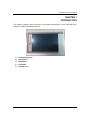
GOT3846T-832 All-in-One 8.4” SVGA TFT Fanless Compact-Size PANEL PC User’s Manual Disclaimers This manual has been carefully checked and believed to contain accurate information. Axiomtek Co., Ltd. assumes no responsibility for any infringements of patents or any third party’s rights, and any liability arising from such use. Axiomtek does not warrant or assume any legal liability or responsibility for the accuracy, completeness or usefulness of any information in this document. Axiomtek does not make any commitment to update the information in this manual. Axiomtek reserves the right to change or revise this document and/or product at any time without notice. No part of this document may be reproduced, stored in a retrieval system, or transmitted, in any form or by any means, electronic, mechanical, photocopying, recording, or otherwise, without the prior written permission of Axiomtek Co., Ltd. Copyright 2012 Axiomtek Co., Ltd. All Rights Reserved Sep. 2012, Version A1 Printed in Taiwan ii Safety Precautions Before getting started, please read the following important safety precautions. 1. 2. 3. 4. 5. 6. 7. The GOT3846T-832 does not come equipped with an operating system. An operating system must be loaded first before installing any software into the computer. Be sure to ground yourself to prevent static charge when installing the internal components. Use a grounding wrist strap and place all electronic components in any static-shielded devices. Most electronic components are sensitive to static electrical charge. Disconnect the power cord from the GOT3846T-832 before any installation. Be sure both the system and external devices are turned OFF. A sudden surge of power could ruin sensitive components that the GOT3846T-832 must be properly grounded. The brightness of the flat panel display will be getting weaker as a result of frequent usage. However, the operating period varies depending on the application environment. Turn OFF the system power before cleaning. Clean the system using a cloth only. Do not spray any liquid cleaner directly onto the screen. The GOT3846T-832 comes with a touchscreen. Although the touchscreen is chemical resistant, it is recommended that you spray the liquid cleaner on a cloth first before wiping the screen. In case your system comes without the touchscreen, you must follow the same procedure and not spray any cleaner on the flat panel directly. Avoid using sharp objects to operate the touchscreen. Scratches on the touchscreen may cause malfunction or internal failure to the touchscreen. The flat panel display is not susceptible to shock or vibration. When assembling the GOT3846T-832, make sure it is securely installed. Do not open the system ’s back cover. If opening the cover for maintenance is a must, only a trained technician is allowed to do so. Integrated circuits on computer boards are sensitive to static electricity. To avoid damaging chips from electrostatic discharge, observe the following precautions:Before handling a board or integrated circuit, touch an unpainted portion of the system unit chassis for a few seconds. This will help to discharge any static electricity on your body. When handling boards and components, wear a wrist-grounding strap, available from most electronic component stores. Trademarks Acknowledgments Axiomtek is a trademark of Axiomtek Co., Ltd. IBM, PC/AT, PS/2, VGA are trademarks of International Business Machines Corporation. ® Intel and Atom ™ are registered trademarks of Intel Corporation. MS-DOS, Microsoft C and Quick BASIC are trademarks of Microsoft Corporation. VIA is a trademark of VIA Technologies, Inc. SST is a trademark of Silicon Storage Technology, Inc. UMC is a trademark of United Microelectronics Corporation. Other brand names and trademarks are the properties and registered brands of their respective owners. iii Table of Contents Disclaimers .................................................................................................................................. ii Safety Precautions ...................................................................................................................... iii CHAPTER 1 1.1 1.2 1.2.1 1.2.2 1.2.3 1.3 1.4 1.5 INTRODUCTION ........................................................................................................ 1 General Description ................................................................................................... 2 Specifications ............................................................................................................. 3 Main CPU Board ........................................................................................................ 3 I/O System ................................................................................................................. 3 System Specification .................................................................................................. 4 Dimensions ................................................................................................................ 5 I/O Outlets .................................................................................................................. 7 Packing List................................................................................................................ 8 CHAPTER 2 2.1 2.2 2.3 2.3.1 2.3.2 2.4 2.5 2.5.1 2.5.2 2.6 2.7 2.8 2.9 HARDWARE INSTALLATION ................................................................................... 9 Open back cover ...................................................................................................... 10 CF card Installation .................................................................................................. 11 Serial Ports Interface ............................................................................................... 13 COM1&COM2 Connector ........................................................................................ 14 COM3&COM4 Connector ........................................................................................ 14 Ethernet ................................................................................................................... 15 Mountings: Panel / Wall / Desktop / VESA .............................................................. 16 VESA-ARM/Wall-Mount ........................................................................................... 16 Panel-mount Kit Assembly ....................................................................................... 17 HDD Installation ....................................................................................................... 18 DRAM Installation .................................................................................................... 21 Wireless LAN Card Installation ................................................................................ 25 Power ....................................................................................................................... 27 CHAPTER 3 3.1 3.2 3.3 3.4 3.5 3.6 3.7 3.8 AMI BIOS SETUP UTILITY ..................................................................................... 29 Starting ..................................................................................................................... 29 Navigation Keys ....................................................................................................... 30 Main Menu ............................................................................................................... 31 Advanced Menu ....................................................................................................... 32 Chipset Menu ........................................................................................................... 39 Boot Menu ................................................................................................................ 41 Security Menu .......................................................................................................... 42 Exit Menu ................................................................................................................. 43 CHAPTER 4 4.1 4.2 4.2.1 4.2.2 4.3 4.3.1 DRIVERS INSTALLATION ...................................................................................... 45 System ..................................................................................................................... 45 Touch Screen........................................................................................................... 46 Specification ............................................................................................................. 46 Driver Installation- Windows 7 ................................................................................. 46 Embedded O.S. ....................................................................................................... 49 WES 7 ...................................................................................................................... 49 iv GOT3846T-832 User’s Manual CHAPTER 1 INTRODUCTION This chapter contains general information and detailed specifications of the GOT3846T-832. Chapter 1 includes the following sections: General Description Specification Dimensions I/O Outlets Package List Introduction 1 GOT3846T-832 User’s Manual 1.1 General Description The GOT3846T-832 adopts a 8.4-inch SVGA TFT LCD with 450-nit brightness and an ® TM Intel Atom processor N2600 1.6 GHz to provide excellent computing performance and thermal resistance. This fanless platform is especially design ed for operating under heavy-duty environment including steel refinery, oil pipe, ship, machine maker operating systems and many more. Having below abilities makes GOT3846T-832 surely a most robust and cost-effective solution. Wide Operating Temperature Range GOT3846T-832 features a technology of wide operating temperature range wh ich allows it to work between -20 ° C to +55 ° C. It incorporates compact ID and fanless cooling ® TM system with a low power Intel Atom processor N2600 1.6 GHz, making the platform a power-efficient solution. Reliable and Stable Design The GOT3846T-832 adopts a fan-less cooling system, which makes it especially suitable for vibration-heavy environments, best for the transportation, ship, and industrial machinery markets. For high capacity storage requirement, GOT3846T-832 can work under 1.0G (5 ~ 500Hz, random for 2.5” HDD) in operation mode with a patent of anti-vibration design. The patent improves the system reliability and sustainability. WLAN Antenna Supported (optional) GOT3846T-832 has a PCI Express Mini Card slot for optional add-ons such as wireless LAN card for 802.11 b/g connections & 3G/GPRS application, and more. It also provides an optional fixed rotational W LAN antenna for wireless network connection. More Features GOT3846T-832 utilizes one 204-pin DDR3 800 SODIMM system memory max. up to 2GB, one SATA HDD and one CF. It provides over-current protection-fuse and a full set of I/O including RS-232, RS-232/422/485, USB 2.0, audio (line-out), Gigabit Ethernet and VGA. Additionally, this slim unit supports panel mount, wall mount (optional), VESA mount (optional) and desktop stand (optional). 2 Introduction GOT3846T-832 User’s Manual 1.2 Specifications 1.2.1 Main CPU Board CPU Intel○R AtomTM N2600 1.6GHz processor onboard System Chipset R Intel○ NM10 Express BIOS America Megatrends BIOS System Memory One 204-pin DDR3 800MHz SO-DIMM socket Maximum memory up to 2GB 1.2.2 I/O System Standard I/O 1 x RS-232/422/485, 3 x RS232 1 x Line-out Expansion 2x RJ45 for Giga Ethernet Audio 1x VGA Ethernet 4x USB 2.0 1 x Mini-card slot Storage 1 x 2.5” SATA HDD 1 x CompactFlash™ Type-II(optional) Power connector Phoenix power connector Introduction 3 GOT3846T-832 User’s Manual 1.2.3 System Specification 8.4” SVGA(800x600) LCD with LED backlight 5 wired resistive Touch Fanless Heat Dispensing Design IP65 aluminum front bezel Disk drive housing: Net Weight 3.4 Kgs (7.49 lb) Dimension (Main Body Size) One 2.5” SATA drive 248x 58.3x 183mm Operation Temperature -20℃ to 55℃ Relative Humidity 10% to 95% @ 40℃, Non-Condensing Power input 4 10~30VDC with phoenix power connector NOTE All specifications and images are subject to change without notice. NOTE If the operation temperature is higher than 40 ℃ , the wide temperature DRAM recommended to be used on the device. is Introduction GOT3846T-832 User’s Manual 1.3 Dimensions The following diagrams show the dimensions and outlines of GOT3846T-832. Introduction 5 GOT3846T-832 User’s Manual 6 Introduction GOT3846T-832 User’s Manual 1.4 I/O Outlets Please refer to the following illustration for I/O locations of the GOT3846T-832. Introduction 7 GOT3846T-832 User’s Manual 1.5 Packing List When you receive the GOT3846T-832, the bundled package should contain the following items: GOT3846T-832 unit x 1 Driver CD x1 Phoenix connector x 1 Panel mount kit x 6 Wall mount Kit x 1 Screws for HDD x 4 If you can not find the package or any items are missing, please contact Axiomtek distributors immediately. 8 Introduction GOT3846T-832 series User’s Manual CHAPTER 2 HARDWARE INSTALLATION The GOT3846T-832 provides rich I/O ports and flexible expansions for you to meet different demand, for example CF card. The chapter will show you how to install the hardware. It includes: CompactFlash™ Card Serial Port Ethernet Mounting Method Hard disk DRAM Wireless LAN Card Power Hardware Installation 9 GOT3846T-832 User’s Manual 2.1 Open back cover This section tells users how to open back cover. Please follow the steps below. Step 1 Unscrew 12 screws on the back cover. Please refer the photo below. Step 2 Remove the back cover. 10 Hardware Installation GOT3846T-832 series User’s Manual 2.2 CF card Installation The GOT3846T-832 provides one CF slot for users to install CompactFlash™ card. Please refer to the following instructions for installation: Step 1 Unscrew 12 screws on the chassis. Hardware Installation 11 GOT3846T-832 User’s Manual Step 2 Remove the chassis. . Step 3 12 Insert the card into the socket. Hardware Installation GOT3846T-832 series User’s Manual 2.3 Serial Ports Interface The GOT3846T-832 has four serial ports. COM1 is RS-232/422/485, while COM2, COM3, and COM4 are RS-232. The following table shows you the pin assignments of this connector: Description Function Jumper Setting JP9 JP7 JP8 JP9 JP7 JP8 JP7 JP8 RS-232 (Default) COM 1 RS-422 JP9 RS-485 Hardware Installation 13 GOT3846T-832 User’s Manual 2.3.1 COM1&COM2 Connector The COM1 and COM2 is a standard DB-9 connector. This connector is equipped with +5V level power capability on DCD and +12V level on RI by setting JP10 and JP11. The pin assignment of RS-232/RS-422/RS-485 is listed on the following table. If you need COM1 port to support RS-422 or RS-485 mode, please refer to Jumper Settings Pin RS-232 RS-422 RS-485 1 DCD TX- Data- 2 RXD TX+ Data+ 3 TXD RX+ N.C 4 DTR RX- N.C. 5 GND No use No use 6 DSR No use No use 7 RTS No use No use 8 CTS No use No use 9 RI No use No use COM1 (SBC87832) 1 6 2.3.2 5 10 COM3&COM4 Connector The COM3 and COM4 is a 2x5 pin box header. This connector is equipped with +5V level power capability on DCD and +12V level on RI by setting JP12 and JP13. The pin assignment of RS-232/RS-422/RS-485 is listed on the following table. If you need COM1 port to support RS-422 or RS-485 mode, please refer to Jumper Settings 14 Pin Signal Pin Signal 1 DCD 2 DSR 3 RXD 4 RTS 5 TXD 6 CTS 7 DTR 8 RI 9 GND 10 N.C. Hardware Installation GOT3846T-832 series User’s Manual 2.4 Ethernet The GOT3846T-832 is equipped with a high performance Plug and Play Ethernet interface, full compliant with IEEE 802.3 standard, and can be connected with a RJ-45 LAN connector. Please refer to detailed pin assignment list below: Pin Signal 1 TX+ (Data transmission positive 2 TX- (Data transmission negative) 3 Rx+(Data reception positive) 4 RJ45 termination 5 RJ45 termination 6 Rx- (Data reception negative) 7 RJ45 termination 8 RJ45 termination 1 2 3 4 5 6 7 8 RJ-45 Hardware Installation 15 GOT3846T-832 User’s Manual 2.5 Mountings: Panel / Wall / Desktop / VESA There are 4 application options for the GOT3846T-832, Panel/Wall/Desktop/VESA mountings. 2.5.1 VESA-ARM/Wall-Mount The GOT3846T-832 provides VESA mount: 75x75 mm . Screw four screws to fix the kit in the back chassis. 16 Hardware Installation GOT3846T-832 series User’s Manual 2.5.2 Panel-mount Kit Assembly The GOT3846T-832 is designed for panel mount application. To mount the GOT3846T832, the standard set of mounting kit (included in the system packaging) is neede d. Hardware Installation 17 GOT3846T-832 User’s Manual 2.6 HDD Installation The GOT3846T-832 provides a convenient Hard Disk Drive (HDD) bracket for users to install 2.5” SATA HDD. Please follow the steps: Step 1 Refer section 2.1 to open the back cover. Step 2 Unscrew 4 screws to take off the HDD bracket. Step 3 Fix the HDD on bracket by 4 screws. 18 Hardware Installation GOT3846T-832 series User’s Manual Step 4 Fix the HDD bracket into the cover, fasten the power and data cable in the cable tie, then plug the cables to connectors. Installation completes. Hardware Installation 19 GOT3846T-832 User’s Manual Data Powe r 20 Hardware Installation GOT3846T-832 series User’s Manual 2.7 DRAM Installation The GOT3846T-832 provides one 204-pin DDR3 SODIMM socket that support system memory up to 2GB. Please follow steps below to install the memory modules: Step 1 Refer to section 2.1 to open the back cover and find out DIMM socket on mainboard (SBC87832). Step 2 Stick the thermal pad on the main board and rip the red mylar from it. Hardware Installation 21 GOT3846T-832 User’s Manual Step 3 22 Insert the DRAM to the DIMM socket, and then push it down firmly until it is clipped by the socket. Hardware Installation GOT3846T-832 series User’s Manual Step 4 Rip the red mylar from DRAM bracket, then screw it into the chassis. Installation completed. Hardware Installation 23 GOT3846T-832 User’s Manual 24 Hardware Installation GOT3846T-832 series User’s Manual 2.8 Wireless LAN Card Installation The GOT3846T-832 provides one Mini card slot for user to install one wireless LAN card. W hen installing the wireless LAN card, refer to the following instructions and illustration: Step 1 Refer to section 2.1 to open the back cover and find out mini-card slot on mainboard. Step 2 Insert the wireless LAN card to the slot. P ush it down firmly until it is clipped by the slot. Hardware Installation 25 GOT3846T-832 User’s Manual Step 3 Find the built-in Antenna cable and connect it wireless LAN card. Step 4 Lift the rubber stopper from the top of back cover. Step 5 Install the antenna on the antenna connector. NOTE: Please have the extented bracket when using half-size mini card. 26 Hardware Installation GOT3846T-832 series User’s Manual 2.9 Power GOT3846T-832 equips with a phoenix type power connector. It adopts 10VDC to 30VDC. Please follow the signs on power connector to connect DC power source . +: Power positive G: Safty ground -:Power negative NOTE: The safty ground must be connected to ensure the uiit working appropriately. Hardware Installation 27 GOT3846T-832 User’s Manual MEMO: 28 Hardware Installation GOT3846T-832 series User’s Manual CHAPTER 3 AMI BIOS SETUP UTILITY This chapter provides users with detailed description how to set up basic system configuration through the AMIBIOS8 BIOS setup utility. 3.1 Starting To enter the setup screens, follow the steps below: Turn on the computer and press the <Del> key immediately. After you press the <Delete> key, the main BIOS setup menu displays. You can access the other setup screens from the main BIOS setup menu, such as the Chipset and Power menus. AMI BIOS Setup Utility 29 GOT3846T-832 User’s Manual 3.2 Navigation Keys The BIOS setup/utility uses a key-based navigation system called hot keys. Most of the BIOS setup utility hot keys can be used at any time during the setup navigation process. These keys include <F1>, <F10>, <Enter>, <ESC>, <Arrow> keys, and so on. Note: Some of navigation keys differ from one screen to another. Left/Right The Left and Right <Arrow> keys allow you to select a setup screen. Up/Down The Up and Down <Arrow> keys allow you to select a setup screen or sub-screen. + Plus/Minus The Plus and Minus <Arrow> keys allow you to change the field value of a particular setup item. Tab The <Tab> key allows you to select setup fields. F1 The <F1> key allows you to display the General Help screen. F10 The <F10> key allows you to save any changes you have made and exit Setup. Press the <F10> key to save your changes. Esc The <Esc> key allows you to discard any changes you have made and exit the Setup. Press the <Esc> key to exit the setup without saving your changes. Enter 30 The <Enter> key allows you to display or change the setup option listed for a particular setup item. The <Enter> key can also allow you to display the setup sub- screens. AMI BIOS Setup Utility GOT3846T-832 series User’s Manual 3.3 Main Menu W hen you first enter the Setup Utility, you will enter the Main setup screen. You can always return to the Main setup screen by selecting the Main tab. There are two Main Setup options. They are described in this section. The Main BIOS Setup screen is shown below. System Time/Date Use this option to change the system time and date. Highlight System Time or System Date using the <Arrow> keys. Enter new values through the keyboard. Press the <Tab> key or the <Arrow> keys to move between fields. The date must be entered in MM/DD/YY format. The time is entered in HH:MM:SS format. AMI BIOS Setup Utility 31 GOT3846T-832 User’s Manual 3.4 Advanced Menu Launch PXE OpROM Use this item to enable or disable the boot ROM function of the onboard LAN chip when the system boots up. Launch Storage OpROM Enable or disable boot option for legacy mass storage devices with Option ROM. The Advanced menu allows users to set configuration of the CPU and other system devices. You can select any of the items in the left frame of the screen to go to the sub menus: ► ACPI Settings ► CPU Configuration ► IDE Configuration ► USB Configuration ► NCT6627UD Superior IO Configuration ► NCT6627UD HW Monitor ► JMB36X ATA Controller Configuration For items marked with “”, please press <Enter> for more options. 32 AMI BIOS Setup Utility GOT3846T-832 series User’s Manual ACPI Settings You can use this screen to select options for the ACPI Settings, and change the value of the selected option. A description of the selected item appears on the right side of the screen. ACPI Sleep State Use this item to select the highest ACPI sleep state the system will enter . AMI BIOS Setup Utility 33 GOT3846T-832 User’s Manual CPU Configuration This screen shows the CPU Configuration, and you can c hange the value of the selected option. Hyper Threading Technology Use this item to enable or disable Hyper-Threading Technology, which makes a single physical processor perform multi-tasking function as two logical ones. Execute Disable Bit This item helps you enable or disable the No-Execution Page Protection Technology 34 AMI BIOS Setup Utility GOT3846T-832 series User’s Manual IDE Configuration SATA Controller(s) The optional settings are: [Disabled]; [Enabled]. Configure SATA as The optional settings are: [IDE]; [AHCI]. AMI BIOS Setup Utility 35 GOT3846T-832 User’s Manual USB Configuration You can use this screen to select options for the USB Configuration, and change the value of the selected option. A description of the selected item appears on the right side of the screen. 36 Legacy USB Support The optional settings are: [Auto]; [Disabled]; [Enabled]. AMI BIOS Setup Utility GOT3846T-832 series User’s Manual NCT6627UD Super IO Configuration You can use this screen to select options for the Super IO Configuration, and change the value of the selected option. A description of the selected item appears o n the right side of the screen Serial Port Configuration Use this item to set parameters of serial port 0~3. AMI BIOS Setup Utility 37 GOT3846T-832 User’s Manual PC Health Status This screen shows the Hardware Health Configuration, and a description of the selected item appears on the right side of the screen. 38 AMI BIOS Setup Utility GOT3846T-832 series User’s Manual 3.5 Chipset Menu The Chipset menu allows users to change the advanced chipset settings. You can select any of the items in the left frame of the screen to go to the sub menus: Host Bridge Host Bridge For items marked with “”, please press <Enter> for more options. South Bridge South Bridge For items marked with “”, please press <Enter> for more options. AMI BIOS Setup Utility 39 GOT3846T-832 User’s Manual Memory Frequency and Timing This item is for memory frequency and timing settings. P ress <Enter> to go to the sub menu. 40 AMI BIOS Setup Utility GOT3846T-832 series User’s Manual 3.6 Boot Menu The Boot menu allows users to change boot options of the system. Boot Settings Configuration Setup Prompt Timeout Use this item to set number of seconds to wait for setup activation key. Bootup NumLock State Use this item to select the power-on state for the NumLock.. The optional settings are: [On]; [Off]. GateA20 Active If Upon Request is selected, GA20 can be disabled using BIOS services. If Always is selected, disabling G20 is not allowed; this option is useful when any RT code is executed above 1MB. Option ROM Messages Set display mode for option ROM. Configuration options are Force BIOS and Keep Current. Interrupt 19 Capture If this item is enabled, this function makes the option ROM to trap Interrupt 19. Boot Option Priorities These are settings for boot priority. Specify the boot device priority sequence from the available devices. AMI BIOS Setup Utility 41 GOT3846T-832 User’s Manual 3.7 Security Menu The Security menu allows users to change the security settings for the system. 42 Administrator Password This item indicates whether an administrator password has been set. If the password has been installed, Installed displays. If not, Not Installed displays. User Password This item indicates whether a user password has been set. If the password has been installed, Installed displays. If not, Not Installed displays. AMI BIOS Setup Utility GOT3846T-832 series User’s Manual 3.8 Exit Menu The Save & Exit menu allows users to load system configuration with optimal or failsafe default values. Save Changes and Exit When you have completed the system configuration changes, select this option to leave Setup and reboot the computer so the new system configuration parameters can take effect. Select Save Changes and Exit from the Exit menu and press <Enter>. Select Ok to save changes and exit. Discard Changes and Exit Select this option to quit Setup without making any permanent changes to the system configuration. Select Discard Changes and Exit from the Exit menu and press <Enter>. Select Ok to discard changes and exit. Save Changes and Reset When you have completed the system configuration changes, select this option to leave Setup and reboot the computer so the new system configuration parameters can take effect. Select Save Changes and Reset from the Save & Exit menu and press <Enter>. Select Yes to save changes and reset. AMI BIOS Setup Utility 43 GOT3846T-832 User’s Manual 44 Discard Changes and Reset Select this option to quit Setup without making any permanent changes to the system configuration and reboot the computer. Select Discard Changes and Reset from the Save & Exit menu and press <Enter>. Select Yes to discard changes and reset. Save Changes When you have completed the system configuration changes, select this option to save changes. Select Save Changes from the Save & Exit menu and press <Enter>. Select yes to save changes. Discard Changes Select this option to quit Setup without making any permanent changes to the system configuration. Select Discard Changes from the Save & Exit menu and press <Enter>. Select Yes to discard changes. Restore Defaults It automatically sets all Setup options to a complete set of default settings when you select this option. Select Restore Defaults from the Save & Exit menu and press <Enter>. Save as User Defaults Select this option to save system configuration changes done so far as User Defaults. Select Save as User Defaults from the Save & Exit menu and press <Enter>. Restore User Defaults It automatically sets all Setup options to a complete set of User Defaults when you select this option. Select Restore User Defaults from the Save & Exit menu and press <Enter>. Boot Override Select a drive to immediately boot that device regardless of the current boot order. AMI BIOS Setup Utility GOT3846T-832 series User’s Manual CHAPTER 4 DRIVERS INSTALLATION 4.1 System GOT3846T-832 supports Windows 7 32-bit and WES 7. To facilitate the installation of system driver, please carefully read the instructions in this chapter before start installing. 1. Insert Driver CD and select the “\Drivers”. 2. Select all files and follow the installing procedure. Installation of Drivers 45 GOT3846T-832 User’s Manual 4.2 Touch Screen The GOT3846T-832 uses the 5-wire analog resistve. There are the specification and driver installation which are listed below. 4.2.1 Specification Touch Screen 5-wire Analog Resistive type Touch Screen Controller PenMount 6000 USB Touch Screen Controller IC Communications USB interface Baud Rate 19200 baud rate fixed Resolution 800 x 600 Power Input 5V Power Consumption Active: 24.6mA / Idle Mode: 13.4mA 4.2.2 Driver Installation- Windows 7 The GOT3846T-832 provides a touch screen driver that users can install it under the operating system W indows 7. To facilitate installation of the touch screen driver, you should read the instructions in this chapter carefully before you attempt installation. 1. Insert Driver CD and follow the path to select the “\Drivers\Step 5 - Touch”. 2. Follow the installing procedure and press OK. 46 Installation of Drivers GOT3846T-832 series User’s Manual 3. Click Start menu and select “PenMount Utilities”; and then, a “PenMount Control Panel” pops out. 4. Select the “Standard Calibrate” tab. Installation of Drivers 47 GOT3846T-832 User’s Manual 5. Calibration: To adjust the display with touch panel, click “Calibration” and follow the calibrate point to do calibration; there are five points on screen for calibration. 6. 48 Press OK. Installation of Drivers GOT3846T-832 series User’s Manual 4.3 Embedded O.S. The GOT3846T-832 provides the W indows 7 Embedded. The O.S. is supported devices which are listed below. 4.3.1 WES 7 Here are supported onboard devices: Onboard Multi I/O SATA HDD USB PS2 Keyboard and mouse CRT/LCD display 10/100/1000 base-T Ethernet Compact Flash Onboard Audio Touch Screen PenMount Touch screen Before you can use and calibrate it, here is what you should do: 1. Set up Penmount touch device driver by executing C:\Penmount\ Windows 2000-XP V5.0\setup.exe. When the installation is finished, an icon “PM” appears on the Taskbar. 2. Calibrate Penmount touch by clicking on the “PM” icon, and the go on the calibration. 3. Restart the computer. Installation of Drivers 49 GOT3846T-832 User’s Manual MEMO: 50 Installation of Drivers