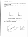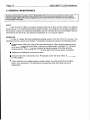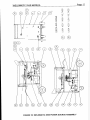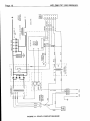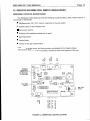
1
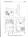
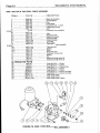
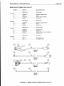
WELDING INDUSTRIES OF AUSTRALIA
A DIVISION OF WELDING INDUSTRIES LTD
ACN 004 547 l 1 l
Head Office and International Sales
5 Allan Street, Melrose Park
South Australia, 5039
Telephone (08) 8276 6494
Facsimile (08) 8276 6327
www.weldingindustries.corn.au
[email protected]
OWNERS MANUAL
WELDMATIC 255s
MODEL NO. CP107-0, REV. A
WITH W42-0 WIREFEEDER
~
l
09/2000
~
~
~
QUALITY WELDING PRODUCTS, SYSTEMSAND SERVICE
8t 7
?!l/[
Page 2
WELDMATIC 255s MANUAL
The information contained in this manual is setout to enable you to properly maintain your
new equipment and ensure that you
obtain maximum operating efficiency.
Pleaseensure that this information is kept in asafeplace
for ready reference when
required at any future time .
When requesting spare parts. please quote the model and serial number of
the machine
and part number of the item required. All relevant numbers are shown in lists contained in this
manual. Failure to supply this information may result in unnecessary delays in supplying the
correct parts.
SAFETY
Before this equipment is put into operation, the Safe Practices section at the back of the
manualmust be read completely. This will help to avoidpossibleinjuryduetomisuseor
improper welding applications
.
PLASTIC HANDLE
Please note that the handle fitted to the WELDMATIC W42-0 WIREFEEDER is intended
for carrying the machine by hand only
.
DO NOT use this handlefor suspending or mounting the machine in anyother manner.
~
CONTENTS
Sec .1 ............ Introduction................................................................... P.3
. . ......................................................................
P.3
Sec.2 ............ Recelvmg
Sec.3 ............ Specifications................................................................ P.4
Sec.4 ............ Control Locations. Power Source and Wirefeeder
........P.5
Sec.5 ............ Installation..................................................................... P.6
Sec.6 ............ Normal Welding Sequence........................................... P.9
Sec.7 ............ Basic Welding Information ............................................ P.10
Sec.8 ............ General Maintenance.................................................... P.12
Sec.9 ............ Trouble Shooting........................................................... P.13
Sec .10 .......... Service Information. Power Source............................... P.15
Sec.ll.......... Parts List. Power Source............................................... P.16
Sec.12 .......... Service Information. Wirefeeder .................................... P.19
Sec.13 .......... Parts List. Wirefeeder .................................................... P.20
Sec 14 .......... Safe Practices............................................................... P.26
FIGURES
P
Fig.1.............. Control Locations. Power Source and Wirefeeder
........P.5
Fig2 .............. Connection of Supply Cable
.......................................... P.6
Fig.3.............. Remote Wirefeeder Connections.................................. P.7
Fig.4.............. Positive wire Connection .............................................. P.8
Fig.5 .............. Negative Wire Connection............................................ P.8
Fig.6 .............. "Good" Weld.................................................................. P.11
....................................................................
.11
Fig.7
Weld
.............. "Bad"
..
Fig.8.............. Gun Posltlon
................................................................. P.11
Fig.9.............. Solid State Relay Control Board................................... P.15
............................................... P.17
Fig.10............ Power Source Assembly
Fig.11............ CP107-0 Circuit Diagram .............................................. P.18
.................................................
P.19
Fig.12............ Wirefeed Control Board
Fig.13............ Wirefeeder Assembly.................................................... P.21
Fig.l4 ............ W42-0 Circuit Diagram (With Lead Kit)......................... P.22
Fig.15............ Gun Cable Assembly.................................................... P.23
Fig.16............ Wire Drive Assembly
..................................................... P 2 4
Fig.l7 ............ AM283 Inter-connecting LeadKit .................................. P.25
WELDMATIC 255s MANUAL
Page
- 3
1. INTRODUCTION
Gas Metal Arc Welding (G.M.A.W.) is a welding process where a consumable wire is fed
by motor driven drive rollers to a welding gun, and where welding current is supplied from the
welding power source. The welding arc is struck between
the work piece and the end of the
wire, which melts into the weld pool. The arc and the weld pool are shielded by gas flow from
the gun, or in the case of "self shielded" wires, by gases generated by
the wire core.
By selection of the correct wire composition, diameter and shielding gas, G.M.A.W. canbe
used for applications ranging from sheetmetal to heavy plate, and metals ranging from carbon
steel to aluminium alloys.
TheWELDMATIC 255s hasbeendesigned to beusedwithconsumable
wires in the
range from 0.6mm to 1.2mm diameter. The smaller wire sizes are used when welding at lower
currents, such as sheet-metal applications. Increasing the wire diameter permits higher welding
currents to be selected.
A common application of G.M.A.W. is
for weldingMildSteel. In this application, a Mild
Steel solid consumable such as AUSTMIG ES6 is used with a shielding gas of Argon mixed with
5 - 25%CarbonDioxide.Alternatively,Flux-coredconsumablesare
available in both gas
shielded, and 'gasless' self shielding types.
Stainless steel
and
Aluminium
can
be
welded
with G.M.A.W. using the correct
consumable wire andshielding gas.
2. RECEIVING
Check the equipment received against the shipping invoice to make sure the shipment is
completeandundamaged. If anydamagehasoccurred
in transit, pleaseimmediately notify
your supplier.
The CP107-0 package contains;
WELDMATIC 255s Power source.
W42-0 Enclosed Wirefeeder (with Controls).
AM283-0/8 Inter-connecting Lead Kit, 8 metre.
BEXT2-4E310AE BERNARD Gun cable, 3 metre, Euro connector.
WGAC24 Regulator and Flowgauge. (Argon)
(This) Owners Manual.
~
Paae 4
WELDMATIC 255s MANUAL
Y
3. SPECIFICATIONS
Manufactured to Australian standard AS1 966.1-1 985
Rated to ISOAEC 60974-1 (IO minute duty cycle)
WELDING INDUSTRIES of AUSTRALIA
Weldmatic 255s
Made in Australia
m
1-
”
-
RATED TO
ISOAEC 60974-1
0
N803
W7N3WR
I
I
I
Under ISO/IEC 60974-1,dutycycle
is defined as theratio of arcing time to anoperating
time of 10 minutes, expressed as a percentage.
Note.Themachinehasbeenshippedwith
a 15 Ampplug fittedto allow initial
commissioning only.
To obtain rated output current from the WELDMATIC 255S, the 25 Amp flexible supply
cable must be fitted with a
3 pin plug that is rated for at least
25 Amp, and connected to a
correctly installed power outlet of at least 25 Amp.
Page 5
WELDMATIC 255s MANUAL
4. CONTROL LOCATIONS. POWER SOURCE ANDWIREFEEDER
B
POWER SOURCE
WIREFEEDER
l
~:
l.
FIGURE 1. CONTROL LOCATIONS. POWER SOURCE AND WIREFEEDER
1. POWER ON INDICATOR
This is illuminatedwhen the wirefeeder is energised, that is when electrical mains power is
connected to the welding power source.
2. COARSE VOLTAGE CONTROL
This switch provides Coarse adjustment ofthe Output Welding Voltage overthree ranges,
Low, Medium and High.
3. FINE VOLTAGE CONTROL
This control provides Fine adjustment of the Output Welding voltage. Rotating the control
in a clockwise direction will increase the output voltage.
,
l
4. WIRE SPEED CONTROL
This control provides adjustment of the wirefeed speed. Rotating the dial in a clockwise
direction will increase the wirefeed speed, thereby increasingthe welding current.
5. SPOT TIME CONTROL
When operating the machine in Spot Weld mode, this control will vary the spot weld time.
Rotating the dial in a clockwise direction will increase the spot weld time, in the range 0.5 - 2.5
seconds. If the Spot Weld mode is not required this feature may be turned off by rotating the
control anti-clockwise until it 'clicks' into the minimum position.
6. INTERVAL CONTROL
Whenoperating the machine in CycleArcmode this controlsets the period between
welds. The spot time control sets the welding period. Rotating the dial in a clockwise direction
will increase the interval time, in the range 0.5 - 2.5 seconds. If the Cycle Arc mode is
not
required this feature may be turned off by rotating both controls fully anti-clockwise.
7. WIREFEEDER FUSE
This 5 Amp standard action fuse protects the 30Vac Wirefeeder supplycircuit.
WELDMATIC 255s MANUAL
Page
- 6
5. INSTALLATION
CONNECTION TO ELECTRICAL MAINS POWER SUPPLY
I
NOTE. All
l
electrical work shall only be undertakenby a qualified electrician.
D
l
The WELDMATlC 2558 is factory fitted with a 3 metre,
3 core,25Ampsmainspower
supply cable with a moulded 3 pin, 15 Amps, Single Phase plug.
Note : The 15 Amp plug is fitted to allow initial commissioning only.
The minimum capacity of the mains wiring and power outlet supplying a welder isselected
according to the effective primarycurrent of the machine. The effective primary current
for a
Weldmatic 255s is 25 Amps.
To obtain rated output current from the WELDMATIC 255S, the 25 Amp flexible supply
cable must be fitted with a 3 pin plug that is rated for at least 25 Amp, and connected
to a
correctly installed power outlet of at least
25 Amp.
Note : 25 Amps plugs and sockets are not commercially available. A 32 Amps, 3 pin plug
is available from yourWlA distributor. WIA Part Number
for this plug is CL156P332.
TheminimumrecommendedcircuitbreakerratingforaWeldmatic
255s is 25 Amps.
Note : The tripping time of a typical 25A circuit breaker can limit the duty cycle available the
from
Weldmatic 255s. A higher rated circuit breaker can be selected,
but the mains wiring capacity
mustbe increased to suit. The current rating of the mainscabledependsoncable
size and
method of installation. Referto AS/NZS 3008.1, Table9.
If it becomes necessary to replace the mains flexible supply cable, use only cable
with
correct current rating. Access to the machine supply terminals is gained by removing the power
source left hand side panel. (Power source viewed from front). Pass the cable through the bush
fitted to the machine back panel. The cables are terminated at the terminal block as shown
in
Figure 2. Tighten the cable clamp leaving just sufficient slack in the cableso that the terminated
wires are not in tension.
.LOW WIRE
EARTH CONNECTION
l
T
Rk
1-L
I / I
BLUEmEJ1 i
’
\
PLASTIC BUSH
BACK PANEL
L 3 CORE POWER CABLE
B R O W WIRE
TERMlNAL BLOCK
FIGURE 2. CONNECTION OF SUPPLY FLEXIBLE CABLE
FITTING THE GAS BOTTLE
Depending on configuration of the cylinder to be used, the gas flowmeter !regulator may
be fitted directly to the cylinder, or in conjunction with an elbow fitting.DO NOT apply any grease
to these joints, and tighten the nuts securely.
Fit the end Q%the gas inlet Rose from the inter-connecting leadkit to the connector supplied
with the flow regulator, and secure withthe clamp also supplied.
WELDMATIC 175s MANUAL
Paae 7
U
5.3 FITTING THE GAS BOTTLE
Fit the gas regulator to the gas
cylinder. DO NOT apply oil or grease to these
of the
connections. Fit the gas connector supplied with the regulator to the gas hose
welder, and secure it with the '0' clip supplied.
Always ensure the gas regulator adjusting
knob is fully released before opening the
gas cylinder valve. Failureto observe this practice can result in damage to the regulator.
5.4 FITTING THE GUNCABLE
Theguncableisattachedtothepowersourceviaa'Euro'adaptorwhich
incorporates all required connection points for
welding current, shielding gas and gun
switch control.
To fittheguncable,engagethematingpartsofthemaleandfemaleEuro
connectors, then rotate the locking ring clockwise to firmly secure the connection.
5.5 FITTING THE CONSUMABLE WIRE
The quality of the consumable wire greatly affects how reliably a gas metal
arc
WIA
welder will operate.For best results when welding mild steel, we recommend quality
AUSTMIG ES6. Dirty, rusty or kinked wire will not feed smoothly through the gun cable
andwillcauseerraticwelding.Depositsfrom
thewirewillclogtheguncableliner
requiring it to be replaced prematurely.
Place the spool of welding wire onto the spool holder. The location pin should mate
with a hole provided on the wire spool
body. Fit the spool retaining 'R' clip supplied.
Check the adjustment of the spool brake, which should be set to prevent over-run of the
wire spool at the end of a weld, without unduly loading the wirefeed motor. The braking
can be adjusted by theNyloc nut using a 15/16"AF or 24mm socket wrench.
5.6 FEEDING THE CONSUMABLEWIRE
Openthe two rolldrivemechanismbydrawingthepressurespringoutwards,
allowing the upper roller assembly to be rotated away from the driven roller. The end of
the welding wire can now be passed through the inlet guide, over the bottom driven
roller, and into the gun cable assembly.
Check that the drive roller groove
is correct for the wire in use. The appropriate size
is stamped on the visible sideof the installed roller. Part numbers for alternate size drive
rollers are shown in Section-l1.
Check also that the correct size contact tip is fitted to the gun. Gun part numbers
are shown in Section12.
Return the top roller to the closed position and, with the machine energised, close
the gun switch to feed wire through the gun
cable. Adjust the compression screw to
provide just sufficient clamping of the drive rolls drive to achieve constant wirefeed. Do
not over tighten the compressionscrew, as the consumable wire can be crushed leading
to erratic wirefeed.
Page 8
WELDMATIC 255s MANUAL
OUTPUT VOLTAGE POLARITY.
Thedesignof
the WELDMATIC 255s allowsexternalselection
polarity.
of the output voltage
POSITIVE WIRE
Most solid wire G.M.A.W. is carried out with the work piece Negative and
the welding
consumable wire Positive.
To set the machine for this condition, insert the ‘WORK lead plug into the (-) output socket
on the front of the power source. Insert inter-connecting ‘WELD’ lead plug into the (+) output
socket onthe front of the power source. See Figure4 below.
NEGATIVE WIRE
Some ‘self-shielded’ flux cored consumables are intended to be operated with the work
piecePositive and the consurnablewire..Negative.Refer .to themanufacturers data for the
particular consumable to be used.
To set the machine for this condition; insert the .‘WORK lead plug into the (+) output
socket on the front of the power source. Insert inter-connecting ‘WELD’ lead plug into the (-)
output socket on the front of the power source. See Figure5 below.
L
FIGURE 4. POSITIVE WIRE
CONTROL LEAD
FIGURE 5. NEGATIVE WIRE
WELDMATIC 255s MANUAL
Page 9
6. NORMAL WELDING SEQUENCE
WELD START
Closing the welding gun switchinitiates this sequence ofevents:
The gas valve is energised, gas flow commences;
The power source contactor function is initiated. Welding
voltage is applied between the
work piece and the consumable wire.
The wire drive motor is energised. Wirefeed Commences andthe arc is established.
WELD END
Releasing the gunswitch.initiates.this sequenceof-events:
The wire drive motor is de-energised, and is dynamically brakedto a stop;
After a short pre-set period, known asthe ‘burn-back‘ time, the Power-source contactor
function is released. This period ensures that the consumable wire does not ‘freeze’ in
the weld pool. To adjustthe ‘burn-back’ time, refer toFigure/Section 12.
The gas valve is de-energised and the flow of shielding gas ceases.
l
I
l
l
Page I O
WELDMATIC 255s MANUAL
I
7. BASIC WELDING INFORMATION
CHOICE OF SHIELDING GAS
The choice of shielding gas is largely determined by
Many proprietary shielding gas mixtures are available.
the consumable wire to be used.
The recommendedshielding gases for use with the WELDMATIC 255s are :
Mild Steel ...................................
Argon + 5 to 25% Carbon Dioxide;
Aluminium ..................................
Argon;
Stainless Steel ...........................
Argon + lto 2% Oxygen.
Consult your gassupplier if more specificinformation is required.
SHIELDING GAS FLOWRATE
In G.M.A. welding, one of the functions of the shielding gas is to protect the molten weld
pool from the effects of oxygen in the atmosphere. Without this protection the weld deposit
becomes 'honeycombed'in appearance, an effect which is described as weld porosity.
In draft-free conditions the gas flow rate required to give adequate protection is typically
10 litredmin. In situations where drafts cannot be avoided, it may be necessary to increase this
rate and/or to provide screening of the work area.
Weld porosity canalso be causedbyairentering
the gasstreamthroughadamaged
hose, loose gas connection, or.from restriction in the nozzle, such as from excess build-up of
spatter.
ESTABLISHING A WELD SETTING
Once the consumable wire type, wire size and shielding gas have been chosen, the two
variables which are adjusted in order to obtain a stable arc are;
Wirefeed speed,
Welding arc voltage.
The wirefeed rate determines the welding current; increasing the feed rate increases the
current, and decreasing it decreases current. The selected wirefeed rate must be matched with
sufficient arc voltage;an increase of wirefeed rate requires an increase ofarc voltage.
If the voltage is too low the wire will stub and stutter, and there will not be a steady arc. If
the voltage is too high the arc will be long with the metal transfer within the arc occurring as a
series of large droplets.
The welding current should be chosen to suitthe thickness of the metal to be welded. It is
important to check that the deposited weld provides sufficient strength to suit the application.
l
~
I
WELDMATIC 255s MANUAL
Page 11
A "good" weld will have the characteristics illustrated in Figure 6. The weld has penetrated into
the parent metal, fusing the root of the joint where the two plates meet, andthe weld blends
smoothly into the side walls.
A "bad" weld is shown in Figure 7. The weld hasnot penetrated the joint root, and there is
poor side wall fusion. This lack of fusion would normally be corrected by increasing the arc
voltage, or by increasing both wirefeed rate and arc voltage to achieve a higher current weld
setting.
si L
FIGURE 6. "GOOD" WELD
FIGURE 7. "BAD" WELD
GUN POSITION
For "down hand" fillet welding, the gun is normally positioned as shown in Figure 8 below
with the nozzle end pointing in the direction of travel.
LA
4
F
v
FIGURE 8. GUN POSITION
Palcte 12
W
WELDMATIC 255s MANUAL
DUST
Care should be taken to prevent excessive build-up of dust and dirt within the welding
power source. It isrecommended that at regular intervals, accordingto the prevailing conditions,
the machine covers and enclosed wirefeeder coversbe removed and any accumulateddust be
removed bythe use of dry, low pressure compressed air, or a vacuum cleaner.
WIREFEED
In order to obtain the.mmt.satisfactory.,:welding-results from the G.M.A.W. process, the
wirefeed must be smooth andconstant. It is therefore important to observe the following points;
Keep the gun cable liner clear of dust and swarf build-up. When replacement becomes
necessary, fit only the correct liner to suit the gun cable model. See page23.The buildup of dust in a cable liner can be minimised by regular purging of theliner with dry
compressed air. This may be conveniently done eachtime the wire spool is replaced.
Replace the welding tip as it becomes worn.
Keep the wire drive mechanism clean. Periodically checkthe drive rollersfor wear and
for free rotation.
H
l
l
l
,
Check that the consumable wire spool holder rotates smoothly and that the braking
action is not excessive. This also may be conveniently done eachtime the wire is
replenished.
~
Page 13
WELDMATIC 255s MANUAL
~
W
~~
~~
~~
~
~
~
~
~~
9. TROUBLE SHOOTING
I
1
Power source has no power
l
I
Turn on mains supply switch
Check mains voltage, fuses or circuit breaker
I Check all primary connections in power source and inprimary plug
I
I
Power source has no output Check control lead
when gun switch is closed and Check
wirefeeder has no power but :
I
is plugged to front socket of power source
5A wirefeeder fuse on power source. Replace if blown
Check all connections to W42-10 circuit board in wirefeeder
l ) power source fan is running Check
2) wirefeeder power light is off
I
control lead for damage or broken solder joints in the 6 pin plug
Check controltransformer in power source for an input voltage of
.:
240Vac.and an output voltage of 32Vac. Replaceif faulty
. .
Replace W42-10 circuit board in wirefeeder
Power source has no output
Gun switch circuit incomplete. Check gun switch for continuity with
when gun switch is closed but:
Ohm meter when switch is pressed. Replace if faulty
l ) power source fan is running
Gun switch circuit incomplete. Check the 2 pin receptacles in euro
2) wirefeeder power light is on
adaptor of wirefeeder are making contact with
the 2 pins from the gun
3) there is no wirefeed
cable. If the pins have been accidentally pushed in, push and fix the
pins back in place with glue orLoctite
Check the two wires from wirefeed motor are connected to W42-10
circuit board
Replace W42-IO circuit board.
-.
~~~
~~
~~~
~
Power source has no output
Power source overheated. Allowthermostats to cool with fan on
when gun switch is closed but
Check control leadfor damage or broken solderjoints in the 6 pin plug
l)
power source fan is running
After cooling, check rectifier thermostat and inductancethermostat for
2) wirefeeder power light is on
open circuit. Replace if faulty
3) there is wirefeed
Check all connectionsto CP107-IO circuit boardin power source
ReDlace CP107-IO circuit board in Dower source
~~
~
~~
~
Replace W42-10 circuit board in wirefeeder
<
-.
Live output all the time when
power source is switched on
and gun switch is off
Check solidstate relay in power source. Switch off mains power and
disconnect wires from terminals 3 & 4 of solid state relay. Switch on
mains power andif output is still live, replace solid state relay
Replace CP107-IO circuit board in power
source
Replace W42-10 circuit board in wirefeeder
I
I
I
Power source has low weld
QUtpUt
Check all cable connections in power source for hot spots.
making
Check
welding
circuit
is
good electrical connection
l
Wirefeeder fuse blows
Check control lead for internal bridging of wires
instantly when power source
Replace W42-10 circuit boardin wirefeeder
is switched on
Replace CP107-IO circuit board in power source
Wirefeeder fuse blows after
Too much drive roller pressure on wire. Reduce pressure
a period of welding
Check gun linerfor build up of dirt or blockage. Replace if dirty
'~
Page
- 14
WELDMATIC 255s MANUAL
~~
TROUBLE SHOOTING cont.
Mains fuses blow or circuit
Check welding transformerfor a fault to earth. Replace if faulty
breaker trips instantly when
Check fan in power sourcefor short circuit or fault to earth. Replace
power source is switched on
if faulty
Check control transformer for short circuit or faultto earth. Replace
I if faulty
l
I
~
I
~~~
I
I
~
Mains fuses blow or circuit
Check welding transformerfor shorted turns. Replace if faulty
breaker trips instantly when
Check rectifier for shorted diodes. Replace if faulty
gun switch is closed
Mains fuses blow or circuit
Check that the recommended fuse or circuit breaker
rating has been
breaker trips when welding
used
UNSATISFACTORY WELDING PERFORMANCE AND RESULTS
Check if wire is slippingon roller assembly. Replace feed roll if worn
caused by poor wirefeed
j
Check if there is too much drive roller pressureon wire
Check spool holder is rotating smoothly
Check that gun liner is nottoo short and is fitted correctly. Refer to
page 23 for fitting instructions.
Constant poor arc
Check correct polarity
has
been
selected
characteristics
for work
and weld cables.
3
Refer to page 8
Check shieldinggas is correctfor the consumable in use
Check welding circuitis making good electrical connection
Check all connections in power source and wirefeeder
for hot spots
I
1
I
Porosity in weld caused by
lack of shieldinggasCheck
1
Check gas solenoid. Replace if faulty
that the correctgasflowratehasbeen
set
Check for leaks in gas hose. Replace if leaking
Check for leaks in gun cable,eg. O-rings. Replace if leaking
I
I
~~~
I Check nozzle is firmly attached
to gun and that no air is being drawn in
I
I
l
~
Page 15
WELDMATIC 255s MANUAL
I O . SERVICE INFORMATION. POWER SOURCE
SOLID STATE RELAY CONTROL BOARD CP107-10
The Solid State RelayControlboardandassociated
Solid State Relay provides the
following functions, when Power Sourceis connected to Wirefeeder.
m Welding transformer ON/OFF control in response to an output from the wirefeed control
board, (the contactor function).
m Output voltage control by means of Phase-shiftingof the Welding transformer primary
voltage, as adjusted by the wirefeeder front panel "FINE VOLTAGE SELECTION"knob.
Connectionsito the.board-are:detailed.in the:drawing below.
RECTIFIER THERMOSTAT
CONTROL
qF
SOLID STATE RELAY (-V€)
SOLID STATE RELAY (+VE)
FINE VOLTAGE (W)
FINE VOLTAGE (CW)
30v
MOUNTING HOLES
I
1
#$oooo@na
M
m
$ii'Q
l a
0
0 (J(J0
~ € l l 00
a (d~ ~
L.E.D. IS LIT WHEN FINE
VOLTAGE POTENTIOMETER
[CIRCUITISCOMPLETE
FIGURE 9. SOLID STATE RELAY CONTROL BOARD
Page 16
WELDMATIC 255s MANUAL
11. PARTS LIST
WELDMATIC 255s POWER SOURCE
ITEM # ............... PART # ...........................
1 ...........................
Includes
1.l........................
1.2 ........................
1.2.1 .....................
1.2.2 .....................
1.2.3 .....................
1.2.4 .....................
DESCRIPTION
CP107-33............................
Rectifier Assembly
CP106-0/1 ...........................
CP107-41............................
CP107-IO ............................
CP106-0/2...........................
CP107-41/2.........................
CP107-41/1.........................
Rectifier Assembly withThermal overload
Solid State Relay Heatsink Assy (240V)
PCB Assy SolidState Relay Control
Solid State Relay 240V
Heatsink
Dust Shield
2 ........................... CP107-30L.......................... Welding Transformer Assembly inc.Wire Loom
3 ......................... ..CP107-42............................
Inductance Assembly inc. Overload
4 ...........................
CP107-43....................._........Capacitor Bank
Includes
Mounting Bracket
4.1 ........................ CP43-25..............................
4.2 ...................... ..CP102-12/8 .........................
Capacitor (4)
4.3 ........................ CP105-31/2......................... Capacitor Rail (2)
5 ........................... CP106-20/2 .........................
6 ...........................
CP43-23..............................
Includes
6.1 ...................... ..CP42-24/6...........................
I
Discharge Resistor(4)
Base Assembly
Castor Wheel(2)
7 ...........................
8 ...........................
9 ...........................
10 .........................
11 .........................
12 .........................
13 .........................
14 .........................
15 .........................
16 .........................
17 .........................
18 .........................
19 .........................
20 .........................
21 .........................
22 .........................
23 .........................
24 .........................
25 .........................
26 .........................
27 .........................
28 .........................
Includes
28.1 ......................
CPIO7-22Y .........................
CP4 3-21Y
...........................
CP43-24Y ...........................
CP106-25Y .........................
CP44-22..............................
CP42-0/3.............................
MC11-53/6 ..........................
MK6/3 .................................
W1-23 .................................
F3AG5A ..............................
CP107-012 ...........................
CP107-0/1...........................
CPI 07-44 ............................
CP107-45............................
CPI 07-46 ............................
CPlO7-52 ............................
CP107-53 ............................
CP107-54............................
CPI 07-47 ............................
W39-0/1 ..............................
CP107-39............................
CP107-49............................
Front Panel
Back Panel
Side Panel (2)
Top Panel
Shelf Panel
Rubber Tyre Wheel (2)
Ratchet Cap (2)
Terminal Block,3 position
Fuse Holder
Fuse 5 Amp Standard Action
Cooling Fan
Auxiliary Transformer
Cable Inductor Endto Capacitor Neg. Rail
Cable Transformerto Rectifier AC
Cable Capacitor Pos.Rail to Pos. O/P Terminal
Cable Limit Ind.Start to Rectifier Neg.
Cable Capacitor Pos.Rail to Rectifier Pos.
Cable InductorStart to Neg. O/P Terminal
Busbar Transformerto Rectifier AC
Switch Coarse
Loom Assembly -High Voltage(Not Shown)
Loom Assembly -Low Voltage (Not Shown)
CP107-49/1 .........................
Socket 6 pin
29 .........................
30 .........................
31 .........................
32 .........................
33 .........................
34 .........................
35 .........................
36 .........................
37 .........................
38 .........................
39 .........................
H774 ...................................
H774W................................
H285 ...................................
H907 ...................................
MC14-0/10 ..........................
MC14-0/11 ..........................
CX58...................................
SCG030M ...........................
a=AB3C5OHD.......................
CL156P332 ..........................
CP42-39..............................
Cup Terminal
Washer
Earth Tab
Cable Clamp
Male Insulating Bush
Female InsulatingBush
Output Terminal Assembly(2)
Steel Chain 650mm
25A 3 Core Flex
32A 250V 3 Pin Plug (Not Supplied& Not Shown)
Handle Assembly
Page 17
WELDMATIC 255s MANUAL
C.\
W
U
Q
f
0
I
cn
t0
z
cn
t(r
Q
a
/-.
W
U
d
IA
l"
0
>
0
I
3
E
I
v
-J
>
0
2
>
>-
Q
Q
v)
v,
x
0
v,
0
E
0
0
0
"l
-J
8@
+l
I
FIGURE IQ.
WELDMATIC 2553 POWER SOURCEASSEMBLY
Page l 8
WELDMATIC 25553 MANUAL
m
+
W Z +
+ W 2
-IOW
3ZZ
l
:=W
3JE
9
azx
TZU
w u o
c
O W
3
:
Lorn
W
0
m
c
m
m
m
c
m
*
*
*
m
*
4 0 1 m * m m
l0
3
W
n
.z
m
U
+
J
Z
l
+ I - +
I
W
Z
Z
I
L
I)
m
W
W
””””
->
mil
-a
X
l-
m
T
n
n
I
s
6801
9
1
L
8
rl
v
c
l
I
I
a
a38
ou
W
z+ m
mam
zl-0
-UT
n3W
J Q W
W Z I
3-l-
d
n
I
I
l
I
l
z
0
4u
l
WI-
E
”
xla
Y
-I
W
W
m
4r
p-,
l-
I
l
a
Y
:
”
I
I
wao
W
I
I
I
l w
W
*
C-4
I
LL””!.”-J
L
u
Z
E
J
” ” ” ” ”
e
I
L=
12z
‘ZZL
I
-
I
N
+
I F
L -
ld
,+ ,b. - - -
J
W
>
1
7l
I
1%
I
4,
Z
II
W
m
C
I
3
v1
I
I
I
,
epb
W
J
I
zL
om
=:
I
I
E l
I
m
;,NV)4
l- - 11
m
Y
-I
m
:I
=I
3
-I
m
sz
L - . ” - - J
-010s
-00
wwx
J
$g
Y
-I
m
u
.
I
I-O
Y l
Z
I
4b.
:E
3
J
m
I
>*m
E l
J W
“,“,:“
p
Z
W
;
;
:
z
<
a!!
no1
,
l
l
FIGURE ll . CP107-0 CIRCUITDIAGRAM
,,
00,
-
4 Z
m
00
m
aa
W
411.
%
N
I
>
W
d
N
WELDMATIC 255s MANUAL
Page l 9
12. SERVICE INFORMATION. REMOTE WIREFEEDER
WIREFEED CONTROL BOARD W42-10
The Wlrefeed control board provides t h e following circuit functions, when Power Sourceis
connected to Wirefeeder:
Wirefeed motor ON / OFF control in response to t h e gun-switch.
w
S p e e d control of the wirefeed motor.
'Burn-back"control.
Braking of t h e wirefeed motor a t e n dof weld.
Spot-weld timer.
Intervaltimer.
Control of the gas solenoidvalve.
Connections to the board, and Service points
are detailed in the drawing below.
T h e circuit is factory adjusted to providea maximum drive roller s p e e d of 160 rpm.
-l
W
-g
U
m 3
L5
U
6>
4
wlo
u
6
2
m
A
A
A
BURNBACK
ADJUSTMENT
(MOUNTED ON
THE REAR SIDE
OF THEPCB)
-03"rn-
MAX SPEED
CONTROL
WIRE FEED
MOTOR
Y
YYYT
ZI
3 u
i-i0 0
U!=
Q L
5
A
v )Tw
:
B
l-
-I
b
0
'z
p E
W
Q
n u ,
zc
Ek y
z% g
W
g
FIGURE 12. WIREFEED CONTROL BOARD
I
~
Page
- 20
WELDMATIC 255s MANUAL
~~
~
~
~~
~
13. PARTS LIST
W42-0 WIREFEEDER(WITH CONTROLS)
ITEM # ............... PART # ...........................
DESCRIPTION
1 ........................... W42-10 ............................... PCB Assembly WirefeedControl
.2 ........................... W41-20Y ............................. Base Panel
3 ........................... W39-12Y .............................
Front Panel
Back Panel
4 ........................... W39-13Y .............................
5 ........................... W39-14Y ............................. Top/Side Panel
Door Panel
6 ........................... W39-15Y .............................
7 ...........................
W39-16Y ............................. Divider Panel
8 ........................... W40-1 .................................
Motor and2 Roll Drive
9 ...........................
MC11-32/2 ..........................
Insulating Bush(2)
10 ......................... W39-17 ............................... Motor Insulator (2)
11 ......................... TC396-~2 euro Adaptor
12 .........................
CP101-0/18 ......................... Gas Valve
Hose Tail (2)
13 ....................... ..W1 1-11/ l ............................
14 ......................... OCL8 .................................. '0' Clip 5/16"
15 ......................... AM177 ................................ Spool Holder Assembly
Includes
15.1 ...................... AM133-3 ............................. 'R' Clip
16 .........................
17 .........................
Includes
17.1 ......................
W42-18 ...............................
W39-20 ...............................
Loom Assembly,Gas Valve
Loom Assembly, Fine Voltage
CP34-36/2...........................
Potentiometer, 1K
18 .........................
Includes
18.1 ......................
18.2 ......................
18.3 ......................
W42-21 ...............................
Loom Assembly, Remote Pots
CP27-11/26.........................
CP101-11/8 .........................
W17-0/11 ............................
Potentiometer, 50K,Switched (2)
Potentiometer, 1OK. A Type
Indicator Light
HF200-1/15 .........................
MC36-56/21 ........................
CP5-0/8 ...............................
H907 ...................................
W41-0/1 ..............................
W41-0/2 ..............................
W29-1/20 ............................
W5-10/19 ............................
W1 1-0/16 ............................
S140-0/1 .............................
CP102-0/18 .........................
S~ppOrtFoot (4)
Male Bush
Female Bush
Cable Clamp
Hinge L.H.
Hinge R.H.
Slam Action Latch(2)
Small Knob (2)
Large Knob (2)
Handle
PCB Support (4)
19 .........................
20 .........................
21 .........................
22 .........................
23 .........................
24 .........................
25 .........................
26 .........................
27 .........................
28 .........................
29 .........................
l
~
WELDMATIC 255s MANUAL
Page 21
v,
-l
W
0
Q
o
w
+
L
+
e
1:;
W
U
S
I
c I 3 w
d . m
l-
_ I C 1
P
S
w
W
E
W
Z I g La rr
v)
+
> - ' G
h
& g
A
"
I
Q@
1
I
I
FIGURE 13. W42-0 WIREFEEDER (WITH CONTROLS)
Page 22
WELDMATIC 255s MANUAL
l4
W
U
4)
wa
L
Z!3
-4
k 0
=
-
4"v
K
"
"
q-+
303
0
p.
V
3
U
3If
%K
K
-p.
+ % T
z
Kt3
- 0
0
FI
WLil
v
3
01
D
3
c
01
m
LII
D+ 3 D D r W e 3
al alc 01 01 Orx-
L
>nL
JI L 3 n
- N ~ V L ~ ~ O P C O
v?v?
L
U
I L +
o
LII
ED
+-
c .-
z
0
n
3 3
Wvl
E
m
-0
I W
mu
c
0
*L
=W
V
a
01
I-4
U&
3
W C
2
C D
+W"
m
m
mm m
L
rt
I
>
W>
\ L & & &
6
JJ
Y
U
x
c
H
m
m
m
-
J
I
d
L
1
:
W
U
m
3
d "
0
.+ h5 ?5
bra E
c c n
m
a
l
-L.1
"
Y
a
U
za
ow O1
vl4
:
X
U
L4
l
=
i
n
X
W
W
0
1
3,
:-J u
3
m
-
E
Ez
m m
.
3
L
v
c
m
m
\
\
e
~
,
do
m i
l
~
m&
1
L
e
a
-2.
:
-.
3
v
JI
W
e
Y
c
l
p
Loo
3
L
w
*e
c
c
3
L
3
c
m
m
W
2
m 0
34
U U
0 2
U E
l
l
FIGURE 14. W42-0 WIRE FEEDER CIRCUITDIAGRAM (WITH LEAD KIT)
WELDMATIC 255s MANUAL
Page 23
BEXT-4E31OAE GUN ASSEMBLY
1 ....... BE4392 ...... Nozzle
2 ....... BE7497 ...... Contact Tip 0.6mm
......... BE7488 ...... Contact Tip 0.8mm
......... BE7498 ...... Contact Tip 0.9mm
......... BE7490 ...... Contact Tip 1.2mm
3 .......BE4335 ...... Head
4 .......BE4323R.... Cap
5 .......BE4780 ...... Nut Insulator
6 .......BE1370117 Insulator
7 ....... BE1370116 Body Tube
8 .......BE1780006 Handle Kit
9 .......BE5662 ...... Trigger Assembly
10 .....BE1880004 Screw Kit
14 .....BE1480012 Cable Assembly3M.
15 ..... BE4E213B .. End Fitting
16 ..... BE4305....... Cone Nut
17 ..... BE2660001.Terminal
18 ..... BE1520008.Clamp
19 ..... BE2520017.Strain Relief, Flexible
20 ..... BE1470007. Bushing
21 ..... BEI880135.Strain Relief, Rigid
22 ..... BE2280002.Screw
23 ..... H2072......... Insulated Link
24 ..... BE4816....... Nut
25 ..... BE5060....... Euro Block
26 ..... BE4421....... '0' Ring
27 ..... BE9165.......'0' Ring (Small)
28 ..... BE43110..... Liner 0.9mm-1.2mm
To replace liner: Disconnect gun cable assembly from the Euro adaptor on the machine
case, remove nozzle (1) and head (3). Withdraw old liner from the wire feeder end. Insert new
liner and refit gun cable assembly to Euro adaptor on the machine
case. At the gun end,
compress the liner within the gun cable, then cut it one contact tip length past the end of the
body tube (7). Refit head, tip and nozzle.
FIGURE 15. BEXT-4E31OAE(300 AMP) GUN CABLE ASSEMBLY
WELDMATIC 255s MANUAL
Page 24
W40-1 MOTOR & TWO ROLL DRIVE ASSEMBLY
ITEM # ............... PART # ...........................
1 ...........................
2 ...........................
3 ...........................
4 ...........................
5 ...........................
6 ...........................
7 ...........................
8 ...........................
Includes
8.1 ........................
8.2 ........................
8.3 ........................
8.4 ........................
8.5 ........................
8.6 ........................
9 ...........................
10 .........................
Includes
10.1 ......................
10.2 ......................
10.3 ......................
10.4 ......................
11 .........................
12 .........................
13 .........................
14 .........................
15 .........................
DESCRIPTION
W26-O/l ..............................
W26-0/3 ..............................
W26-0/4 ..............................
W27-1/1 ..............................
W 2 6 4 8 ..............................
W27-0/9 ..............................
W27-1/2 ..............................
W27-1/4 ..............................
Motor & Gearbox
Screw M6x12
Key
Feed Plate
Feed Roll 0.9 - 1.2mrn
Positioning Screw
Axle
Pressure Arm complete
W27-1/5 ..............................
W27-116 ..............................
W27-1/7 ..............................
W27-1/8 ..............................
W27-1/,9 ..............................
W27-1/10 ............................
W26-0/13 ............................
W27-1/ l 1 ............................
Axle
Pressure Arm
Spacer (narrow)
Pressure Roll
Spacer (large)
Axle Clip
Inlet Guide
Pressure Screw complete
W27-1/12 ............................
W27-1/20 ............................
W27-1/l 4 ............................
W27-1/15 ............................
W27-1/16 ............................
W27-1/ l 7 ............................
W27-1/18 ............................
W27-1/3 ..............................
W27-1/19 ............................
Thumbscrew
Spring
Base
Pressure Link
Pressure Screw Axle
Spring
Pin
External Circlip 4rnm ID
External Circlip 5mm ID
ALTERNATIVE PARTS
(5) ......................... W26-1/8 ..............................
(5) ......................... W26-2/8 ..............................
(5) ......................... W26-3/8 ..............................
(5) ......................... W26-4/8 ..............................
(5). ........................ W 2 6 4 8 ..............................
(5) ......................... W26-6/8 ..............................
(5) .........................
W26-7/8 ..............................
(9)......................... W27-1/13 ............................
(9) ......................... W27-2/13 ............................
(9) ......................... W26-2/13N ..........................
Feed Roll 0.8 + 1.Omm
Feed Roll 1.O + 1.2mm
Feed Roll 1.O + 1.2mm Alum.
Feed Roll 1.2 + 1.6mm
Feed Roll 0.9 + 1.2mm
Feed Roll 1.2 + 1.6mm, Knurled.
Feed Roll 1.O + 1.2mm, Knurled.
Inlet Guide3mm
Inlet Guide 2mm
Inlet Guide 2mm, Nylon
FIGURE 16. W40-l TWO ROLL DRIVE ASSEMBLY
WELDMATIC 255s MANUAL
Page 25
AM283 INTER-CONNECTING LEAD KIT
ITEM # ...............PART # ...........................
DESCRIPTION
1............................ AM280-1/5 ...........................
Includes
’l. A . . . . . . . .................. CABW25 ..............................
7.2 ......................... c x 2 1 ....................................
1.3......................... C232-CM .............................
1.4......................... H1369 ..................................
Work Lead
2 ............................
Includes
2.1.........................
2.2 .........................
2.3.........................
AM280-218 ...........................
Weld Lead
CABW25 ..............................
c x 2 1 ....................................
H 1368..................................
Welding Cable 25mm2
Plug
Cable Lug
3 ............................
Includes
3.1.........................
3.2 .........................
3.3 .........................
3.4.........................
AM283-318 ...........................
Control Lead
CAB8C32 .............................
AM283-1 ..............................
H1 972ET..............................
H I 138 ..................................
Cable 8 Core
Plug 6 Pin
Quick Connect Lug, Female (6)
Insulator (2)
4 ............................
Includes
4.1 .........................
4.2 .........................
AM28048 ...........................
Gas Hose
6251 3
...................................
OCLI 3 .................................
Gas Hose 5mm
‘0’Clip 1/2” (2)
Welding Cable 25mm2
Plug
Work Clamp 300Amp
Cable Lug
WORK LEAD
WELD LEAD
CONTROL LEAD
AM28348
Q
Q
P
2
GAS HOSE
AM28048
FIGURE 17. AM283 INTER-CONNECTING LEAD KIT
,
Page 26
WELDMATIC 255s MANUAL
14. SAFE PRACTICES WHEN USING WELDING EQUIPMENT
These notes are provided in the interests of improving operator safety. They should be considered
only as a basic guideto Safe Working Habits.A full list of Standards pertainingto industry is availablefrom
the Standards Association of Australia, also various State Electricity Authorities, Departments
of Labour
and Industry or MinesDepartmentandotherLocalHealth
or SafetyInspectionAuthoritiesmayhave
additionalrequirements. M I A TechnicalNoteTN7-98alsoprovides
a comprehensiveguideto
safe
practices in welding.
EYE PROTECTION
NEVER LOOK AT ANARC WITHOUT PROTECTION. Wear a helmetwithsafetygogglesor
glasses with side shields underneath, with appropriate filter lenses protected by clear cover lens. This is a
MUST for welding, cutting, and chipping to protect the eyes from radiant energy and flying metal. Replace
the cover lens when broken, pitted, or spattered.
Recommended shade filter lens.
Amps
TIG
MMAW
MIG
Pulsed MIG
0-100 ............ 10 ................. 9 ................... 10 .................. 12-13
100-150 ........ 11 ................. 10 ................. 10 .................. 12-13
150-200 ........ 12 ................. 10-11 ............ 11-12............. 12-13
200-300 ........ 13 ................. 11 ................. 12-13............. 12-13
300-400 ........ 14 ................. 12 ................. 13 ..................14
400500 ...........................
13 ................. 14..................14
500 + ............ -- .....................................
14 ..................14
"
"
BURN PROTECTION.
The welding arc is intense and visibly bright. Its radiation can damage eyes, penetrate lightweight
clothing, reflect from light-colouredsurfaces,andburnthe
skin andeyes.Burnsresulting
from gasshielded arcs resemble acute sunburn, but can be more severe and painful.
Wear protective clothing - leather or heat resistant gloves, hat, and safety-toe boots.
collar and pocket flaps, and wear cuffless trousers to avoid entry of sparks and slag.
Button shirt
Avoid oily or greasy clothing. A spark may ignite them. Hot metal such as electrode stubs and work
pieces should never be handled without gloves.
Ear plugs should be worn when welding in overhead positions
should be worn when others are working overhead.
or in a confined space. A hard hat
Flammable hair preparations should not be used by persons intending
to weld or cut.
TOXIC FUMES.
Adequate ventilation with air is essential. Severe discomfort, illness or death can result from fumes,
vapours, heat, or oxygen depletionthat welding or cutting may produce. NEVER ventilate with oxygen.
Lead, cadmium, zinc, mercury, and beryllium bearing and similar materials when welded or cut may
produce harmful concentrations of toxic fumes. Adequate local exhaust ventilation must be used, or each
person in the area as well as the operator must wear an air-supplied respirator. For beryllium, both must
be used.
Metals coated with or containing materials that emit fumes should not be heated unless coating
is
removed from thework surface, the area is well ventilated, or the operator wears an air-supplied respirator.
Work in a confinedspaceonlywhile
supplied respirator.
it isbeingventilatedand,
if necessary,whilewearingair-
WELDMATIC 255s MANUAL
Page 27
Vapours from chlorinated solvents can be decomposed by the heat of the arc (or flame)
to form
PHOSGENE, a highly toxic gas, and lung and eye irritating products. The ultra-violet (radiant) energy of
the arc can also decompose trichlorethylene and perchlorethylene vapours to form phosgene. Do not weld
or cut where solvent vapours can be drawn into the welding or cutting atmosphere or where the radiant
energy
can
penetrate
to atmospheres
containing
even
minute
amounts
of trichlorethylene or
percholorethylene.
FIRE AND EXPLOSION PREVENTION.
Be aware that flying sparks or falling slag can pass through cracks, along pipes,
through windows or
doors, and through wall or floor openings, out of sight of the operator. Sparks and slag can travel up to 10
metres from thearc.
Keep equipment clean and operable, free of oil, grease, and (in electrical parts) of metallic particles
that can cause short circuits.
If combustibles are present in the work area, do NOT weld or cut. Move the work if practicable, to an
area free of combustibles. Avoid paint spray rooms, dip tanks, storage areas, ventilators. If the work can
not be moved, move combustibles at least
10 metres .away out of reach of sparks and heat; or protect
against ignition with suitable.and,snug-fittingfire-resistant covers or shields.
Walls touching combustib1es.m opposite sides should not be welded on or cut. Walls, ceilings, and
floor near work should be protected
by heat-resistant coversor shields.
A person acting as Fire Watcher must
bestandingbywithsuitablefireextinguishingequipment
during and for some time after weldingor cutting if;
Combustibles (including building construction) are within 10 metres.
Combustibles are further than10 metres but can be ignited by sparks.
Openings (concealed or visible) in floors or walls within 10 metres may expose combustibles to
sparks.
n Combustibles adjacent to walls, ceilings, roofs, or metal partitions can be ignited by radiantor
conducted heat.
After work is done, check that area is free of sparks, glowing embers, and flames.
A tank or drum which has contained combustibles can produce flammable vapours when heated.
Such a containermustnever
beweldedon
or cut,unlessithas
first beencleanedasdescribedin
AS.1674-1974, the S.A.A. Cutting and Welding Safety Code. This includes
a thorough steam or caustic
cleaning (or a solvent or water washing, depending on the combustible's solubility), followed by purging
and inerting with nitrogen or carbon dioxide, and using protective equipment as recommended in AS.16741974. Water-fillingjust below working level may substitute for inerting.
Hollow castings or containers must be vented before welding or cutting. They can explode. Never
weld or cut where the air may contain flammable dust, gas,
or liquid vapours.
SHOCK PREVENTION.
Exposedconductors or otherbaremetalintheweldingcircuit,
or ungroundedelectricallyalive
equipmentcanfatallyshock
a personwhosebodybecomes
a conductor.Ensure that the machineis
correctly connected and earthed. If unsure have machine installed by a qualified electrician. On mobile or
portable equipment, regularly inspect condition of trailing power leads and connecting plugs. Repair
or
replace damaged leads.
Fully insulated electrode holders should be used. Do not use holders with protruding screws. Fully
insulated lock-type connectors should be used join
to welding cable lengths.
Terminals and other exposed partsof electrical units should have insulated knobs
or covers secured
before operation.
'