1
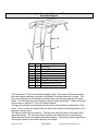
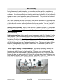
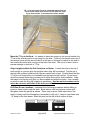
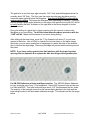
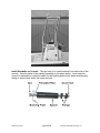
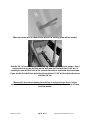
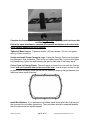
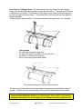
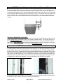
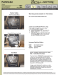
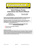
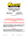
Fishmaster Folding T-Top
Installation Instructions
And Owners Manual
Fishmaster, Inc.
Phone: 877-777-Tower or 678-679-1462
Fax: 877-437-6210
www.Fishmaster.com
[email protected]
Reference 21Sept09
THANK YOU FOR YOUR BUSINESS. IF YOU ARE NOT COMPLETELY SATISFIED
IN ANY WAY WITH YOUR NEW FISHMASTER T-TOP, PLEASE CONTACT US
IMMEDIATELY. Our entire purpose as a company is to create great products at
affordable prices that fishermen love.
IMPORTANT
Please take a few minutes to read the entire installation instructions and become
familiar with the Fishmaster parts and installation before beginning to ensure a
high quality, trouble free installation. We put a lot of effort into our manuals and
are continually improving them so your feedback and suggestions are sincerely
appreciated. If you have any questions during your installation give us a call at
877-777-Tower or e-mail [email protected]
Reference 12Jul06
Pg 1 of 14
Copyright 2005-2006, Fishmaster, Inc.
IMPORTANT NOTES ON INSTALLING AND USING
YOUR NEW FISHMASTER T-TOP
•
Read the entire instruction manual before beginning.
•
If your console has a side door you may need to replace the hinge with
slide in pins described later in this manual.
•
Always apply a thin film of grease to threads before installing to ease
installation. Many people use TEF-GEL which will reduce corrosion on
aluminum and stainless fasteners.
•
Note you are installing from the Bases up. First install the bases, then the
standoffs and then the top canopy frame.
•
Re-torque all hardware after each of the first few uses and then check
regularly.
•
The Fishmaster T-Top is silent by design, if you hear any rattling or noise
at all, then check all hardware for tightness. Call us at 877-777-Tower if
you continue to hear any rattling or noise before using the T-Top as this
means something is not installed correctly.
•
Begin by ensuring you have a protected surface to assemble the parts of
the T-Top so they will not be damaged. The packaging bubble wrap and
cardboard works great, just spread out to create a protected work area.
Grass and carpeted areas are additional options.
•
Always drill in reverse in fiberglass, and only 1” deep to make sure you do
not drill into tanks or cables.
•
Read the entire instruction manual before beginning for a fast, trouble free
installation.
•
Call us at 877-777-Tower or email us at [email protected] if you
have any questions or concerns during the installation.
•
Send us a picture of your boat after installing your T-Top and we’ll send
you a free Fishmaster T-Shirt. Remember to include your shirt size and
mailing address. Please email your pictures to us at
[email protected].
Reference 12Jul06
Pg 2 of 14
Copyright 2005-2006, Fishmaster, Inc.
Getting to Know your Fishmaster T-Top
Assembly Diagram
4
3
7
2
1
6
5
Part
1
2
3
4
5
6
7
8
9
Qty
2
2
4
4
4
2
2
1
1
Description
Lower Leg
Upper Leg
Canopy Frame Sections
Upper Leg Clamps
Bases
Leg Hinge
Canopy Frame Hinge
Sunbrella® Cover (not shown)
Cover Lacing Rope (not shown)
The Fishmaster T-Top is an innovative design in the T-Top market that uses common
parts and design elements that make it affordable, functional and easy to install. The
two main components of the design as shown above are the side legs and the upper
frame. The side legs are mirror images to provide right and left legs. These are hinged
in the center to allow the T-Top to be folded forward.
The legs are typically mounted with the bolt heads to the outside for folding the T-Top
down. They can also be installed with the bolts to the inside if the folding feature is not
required or rarely used.
The canopy frame has four sections. The two front sections attach to the legs by the
upper leg clamps. The two rear sections attach to the front sections at the canopy
frame hinge as shown in the above assembly drawing. The canopy frame hinge allows
the canopy frame to fold in either direction for storage.
Reference 12Jul06
Pg 3 of 14
Copyright 2005-2006, Fishmaster, Inc.
You now know the main components and the terminology of the Parts List used
throughout this document. Note that Parts refer to components of the T-Top and
Items refer to hardware, tools and accessories.
Familiarize yourself with the below hardware items that will be used in the installation.
Fishmaster T-Top Hardware List
Item
1
2
3
4
5
6
7
8
Metric Dimension
M6 x 25 Socket Head Cap Screw
M10 x 35 Socket Head Cap Screw
M10 x 20 Socket Head Cap Screw
#14 x 1-1/2” Sheet Metal Screws
#14 x 1” Sheet Metal Screws
M5 Head Allen Wrench
M8 Head Allen Wrench
Standoff Assembly (shown on Pg. 9)
Application
Attach Sides to Top
All Connectors and Top Hinge
Side Hinge
Connect Front Bases to Boat Deck
Connect Rear Bases to Boat Deck
Supplied tool for M6 Cap Screws
Supplied tool for M10 Cap Screws
Attach Sides to Center Console
Qty
16
24
2
8
8
1
1
2
The above hardware and tools are included with your Fishmaster T-Top and are
referenced to in the installation of the tower by their item number. The following are
items the customer supplies to complete the installation.
Items and tools needed for Installation
The following items will be needed for the installation of the T-Top and are not
supplied.
Customer Supplied Tools
Reversible Drill
11/64” and 3/8” Drill Bits (A 3/8” x 12” wall bit is recommended for standoff installation)
Phillips head screwdriver or drill with Phillips bit
Masking Tape, Tape Measure & Pencil
Level to make sure the boat and parts are square and level during installation
Friend to help hold & hand things
Safety Glasses (always use when drilling fiberglass or metal)
Vacuum for drill shavings from mounting bases and standoffs
Rubber mallet is recommend for adjusting leg width
Center Punch is recommended to start all holes before drilling
Customer Supplied Materials
For Roplene™ boats like Triumph use “Sudbury Elastomeric Sealant” by Rule, available at your
local Triumph dealer or many retailers and online stores
White Lithium or similar marine grease for rotating points and bolts
Non-Permanent Loctite for side hinge bolt and standoffs.
12 Zip Ties or pieces of twine/rope 10” or longer for centering Cover on Canopy Frame
Reference 12Jul06
Pg 4 of 14
Copyright 2005-2006, Fishmaster, Inc.
Main Assembly
During the assembly and installation, you should protect the parts from scratches by
doing the assembly on a tarp, blanket, grass, carpet or the packaging bubble wrap and
cardboard. It is recommended to put masking or trim tape on the floor of the boat and in
a generous area around where the bases will be mounted. This protects the boat and
provides a surface to mark during installation.
Use a level to ensure the beam of the boat is level during installation. It is not important
that the boat be level front to back, only side to side needs to be level. Lift the lower side
of the trailer with wood or similar shims under the tires as needed. You can “eye-ball” it
but it is easier to use a level to confirm the boat and uprights are square and level.
Canopy Frame Assembly: Apply a small amount of grease to sixteen (16) of the Item
2 bolts. Assemble the front two sections and rear two sections first then bolt the front
and rear sections together. Apply a very thin film of grease to the mating hinges on each
side of the canopy.
Side Leg Assemblies: Apply a small amount of grease to eight (8) of the Item 2 bolts.
Install the Item 3 bolts into the side hinges with Loctite leaving the bolt out one turn to
allow for hinge clearance. Assemble the upper and lower legs together for each side.
First, attach the bolts to the front hinges. Apply a very thin film of grease between the
mating surfaces of the side hinge. Next, put the bolts in the rear section of the legs. You
will find that the rear legs are off set approximately 1 inch. This is to put tension on the
bolts not allowing them to come loose or make noise. You will need to push the two
sections together and put in the bolt.
Attach Legs to Canopy at Estimated Width: This can be most easily done on the
ground and will require four people to move the T-Top into the boat. Measure the
approximate width of where you will install the T-Top over your center console. This
does not need to be exact and will be adjusted when you move the T-Top to the boat.
Be sure the legs are wide enough to fit around the console when placed in the boat as
shown below. GREASE AND LIGHTLY SNUG THE ITEM 1 BOLTS AT THIS STEP AS
THEY WILL BE REMOVED LATER TO COMPLETE THE INSTALLATION.
Reference 12Jul06
Pg 5 of 14
Copyright 2005-2006, Fishmaster, Inc.
TIP: Once the Canopy Frame is assembled attached one leg
first as shown below, then stand it up and attach the other
leg as shown below. A second person will be needed.
Move the T-Top to the Boat: It is easiest to have two people on the ground transfer the
T-Top in the vertical position to two people in the boat. With only two people one can lift
the canopy frame and the second can lift at the base of the legs to transfer to the boat in
the horizontal position with one leg on the side of the boat. The key is to take it slow to
prevent damage to the boat or T-Top.
Align Uprights to Mark the Drill Locations on Bases: Loosen the bolts at the top of
each upright so you can align the uprights where they will be installed. Tap the top of
the legs with a rubber mallet so both legs are vertical with a level. Double check that the
T-Top is in its final position for installation and the legs are both vertical. Do not worry
about the canopy frame being centered as it will be removed for final installation. Keep
the bases from moving until after you have marked and drilled the holes. Use a marker
or pencil to mark the four drill locations in each base. Use the marks to make sure the
bases do not move until after all the holes are drilled.
Drill Base Screw Locations: Understand the following procedures before drilling to
ensure a clean hole through the deck. Boats have a very hard gelcoat surface with
fiberglass under the gelcoat as shown. There may be wood, fresh water tanks, fuel
tanks or wiring under the fiberglass so remember to drill only 1” deep for rear bases and
1.5” deep for the front bases. Mark this point on the drill bit with a piece of tape.
Gelcoat
Reference 12Jul06
Pg 6 of 14
Copyright 2005-2006, Fishmaster, Inc.
The gelcoat is a very thin layer approximately 1/16th” thick and the fiberglass below it is
normally about 3/8” thick. The floor near the center console may also have wood or
composite sheet material below the fiberglass. You should ALWAYS run the drill in
reverse while drilling. This keeps the fiberglass from splintering or cracking. Finish the
hole by putting a slight angle (chamfer) on the edge of the gelcoat turning the 3/8” drill bit
by hand (without the drill) as shown on the right side in the above diagram to further
protect the boat.
During the drilling is a great time to have someone with the vacuum to remove the
fiberglass as you are drilling. To drill the holes follow the above procedure with the
11/64” drill bit. Make sure the bases do not move during drilling.
After drilling all the base holes, move the T-Top forward or aft about 6” so you have
access to the holes. Use a 3/8”bit to chamfer the hole as shown in the below image.
Optionally, you can use a small piece of sand paper to radius the edge of the chamfer
also to remove the slight edge. Removing this edge will prevent stress cracking around
the holes.
NOTE: If you have a side console door that interferes with the lower leg when
opening refer to Appendix B to replace the side door hinge with alignment pins.
Put 3M 5200 Adhesive in Holes and Base Location: The 3M 5200 Marine Adhesive
is a key structural part of any T-Top installation. Squirt 5200 into each hole and be sure
it is filled with 5200. Then add a smooth layer about 1/16” thick between the four holes.
The majority of the strength comes from the screws being bonded to the hole and the
base being bonded to the deck adds additional strength. This should look like the image
below.
Reference 12Jul06
Pg 7 of 14
Copyright 2005-2006, Fishmaster, Inc.
Return Bases of T-Top to Hole Locations and PARTIALLY screw in the Items 4 & 5
Sheet Metal Screws: It is easiest to have one person on each side lift the T-Top into
position and slowly lower it to the base locations while you first install one screw into
each base. Once one screw is in each base screw the rest of the screws in but
leave each screw out ¼” as shown below until the standoffs are installed. It takes
hours for the 5200 to begin to cure so don’t worry about the screws becoming bonded
into the holes. Wipe up any excess 5200.
Remove the Frame Canopy to Complete the Standoff Installation: Once the bases
are partially screwed into the deck of the boat remove the Four (4) upper leg clamps and
the Canopy Frame as shown below. The reason for this is moving the clamps on the top
section frame during alignment will scratch the finish of the aluminum. This also allows
the legs to be more accurately aligned vertically.
Reference 12Jul06
Pg 8 of 14
Copyright 2005-2006, Fishmaster, Inc.
Install Standoffs on Console: The next step is to install a standoff on either side of the
console. Note the parts of the standoff assembly in the photo below. Look under the
console to determine a location suitable for the backing plate shown below avoiding any
wiring or obstructions under the center console.
Reference 12Jul06
Pg 9 of 14
Copyright 2005-2006, Fishmaster, Inc.
Make sure there are no obstructions where the backing plate will be located.
Use the 3/8” bit to drill through the T-Top leg and center console as shown. Use a
center punch to locate the hole on the tube and drill first with the 11/64” bit. If
needed you can drill the hole in the console from above and below the cross tube.
If you do this first drill from both directions with the 11/64” bit then both directions
with the 3/8” bit.
Measure for the spacer making sure the leg is vertical using a level. Cut the
spacer to fit and remember it’s easier to cut or sand a little more material off then
to add a washer.
Reference 12Jul06
Pg 10 of 14
Copyright 2005-2006, Fishmaster, Inc.
Complete the first standoff installation using Loctite tightening both the Acorn Nut
and Backing Plate Nut.
Follow the same directions to complete the standoff installation on the other side
of the console ensuring the leg is vertical.
Tighten all Base Screws: Tighten all sixteen (16) base screws. Do not over tighten
and if you hear noise stop.
Center and Install Frame Canopy to Legs: Center the Canopy Frame over the Upper
Leg Clamps for final installation. Start but do not tighten each Item 1 bolt into the Upper
Leg Clamps then tighten the bolts keeping the gap on each side of the clamp equal.
Center Cover to Canopy Frame: The next step is to center the cover onto the Canopy
Frame with the Sunbrella label to the rear of the boat. Use tie wraps, zip ties or rope
on each corner as shown below, as well as one each side keeping the gap between the
fabric and frame equal all around.
Install Rod Holders: If you purchased rod holders install them before the final lacing of
the cover per the rod holder instructions. The rod holders should be centered between
the cover grommets and equally spaced.
Reference 12Jul06
Pg 11 of 14
Copyright 2005-2006, Fishmaster, Inc.
Lace Cover to Canopy Frame: The next step is to lace the cover onto the Canopy
Frame. We recommend starting in the center at the front of the T-Top and tie off the rope
to the frame or as shown. Then lace half of the fabric to the center in the back snug but
not tight enough to move the fabric. The second half of the lacing will be done tighter to
tension the fabric.
There should be approximately ½ inch space between canvas and rail once complete.
-
Lacing Steps
Go top down through the grommet
Go under the edge of the fabric but over the tube
Go bottom up through the grommet
Move to the next grommet and repeat
The complete lacing will look the same as above.
You can now go back pulling the lacing between the grommets and tighten the fabric if
needed. After the first few uses the fabric will need to be retightened by this method.
Remember to send us a few pictures of your boat with the Fishmaster T-Top
installed AND YOUR SHIRT SIZE for a free Fishmaster T-Top T-Shirt. International
customers will need to cover the shipping cost. We also sincerely appreciate any
Reference 12Jul06
Pg 12 of 14
Copyright 2005-2006, Fishmaster, Inc.
feedback on our products, manuals, website or any other customer
recommendations
Using your Fishmaster T-Top – Operating Instructions
The Fishmaster T-Top folds down for storage. It is no problem to trailer with the T-Top up. If you fold the
T-Top down for trailering make sure to tie it down well so the wind can not move it. To fold the tower
down remove two bolts at each corner of the legs and fold the T-Top forward. If the T-Top rests on
fiberglass, use a vest or other cushion to protect the boat and T-Top. If you need to also fold the Frame
Canopy remove the two outside bolts on each side leaving the center bolt in as a hinge point.
•
Remember to protect your boat and T-Top when the tower is folded down. We recommend using
a koozie, vest or other padding between any locations where the T-Top touches your boat to
protect each item.
•
When towing your boat the Fishmaster T-Top can be in the up or folded position. If you tow with
the T-Top up, note the height of the T-Top and make sure you have overhead clearance. If you
tow with the T-Top down make sure you have pads where the tower touches the boat and the TTop is securely tied into place.
•
The Fishmaster T-Top is stiff and silent by design. If you hear any rattling or noise from the TTop check all hardware for tightness. Call us at 877-777-Tower if this does not correct the
problem.
- Always understand and follow the warnings on the T-Top warning label
Fishmaster T-Top, Inc. - 5 Year Warranty - Fishmaster T-Top warrants that for a period of 5 years from the date the T-Top is sold
at retail, that Fishmaster T-Top will repair directly, or supply parts for the repair of any material cracks, fractures or structural failures
that are a result of a manufacturing defect. Anodizing and powder coated surfaces as well as all hardware corrosion are specifically
excluded as their care and use cannot be controlled by Fishmaster. Any modifications or improper use, not approved in writing by
Fishmaster, shall void this warranty. Fishmaster is not responsible for personal injury or damage to the boat caused by the use of
this T-Top. Fishmaster’s obligation under this warranty shall not include any transportation charges or costs of installation or any
liability for direct, indirect or consequential damages resulting from delay or improper installation of the T-Top. Instead of reading all
this fine print, get your T-Top on the boat and go fishing! No dealer, retailer or manufacturer is the agent of Fishmaster and may not
assume for Fishmaster any liability in connection with this warranty. This warranty is in lieu of all other warranties, expressed or
implied, including any warranty of merchantability or of fitness for a particular purpose. If you need to make a warranty claim contact
Fishmaster at 877-777-Tower to receive a return authorization number which is required for all claims. Defects must be reported
within 30 days of receipt.
We provide a 30 day - No Questions Asked "Love it or Return it" Money Back guarantee. Simply ship it
back with a note on why you are returning it and we will refund your money, less our cost to ship the
product to you.
Reference 12Jul06
Pg 13 of 14
Copyright 2005-2006, Fishmaster, Inc.
APPENDIX A -
Wiring Instructions for your Fishmaster T-Top
If you add speakers, lights, antenna or other items to your Fishmaster T-Top, you can hide the wires
inside of the tubing of the T-Top. When wiring and you get to the hinge’s drill a hole 1 inch above the weld
on the top section and drill a hole 1” below the weld on the bottom section. Loop the wire out of the tubing
of one section and back into the tubing in the other section. Leave 5 – 6 inches of wire out in order for the
t-top to fold. The hole size will depend on what size wire and connector you are running and how many
items you need to wire. The maximum hole size we recommend is ½” but normally smaller is all that is
needed.
1”
½”
ADDITIONAL RESOURCES OF INTEREST
The various connectors, finishing grommets and items you will need for wiring lights and speakers can be
found at Radio Shack, Home Depot, Lowe’s, Ace and other hardware stores. You can also find much of
this at www.WayTekWire.com as well as many other online sources. There are some great technical
documents at www.installdr.com that may be of assistance as well. If you are interested in making your
own speakers or other items for your T-Top, check out www.diyTower.com.
APPENDIX B -
Side Door Hinge Replacement
For boats with side console doors that interfere with the lower leg, you will need to replace the hinge with
pins to slide the door in and out of locked position. Remove the door by removing the screws that hold
the hinge to the console. Replace two to three screws with stainless dowel pins (available at Ace, Home
Depot, Lowes, etc) that are about the same diameter as the screws. You may need a drill the same size
as the dowel, normally both will be 1/8” or 3/16” diameter. Drill into the door and secure the dowel about
half way in with a very small amount of 5200. Drill the console at the mating position and open the hole
up slightly with the drill for easy clearance. You can now slide the door into and out of position.
This has worked great for all the boats we have encountered. If you have a different type hinge or door
style, please contact us for assistance. If you could email us pictures we will be happy to help determine
the best way to make it easy to remove and replace your console door.
Reference 12Jul06
Pg 14 of 14
Copyright 2005-2006, Fishmaster, Inc.