1
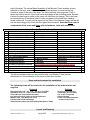
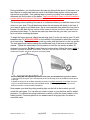
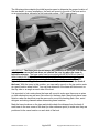
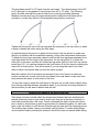
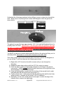
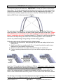
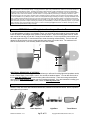
Installation Instructions
And Owners Manual
MTE
Monster Tower, Inc.
1704 Henry G. Lane Street
Maryville, TN 37801
Phone: 877-77-Tower
Fax: 877-232-6538
www.MonsterTower.com
[email protected]
Reference 18Nov2008 – V14
It is critical to lubricate bolt threads with included Anti-Seize
before installing Nylock Nuts to prevent the precision stainless steel
hardware from galling and locking, even if you are test-fitting parts together
before installation.
Leave Legs and Top Section protected with bubble wrap sleeves, removing
only the ends as needed, to protect the boat and tower during installation.
THANK YOU FOR YOUR BUSINESS. IF YOU ARE NOT COMPLETELY SATISFIED
IN ANY WAY WITH YOUR NEW MONSTER TOWER, PLEASE CONTACT US
IMMEDIATELY. Our entire purpose as a company is to create great products at
affordable prices that our customers love.
IMPORTANT
Please take a few minutes to read the installation instructions and become
familiar with the MTE parts and installation before beginning to ensure a high
quality, trouble free installation. If you have any questions during your
installation give us a call at 877-77-Tower or e-mail [email protected]
Reference 18Nov08 – V14
Pg 1 of 12
Copyright 2002-2008, Monster Tower, Inc.
IMPORTANT NOTES ON INSTALLING AND USING
YOUR NEW MONSTER TOWER
Read the entire instruction manual before beginning
Always apply a thin film of Anti-Seize to Threads before putting a nut on or
the hardware can lock up. This is normal for Stainless Steel hardware and
the Anti-Seize eliminates the problem.
Do not use nut drivers to run bolts. Always turn by hand to prevent the
bolts from heating up.
Strengthen the mounting areas of the bases if the fiberglass is less than
3/8” thick.
Torque M12 Nylock Nuts to 65 ft-lbs and M12 x 35 Bolt to 30 ft-lbs, and the
M10 x 40 Nylock Nuts to 50 ft-lbs.
Re-torque all hardware (especially M12 and M10 Nylock nuts) after each of
the first few uses and then check regularly.
Note that after drilling the holes in the mating swivel, the tower is
permanently set to that rear leg mounting width and can not be moved to
another boat or area unless it has the same rear leg mounting width.
The tower is silent by design. If you hear any rattling or noise check all
hardware for tightness, especially the Heim joint jam nuts and set screws
in the rear swivel collar. Call us at 877-77-Tower if you continue to hear any
rattling or noise before using the tower as this means something is not
installed correctly.
Leave protective bubble wrap sleeves on the legs and top section until the
drilling steps on page 10. This will protect your boat and the tower during
installation. Only remove the areas needed for installation.
Visit the support information at www.MonsterTower.com for additional
information including details on customer installations.
Call us at 877-77-Tower if you have any questions or concerns during the
installation.
Reference 18Nov08 – V14
Pg 2 of 12
Copyright 2002-2008, Monster Tower, Inc.
Getting to Know your MTE
Parts & Assembly Diagrams
The MTE is an innovative design in the Wakeboard Tower market that uses many
common parts and design elements that make it affordable and easy to install. There
are three main components of the design as shown in the Assembly Diagram: front
legs, rear legs and the top section. The front legs are identical and there are right and
left rear legs. One rear leg and the mating part of the top section are marked with blue
dots where the two parts mate.
The Top Section Assembly shows how the fixed leg swivel at the top of each of the legs
mate to swivels on the top section. These swivels allow the front or rear legs to move
closer together or farther apart to adjust to different boat widths. The rear swivels on the
top section can also rotate in the rear swivel collar allowing the front and rear legs to
move closer together or farther apart to adjust to different mounting locations on the
Reference 18Nov08 – V14
Pg 3 of 12
Copyright 2002-2008, Monster Tower, Inc.
side of the boat. The unique Base Assembly of the Monster Tower includes: a base
fastened to the boat, and a base swivel that allows the base to mount on the top,
outside or angle of the side of the boat. The Heim joint has three purposes. First, it
allows the base to mount if your boat has a slight angle at the mounting areas. Second,
it allows the rear legs to rotate so the tower can fold down for storage. Third, the Heim
joint prevents any of the lateral (side to side) movement of the tower from causing
stress to the boat. You are now an expert on the Parts of the Monster Tower and we will
use the terminology of the Parts List throughout this document. Note that Parts refer to
components of the tower and Items refer to hardware, tools and accessories.
Monster Tower Hardware List
Item Metric Dimension
1
2
3
4
5
6
7
8
9
10
11
12
13
14
15
16
Equivalent
Connection
Qty
Inch Dimensions
M8 x 50 SHCS / Washer / Nylock
5/16-18 x 2"
Base to boat
8
M12 x 85 SHCS / Washer / Nylock
1/2-13 x 3-1/2"
Base to base swivel
4
M12 x 35 SHCS
1/2-13 x 1-3/8"
Attach rod end to base swivel
4
M12 Rod End Bearings (Heim Joint) 1/2" Rod End Bearing
Base swivel to rod end support
4
M12 Flat Hex Nut
1/2" Hex Jam Nut
Jam nut for rod end
4
M12 x 75 SHCS / Washers / Nylock
1/2" x 3"
Front Leg swivels to top section 2
M12 x 12 Set Screw (preinstalled)
3/8" x 1/2"
Lock rear swivel in collar
4
3" x 2" Metal Backing Plate
3" x 2"
Backing plate for under deck
4
Monster Paw Backing Pads
3" x 2"
Pads to boat mounts
8
#14 O-Rings (3/4”ID x 15/16”OD)
(optional after install)
Align rod ends to base swivel
4
2-1/2” Teflon Fender Washer
Front Legs & Top Section Swivel 2
M5 Head Allen Wrench
For M10 Set Screws
Supplied tool
1
M6 Head Allen Wrench
For M8 Bolts
Supplied tool
1
M10 Head Allen Wrench
For M12 Bolts
Supplied tool
1
Foil Packet of Anti-Seize Lubricant This is critical to use on all bolt threads to prevent galling.
6
M10x40 SHCS / Washers / Nylock
3/8” x 1-1/2”
Rear Leg to top section
SHCS - Socket Head Cap Screw (Bolt)
Nylock - Nut with built in locking ring
The above hardware and tools are included with your Monster Tower and are
referenced to in the installation of the tower by their item number.
Items and tools needed for Installation
The following items will be needed for the installation of the tower and are not
supplied.
Required
Optional
Reversible Drill & 1/8”, 1/4”, 5/16”, 3/8” & 1/2" Drill Bits
Adjustable wrench or 13mm & 19mm metric sockets
Torque Wrench (no pneumatic wrenchs)
Any general purpose grease for Front Leg Swivels
Masking Tape, Tape Measure & Pencil
Friend to help hold & hand things
Safety Glasses (always use when drilling fiberglass or metal)
Vacuum for drill shavings
Throw tarps (to cover boat)
1/4” or 3/8” PT Plywood
Silicone Sealant
Loctite removable threadlock
(In place of anti-seize)
Layout and Planning
Reference 18Nov08 – V14
Pg 4 of 12
Copyright 2002-2008, Monster Tower, Inc.
During installation, you should protect the tower by doing all the layout of the tower on a
tarp, blanket or carpet and leave as much of the bubble wrap sleeves on the legs and
top section as possible. Use masking tape to protect your deck from scratches as you
determine the final location of the bases. Apply included Anti-Seize to all bolt threads to
prevent galling and locking of the precision stainless steel hardware.
The first step when installing the tower is to understand where you want the tower to fold
down to in your boat. This will determine where the rear bases will attach to the boat. If
your tower is going to be folded down, this is more important than where the tow point is
located. You will want the top section of the tower to rest on your floor, rear seat or sun
pad when folded down. To ensure the tower lays down the way you want, you need to
lay it out before installing the bases.
To begin the layout process, attach the rear legs (part 5) to the top section (part 13) with
hardware Item 16 WITH ANTI-SEIZE on the outside of the threads to attach the rear legs
as shown below. The blue dot on one rear leg mates with the blue dot on the top section.
The rear legs should radius towards the outside and front of the boat as shown in this
manual. Tighten the setscrews in the top section to hold the top section at about 30
degrees from vertical. Do Not Loosen these set screws when folding the tower. NOTE – If
you plan to purchase the Monster Tower Bimini, it mounts to the rear legs of the tower. If the tower is
mounted too far back, the driver will not be covered by shade.
Before moving the rear legs and top section to the boat, pre-assemble the leg ends as shown:
1) Confirm Heim joints (part 7) are screwed into the end of each leg as far as possible as shown above
to the right.
2) Attach the Heim joint to the Base Assembly as shown in the Base Assembly view. Make sure the oring is on the bolt between the Heim joint and Base Swivel. (The o-ring aligns the Heim joint to the
base swivel and is not required after installation).
Now prepare your boat by putting masking tape on the hull in the locations you will
mount the rear bases. You can also put towels or tarps on your deck as well for added
protection. Try different mounting locations to confirm you like the tower location in the
folded position. Customer photos at our website can be a big help also for where to
mount the tower.
Reference 18Nov08 – V14
Pg 5 of 12
Copyright 2002-2008, Monster Tower, Inc.
The following picture depicts the initial layout process to determine the proper location of
the rear bases. In many installations, the base will mount to the side of the boat and or
on a curved surface, instead of a flat horizontal surface. (MT1 tower shown)
IMPORTANT: The Heim joint should always be positioned to the back of the base
as shown to ensure the base does not contact the rear leg when the tower is
folded for storage. The base swivel can be mounted with the M12x35 bolt (item 3)
either towards the inside of the boat or on the outside. For easiest access we
recommend mounting the base swivel with the bolt towards the outside. The M12
Nylock Nut connecting the base and base swivel should be towards the front of
the boat. With the tower in this position, you can easily move it so the top section rests
at a good location when folded. You can now determine if the base will best mount on
the top, side or an angle on each side of the boat.
It is important to look under where the base will mount to make sure there are no wires
or other obstructions as well as a flat surface for the base plate. Many boats have foam
flotation under the deck that must be removed to mount the backing plate. Also, avoid
stringers and wiring channels when determining base locations.
Mark the base locations on the tape and double check the distance from the back of
each base to the rear corner of the boat (or other reference point) to make sure they are
positioned in the same location on each side of the boat.
Reference 18Nov08 – V14
Pg 6 of 12
Copyright 2002-2008, Monster Tower, Inc.
The front bases are 48” to 75” apart from the rear bases. The optimal range is from 53”
to 65” although it is acceptable to mount them from 48” to 75” apart. The following
shows the side view with the tower at ideal front to rear leg-mounting distances.
Measure from the rear leg to the approximate location where the front base will be
mounted to confirm they will be in the acceptable range before continuing.
Tighten the bolts at the top of the rear legs and the setscrews in the top section to make
it easier to handle the tower during the final steps.
An optional step at this point is to attach the front legs to the top section to make sure
they do not interfere with the windshield opening, or any other unforeseen obstructions.
To attach the front legs, assemble a base to each of the front legs (base assembly front
view) and attach the front legs to the top section. Do this using Part 15 to attach the
Heim joint to the base, and Item 6 to attach the leg swivel (part 8) to the front top section
swivel (part 12). You can then determine the final location of all four bases by placing the
tower into its final position. This will be easier if you can hang the tower from a tree,
rafter or have a few friends help you hold the tower in place.
Mark the location of the front bases and measure from a front base to a reference
location on the boat, as well as from the front base to the rear base to make sure they
are positioned the same on both sides of the boat.
You are now ready to attach the rear bases to the boat, so you will need to detach them
from the legs and take the base assemblies apart. If you have the front legs attached to
the top section you will want to detach them as well.
Attaching the bases to the deck of the boat
Take a few minutes to double check the dimensions between the base locations and
several reference points on your boat to make sure they are in the same locations on
each side (measure twice, drill once). Check underneath the deck to make sure there
are no wires or obstructions as well as good places for the backing plate. For each rear
base, mark the location to drill the two holes through the deck as in the following picture.
The masking tape makes it easy to accurately mark the holes. To make drilling easier
we recommend center punching the marks so the drill bit does not wander when drilling.
Reference 18Nov08 – V14
Pg 7 of 12
Copyright 2002-2008, Monster Tower, Inc.
Understand the following procedures before drilling to ensure a clean hole through the
deck. Boats have a very hard gelcoat surface with fiberglass under the gelcoat as
shown below.
Gelcoat
The gelcoat is a very thin layer approximately 1/16th” thick and the fiberglass below it is
normally about 3/8” thick. IMPORTANT: If the fiberglass below the gelcoat is less than
3/8” thick, you need to add fiberglass cloth and/or marine treated plywood to build up
the largest available area to at least 3/8” thick. You need to check all mounting points as
the fiberglass thickness may vary on the boat.
You MUST run the drill in reverse while drilling the holes or the gelcoat will chip, as it is
extremely brittle. Remember to run the drill in reverse for the entire hole.
This is also a great time to have someone with a vacuum to remove the fiberglass as
you are drilling. To drill the holes use the following procedures:
1) Begin with a 1/8” bit and run the drill in reverse until you are through the
fiberglass.
2) Repeat the same step as above with the 5/16” bit running in reverse.
3) Finish the hole by putting a slight angle (chamfer) on the edge of the gelcoat
turning the ½” drill bit by hand (without the drill) as shown on the right side in the
above diagram to further protect the boat.
4) Using the backing plate, double check the location of the second hole for each
base and then drill the second hole using steps 1-3.
5) Confirm the two Item 1 bolts will go through the backing plate and the two holes
without binding. If needed, drill the holes to 3/8” for clearance.
6) Optionally, you can use a small piece of sand paper to radius the edge of the
chamfer also to remove the slight edge..
Reference 18Nov08 – V14
Pg 8 of 12
Copyright 2002-2008, Monster Tower, Inc.
Next, install the rear bases (part 2), Monster Paws (part 16) -hollow sections towards
the boat, and backing plate with Item 1 hardware as shown below. If you are reinforcing
the underside of your deck, the wood will go between the deck and the Monster Paw
under the deck of the boat. Remember to apply Anti-Seize to the entire length of the M8
bolts. Tighten these by hand; do not use a drill or driver. There is not a specific torque
specification since each boat is different. Tighten until you begin to see the Paw being
compressed. Check the base to make sure it is tight and if needed turn another ¼ turn.
Repeat until the base is rigid. Note: You can optionally add non-adhesive caulk / sealant
between the top of the boat and the Monster Paw to ensure a waterproof seal.
Rebuild the base assembly onto the mounted base as you previously had it for the initial
setup (Base Assembly View).
Attach the rear legs and top section setup to the rear bases with Item 3 (M12 x 35 bolt).
Base
Rubber Base Pads
Boat Deck
Front of Boat
Backing Plate
The next step is to determine the final location of the front mounts.
Attach the front leg swivels (part 8) to the front swivels (part 12) using Item 6 of the
hardware list. Include the Item 11 Teflon washers between the mating swivels of the
front legs if you would like to, but they are not required if your tower will not be folded
down. It is also recommended to place a small film of grease on both sides of the
stainless washers so the bolt will not tighten and loosen when the front legs are rotated
in. If your tower stays up all the time do not use grease or the Teflon washer and torque
to 70 ft-lbs. If you will be folding your tower down torque the bolt to 20-30 ft-lbs.
Rotate the tower into the up position and move the front legs around to determine the
desired location of the front bases. You may have already done this during the optional
setup on page 7. Double check the location of the front bases,
and then follow the same drilling and installation procedure
used to mount the rear bases to finish the front base installation.
Make sure the bases are facing the correct direction as shown
in the Base Assembly view. Use Item 15 instead of the M12 x
35 bolts used on the rear legs, placing the lanyard washer onto
the M12x85 bolt (Item 2) on the outside of the base as shown
here. The tower installation is almost complete and the last step
provides the final adjustments to ensure a stiff tower that is
custom fit to your boat.
Reference 18Nov08 – V14
Pg 9 of 12
Copyright 2002-2008, Monster Tower, Inc.
IMPORTANT - Final Adjustments and Locking
The last step is to center the tower on the boat and lock everything securely into place
to ensure the tower is stiff and silent. IMPORTANT - Center the Tower on the boat as
shown here. Do this by measuring from the base on one side to the rear swivel on the
other side as shown below. Check both sides until the measurements are within ¼” in
both directions and then tighten the setscrews in the Part 10 Rear Swivel Collar and
tighten all M12 bolts in the top section to 65 ft-lbs.
The next step is to install Item 16 to lock together the Rear Top Section Swivel and
Rear Leg Swivel. This maximizes the side-to-side (lateral) stiffness of the tower. Double
check that the tower is centered as above before drilling. Once holes have been drilled,
there is no adjusting the tower. Use the included 5/16” (8mm) bit to drill through the pilot
hole and all the way through the other side of the mating swivel. Use a vacuum to
remove any metal shavings during drilling and wear safety glasses.
Drilling the mating swivels will be faster using the following steps:
1) Begin with the 10mm drill bit, drilling through the pilot hole and starting the hole in the
mating swivel.
2) Switch your drill bit to a smaller size (3/16” or ¼”) and drill partially through the tower,
making sure to stay centered in the pilot hole.
3) Switch your drill bit back to the 10mm bit and drill through the smaller hole.
4) Continue switching between drill bits until you have drilled completely through the
swivels.
Insert Item 16 through the hole, and tighten to 30 ft-lbs. At this point double check that
the tower is centered before drilling and installing the next bolt. Repeat the anchor bolt
installation on the other rear leg of the tower. Drill and install the second anchor bolt on
each of the mating swivels to complete the installation of the four anchor bolts. The
tower is now centered and locked into position. All four anchor bolts MUST be installed.
The last step is to double check that all fasteners are tight, including the top section set
screws and jam nuts tightened against the leg rod end support The tower is now ready
Reference 18Nov08 – V14
Pg 10 of 12
Copyright 2002-2008, Monster Tower, Inc.
for use. The Monster Tower IS ABSOLUTELY SILENT when installed correctly. Shake
the tower and if you hear any noise check all the hardware and make sure it is tight. If
you hear any noise or rattling at any time, something is wrong, please correct it or call
us before using the tower.
Thank you again for your business and if we can be of assistance in any way please call
us at 877-77-Tower or email us at [email protected]
Remember to send us a few pictures of your boat with the Monster Tower
installed AND YOUR SHIRT SIZE for a free Monster Tower T-Shirt. International
customers will need to cover the shipping cost.
Using your Monster Tower – Operating Instructions
The Monster Tower folds down flat to fit under your boat cover fast and easy. To fold the tower down
remove the Quick Release bolts from the front bases. The Heim joints now allow the tower to pivot
towards the back of the boat. If the tower rests on fiberglass, use a vest or other cushion to protect the
boat and tower. DO NOT loosen the set screws to flatten out the top section. The top section needs to
stay at the same angle folded as when not folded. The front legs are then folded one at a time to the side
for storage. Always use a vest, koozie or other cushion to protect the boat where the leg touches and if
the two front legs touch each other. (MT1 shown below folded)
•
Remember to protect your boat and tower when the tower is folded down. We recommend using
a koozie, ski vest or other padding between any locations where the tower front legs touch each
other, or anywhere the tower touches your boat to protect each item. It is normally a great place
to hang your vest to dry after riding as well.
•
When towing your boat the Monster Tower can be in the up or folded position. If you tow with the
tower up, note the height of the tower and make sure you have overhead clearance. If you tow
with the tower down make sure you have pads where the tower touches the boat or where the
front legs touch to prevent damage.
•
The Monster Tower is stiff and silent by design. If you hear any rattling or noise from the tower;
or see any movement in the tower, then check all hardware for tightness. Call us at 877-77Tower if this does not correct the problem.
-
Reference 18Nov08 – V14
Always understand and follow the warnings on the tower warning label
Pg 11 of 12
Copyright 2002-2008, Monster Tower, Inc.
Monster Tower, Inc. - 5 Year Warranty - Monster Tower warrants that for a period of 5 years from the date the tower is sold at
retail, that Monster Tower will repair directly, or supply parts for the repair of any material cracks, fractures or structural failures that
are a result of a manufacturing defect. Anodizing and powder coated surfaces as well as all hardware corrosion are specifically
excluded as their care and use cannot be controlled by Monster Tower. Any modifications or improper use, not approved in writing
by Monster Tower, shall void this warranty. Monster Tower is not responsible for personal injury or damage to the boat or other
items caused by the use of this tower. Monster Tower’s obligation under this warranty shall not include any transportation charges
or costs of installation or any liability for direct, indirect or consequential damages resulting from delay or improper installation of the
tower. Instead of reading all this fine print, get your tower on the boat and go ride! No dealer, retailer or manufacturer is the agent
of Monster Tower and may not assume for Monster Tower any liability in connection with this warranty. This warranty is in lieu of all
other warranties, expressed or implied, including any warranty of merchantability or of fitness for a particular purpose. If you need to
make a warranty claim contact Monster Tower at 877-77-Tower or email [email protected] before returning any items.
Defects must be reported within 30 days of receipt.
APPENDIX A -
Wiring Instructions for your Monster Tower
If you add speakers or lights to your Monster Tower, you can hide the wires inside of the rear legs of the
tower as well as in the straight cross member of the top section. Since the mating parts insert ½” inside
each end of the rear leg you can drill 1” away from the weld lines. For the top section cross member you
will need to place the hole 3” from the weld line to clear the rotating collar assembly. The hole size will
depend on what size wire you are running and how many items you need to wire. The maximum hole
size we recommend is ½” but normally smaller is all that is needed.
1”
½”
ADDITIONAL RESOURCES OF INTEREST
The various connectors, finishing grommets and items you will need for wiring lights and speakers can be
found at Radio Shack, Home Depot, Lowe’s, Ace and other hardware stores. You can also find much of
this at www.WayTekWire.com as well as many other online sources. There are some great technical
documents at www.installdr.com that may be of assistance as well. If you are interested in making your
own speakers or other items for your tower, check out www.diyTower.com.
Monster Tower Accessories
Monster Tower also offers Quick Release Wakeboard, Waterski and Surfboard Racks: Mirrors, Speakers
and Lights to fit your tower.
Wakeboard Racks
Reference 18Nov08 – V14
Tower Speakers
Pg 12 of 12
Light Bars
Tower Mirrors
Copyright 2002-2008, Monster Tower, Inc.