1
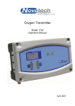
Oxygen Transmitter Model 1732 Operators Manual February 2015 TABLE OF CONTENTS 1. USING THIS MANUAL ................................................................................................................................. 3 1.1 CAUTIONS .................................................................................................................................................. 3 1.2 WARNING SYMBOLS ................................................................................................................................... 4 2. INTRODUCTION ........................................................................................................................................... 5 3. DEVICE SPECIFICATIONS .......................................................................................................................... 7 3.1 HARDWARE SPECIFICATIONS ....................................................................................................................... 7 3.2 OPERATIONAL SPECIFICATIONS ................................................................................................................... 8 3.2.1 SCALING OF ANALOG OUTPUTS CHANNEL #1 AND CHANNEL #2 ............................................................. 8 3.2.2 LOCAL DISPLAY OF PROCESS VARIABLES .............................................................................................. 8 4. DISPLAY AND KEYPAD .............................................................................................................................. 9 4.1 RUN MODE DISPLAY ................................................................................................................................... 9 4.2 OXYGEN DISPLAY ..................................................................................................................................... 10 4.3 KEYPAD ................................................................................................................................................... 11 4.3.1 KEYPAD IN RUN MODE ....................................................................................................................... 11 4.3.2 KEYPAD IN THE SETUP MENU ............................................................................................................. 12 4.3.3 INFORMATION SCREEN ....................................................................................................................... 13 5. SETUP MENU ............................................................................................................................................. 15 5.1 SETUP MENU FUNCTION SUMMARY ........................................................................................................... 15 5.2 SETUP MENU DISPLAY .............................................................................................................................. 15 5.3 SETUP MENU FUNCTIONS ......................................................................................................................... 16 5.3.1 PROBE 1 & PROBE 2 OFFSET ............................................................................................................. 16 5.3.2 LOWER LINE ITEMS ............................................................................................................................ 16 5.3.3 OXYGEN DISPLAY UNITS .................................................................................................................... 17 5.3.4 DAMPING FACTOR .............................................................................................................................. 17 5.3.5 PROCESS ALARMS ............................................................................................................................. 17 6. ALARMS ..................................................................................................................................................... 19 6.1 CHECKING AND ACCEPTING AN ALARM ...................................................................................................... 20 6.1.1 CURRENT ALARMS ............................................................................................................................. 20 6.1.2 ALARM LOG ....................................................................................................................................... 21 6.2 ALARM RELAYS ........................................................................................................................................ 21 6.3 COMMON ALARMS .................................................................................................................................... 22 6.4 SELECTABLE PROCESS ALARMS ................................................................................................................ 23 6.5 WARNING MESSAGES ............................................................................................................................... 23 7. GAS CALIBRATE AND PURGE ................................................................................................................ 25 7.1 ACTIONS THAT OCCUR WHEN THE GAS SOLENOID BUTTONS ARE PRESSED ................................................. 26 8. INDEX .......................................................................................................................................................... 27 February 2015 1732 Oxygen Transmitter Operators Manual 1 Copyright NOVATECH CONTROLS PTY LTD — 2015 This manual describes the transmitter firmware version 1.29, February 2015 Neither the whole nor any part of the information contained in, or the product described in, this manual may be adapted or reproduced in any material form except with the prior written approval of Novatech Controls Pty Ltd (Novatech). The product described in this manual and products for use with it are subject to continuous developments and improvement. All information of a technical nature and particulars of the product and its use (including the information in this manual) are given by Novatech in good faith. However, it is acknowledged that there may be errors or omissions in this manual. A list of details of any amendments or revisions to this manual can be obtained upon request from Novatech Controls Technical Enquiries. Novatech Controls welcome comments and suggestions relating to the product and this manual. All correspondence should be addressed to: Technical Enquiries Novatech Controls Pty Ltd 309 Reserve Road, Cheltenham Victoria 3192 Australia Tel: Fax: Email: Web site: +61 3 9585 2833 +61 3 9585 2844 [email protected] http://www.novatech.com.au/ Novatech Controls or their authorised dealers should carry out all maintenance and service on the product. Novatech Controls can accept no liability whatsoever for any loss or damage caused by service or maintenance by unauthorised personnel. This manual is intended only to assist the reader in the use of the product, and therefore Novatech Controls shall not be liable for any loss or damage whatsoever arising from the use of any information or particulars in, or any error or omission in, this manual, or any incorrect use of the product. Operators Manual 2 February 2015 1732 Oxygen Transmitter 1. USING THIS MANUAL This manual is a shortened version of the 1732 Oxygen Transmitter product manual to be used by the operator. It does not cover the commissioning, calibration or servicing of the 1732 Oxygen Transmitter. If more detailed information is required than what is provided in this manual please refer to the more detailed 1732 Oxygen Transmitter Technical Manual. Both manuals are supplied with each transmitter and are also available to download at the Novatech Controls website. http://www.novatech.com.au/1732 It is assumed in this manual that the transmitter has been installed by qualified personal and that the wiring to the main power supply, the oxygen probe and all the associated signal devices complies with the local safety codes and regulations. 1.1 Cautions Please read the safety information below before connecting power to the transmitter. CAUTION 1 The probe heater is supplied with MAINS VOLTAGE. This supply has electrical shock danger to maintenance personnel. Always isolate the transmitter before working with the probe. The EARTH wire (green) from a heated probe must ALWAYS be connected to earth. CAUTION 2 Combustion or atmosphere control systems can be dangerous. Burners must be mechanically set up so that in the worst case of equipment failure, the system cannot generate explosive atmospheres. This danger is normally avoided with flue gas trim systems by adjustment so that in the case of failure the appliance will not generate CO in excess of 400 ppm in the flue. The CO level in the flue should be measured with a separate CO instrument, normally an infrared or fuel cell type. CAUTION 3 The oxygen probe is heated to over 700°C/1290°F and is a source of ignition. Since raw fuel leaks can occur during burner shutdown, the transmitter has an interlocking relay that removes power from the probe heater when the main fuel shut-off valve power is off. If this configuration does not suit or if it is possible for raw fuel to come into contact with a hot oxygen probe then the Model 1732 transmitter with a heated probe will not be safe in your application. An unheated probe can be utilised in such applications, however the oxygen readings are valid only above 650°C/1200°F. CAUTION 4 The reducing oxygen signal from the transmitter and the associated alarm relay can be used as an explosive warning or trip. This measurement assumes complete combustion. If incomplete combustion is possible then this signal will read less reducing and should not be used as an alarm or trip. A true excess combustibles analyser, normally incorporating a catalyst or thermal conductivity bridge, would be more appropriate where incomplete combustion is possible. Also read the probe electrical shock caution in the probe heater interlock caution in chapter 4.7 of the Model 1732 Technical Manual. CAUTION 5 FIL-3 filter. If the optional FIL-3 has been fitted to the 1231 probe in this installation, please read the Important Notice in the Technical Manual. February 2015 1732 Oxygen Transmitter Operators Manual 3 1.2 Warning Symbols Danger, high voltage. Risk of electrical shock. Caution hot surface. Caution, risk of danger. See additional information in the manual. Operators Manual 4 February 2015 1732 Oxygen Transmitter 2. INTRODUCTION The Novatech 1732 Dual Probe Oxygen Transmitter is designed to measure the oxygen gas concentration in combustion applications such as power stations and industrial boilers. The measurement is used to control the air / fuel ration in the burner to maintain efficiency and safe operation conditions. The 1732 Oxygen Transmitter is based on the well-known model 1632 transmitter. It includes a number of hardware and software improvements such as a graphic display, larger characters, faster microprocessor, simplified set up menu, alarm logging, faster probe heater control and more calculated values such as burner efficiency. The 1732 Oxygen Transmitter has a variety of user-selectable functions. They are simple to use because each selection is menu driven. For options you are not sure about, read the manual on that particular item in chapter 5, Setup Menu. Features include:Inputs Two zirconia oxygen probe, heated or unheated Oxygen range from 1 x 10-30 to 100% Furnace, kiln or flue thermocouple, field selectable as type K, J, R or S Main flame established safety interlock (for heated probes only) Purge flow switch Outputs Two linearised 4-20mA or 0-20mA DC isolated outputs, max. load 1000Ω The output function and the range are field selectable Common alarm relay (programmable) Three other alarm relays with selectable functions Computer RS 232 or RS 485 for connection of a computer terminal or printer for diagnostics of the transmitter, probe or combustion process. This connection is suitable for network connection to a computer, DCS or PLC using MODBUS protocol. Display Multi font graphical display Large characters for the oxygen on the top line Multiple lower line items for the secondary functions. ie Probe temperature, % Oxygen for the second probe Alarm display mode that shows the time the alarm occurred and the acceptance time Alarm log mode that keeps the time the alarm occurred, the acceptance time and the time the alarm was cleared for the last 4,000 alarms Power Universal mains supply voltage, 100 to 240VAC Automatically detects the mains voltage and frequency and set the power control accordingly February 2015 1732 Oxygen Transmitter Operators Manual 5 This page has been intentionally left blank. Operators Manual 6 February 2015 1732 Oxygen Transmitter 3. DEVICE SPECIFICATIONS 3.1 Hardware Specifications Number of Oxygen Probes: 1 or 2 Oxygen Range: 1 x 10-30 to 100% Oxygen Accuracy: ±1% of actual measured oxygen value with a repeatability of ±0.5% of the measured value Thermocouple Types: Type K and J Temperature Accuracy: ±2°C Analog Outputs: 0-20mA or 4-20mA field selectable Active Outputs (WARNING: DO NOT LOOP POWER OUTPUTS. Use only passive receivers for commissioning and testing. The use of loop powered receivers will damage the output) Output Load: 1000 ohm max Alarm Relays: 4 Alarm Relay Contacts: 2A 240VAC, 2A 30VDC Reinforced insulation when used with mains voltage (WARNING: Do not use both mains voltage and low voltage connections to adjacent alarm contacts) Mains Voltage Supply: 100 to 240VAC 50/60 Hz Reinforced insulation Overvoltage: Category II (IEC60364-4-443) Power: 5 Watts for controller plus probe power 530W max., 25% duty cycle each probe on 240VAC 110W max., 100% duty cycle each probe on 110VAC 576W (2.4A) max Environmental Rating: Operating Temperature -25°C to 55°C Relative Humidity 5% to 95% (non-condensing) Altitude 2000m Maximum Degree of Protection: IP65 IP54 with internal reference air pump Case Size: 315mm (12.4”) wide, 190mm (7.5”) high, 110mm (4.3”) deep Case Weight: 3 Kg (6.6 lbs.) WARNING: All signal level connections onto the transmitter must be treated as safety extra-low voltage (SELV) as defined in the standard IEC61140. Double insulation must be used when connecting these terminals to systems that might carry high voltage. February 2015 1732 Oxygen Transmitter Operators Manual 7 3.2 Operational Specifications 3.2.1 Scaling of Analog Outputs Channel #1 and Channel #2 Function Linear oxygen Very Low Oxygen Average oxygen Logarithmic oxygen Reducing oxygen Oxygen deficiency Auxiliary TC Temperature Combustibles Burner efficiency No Output Min Range 1% 10ppm 1% 0.1 2 decades -10 to 0% Max Range 0 to 100% 0 to 2% 0 to 100% 20% Fixed** 1x10-30% to 100% -10 to 20% 100°C 0.5% 20.0% 0 to 1600°C 0 to 2.0% 0 to 100.0% ** For Logarithmic Oxygen scaling see the appendices in the 1732 Technical Manual Output Channel 2 is independently isolated and separately scaled with the same options as analog Output Channel 1. For configurations in which one oxygen probe is used both channels transmit Oxygen process variables based on that probe. For configurations with two oxygen probes Channel 1 outputs process variables related to oxygen probe 1 and Channel 2 outputs process variables related to probe 2. 3.2.2 Local Display of Process Variables Process Variable Probe 1/2 Oxygen Average Oxygen Probe 1/2 Temperature Probe 1/2 EMF Probe 1/2 Impedance Aux Thermocouple Temperature Ambient Temperature Ambient Relative Humidity Max Theoretical Dry CO Combustibles Burner Efficiency Range 1x10-30 to 100%* 1x10-30 to 100% -30 to 1760°C (3200°F) -40 to 1350mV 0.0 to 300.0kohm -30 to 1760°C (3200°F) -25 to 80°C (175°F) 5 to 95% 0 to 40.0% 0 to 2.0% 0 to 100.0% Notes Probe 1 is displayed always, probe 2 is displaued if the transmitter is configured for dual probe Requires an Aux TC *Oxygen display units automatically default to % range above 10,000ppm (1%) The oxygen deficiency output can be used in the same way as a combustibles analyser to signal the extent of reducing conditions of combustion processes. Operators Manual 8 February 2015 1732 Oxygen Transmitter 4. DISPLAY AND KEYPAD The 1732 Oxygen Transmitter has a graphic display, 8 buttons and 5 LED indicators to show the stats of the transmitter. All of the buttons have multiple functions, depending on what is currently on the display. As a general starting point, the larger white text on the button is the function while the transmitter is in the Run Mode and the smaller black text on the button is the function in the Setup Menu. When the transmitter is sitting idle it will revert to Run Mode, in which standard information relating to the process appears on the screen. In order to configure the transmitter the operator must access Setup Menu. This is achieved by pressing the SETUP button. The transmitter will return back to the Run Mode when the SETUP button is pressed again or after a period of 60 seconds of inactivity. The front panel of the 1732 Oxygen Transmitter 4.1 Run Mode Display In Run Mode the 1732 shows the first oxygen probe measurement in large characters at the top of the display and a user selectable lower line in smaller characters below. Other items on the display include the activity heartbeat indicator in the top right corner, a row of single letter action indicators in the bottom left corner and the current time in the bottom right corner. Power Indicator 12.25% Probe 1 Oxygen Lowerline secondary process variable Heartbeat Indicator Probe 1 Temp 720.3 C B 14:20:36 Current time Activity Information Indicators: B Burner input enabled (terminals 11&12) A The transmitter is performing an automatic ADC calibration. T (flashing) One or more oxygen probes is below operating temperature (650°C / 1200°F) Z The transmitter is performing a probe impedance check. February 2015 1732 Oxygen Transmitter Operators Manual 9 4.2 Oxygen Display The oxygen measurement is displayed on the top line of the transmitter. It can be scaled in either % or ppm (see chapter 5.3.3 Oxygen Display Units). If “Oxygen %” is selected in Setup Menu #04 the transmitter will maintain the best resolution available. The display will show oxygen in the following format – Range Display format 30.0% to 100.0% ###.# % ( 1 digit after the decimal ) 1.00% to 29.99% ##.## % ( 2 digits after the decimal ) 0.100% to 0.999% 0.### % ( 3 digits after the decimal ) < 0.100ppm scientific notation (#.## x 10 - ## % ) If “Oxygen ppm” is selected in Setup Menu #04 the transmitter will show the oxygen in ppm format between 10 and 9,999ppm. Outside this range the oxygen will be shown in % format. The show oxygen in the following format – Range Display format >10,000ppm % format (see above) 1,000 to 9,999ppm #,### ppm 100 to 999.9ppm ###.# ppm ( 1 digit after the decimal) 10 to 99.99ppm ##.## ppm ( 2 digits after the decimal) <10ppm scientific notation (#.## x 10 - ## % ) Operators Manual 10 February 2015 1732 Oxygen Transmitter 4.3 Keypad There are 8 buttons built into the label on front panel of the 1732 Oxygen Transmitter. The button functions are written in BLACK and WHITE to identify the function of the button in either Run Mode or the Setup Menu system. Setup Light Alarm Light 2 Cal / Purge Lights 4 7 1 8 6 3 5 Button Text Run Mode (white text) Setup Menu (black/blue text) 1 SETUP / RUN Enter Setup Menu Return to Run Mode 2 DISPLAY / FUNCTION ∆ DISPLAY NEXT LOWER LINE ITEM NEXT FUNCTION 3 DISPLAY / FUNCTION ∇ Display last Lower line Item Previous function 4 ALARM / OPTION ∆ Next alarm Next / increment option 5 ALARM / OPTION ∇ Previous alarm Previous / decrement option 6 ALARM ACCEPT / ENTER Acknowledge displayed alarm Save current option 7 GAS 1 PURGE 1 / SENS IMP 8 GAS 2 PURGE 2 / AUTO CAL Gas 1 / Purge 1 manual activate Gas 2 / Purge 2 manual activate Check Probe impedance Manually perform device calibration 4.3.1 Keypad in Run Mode After the transmitter is powered on and has completed the initial startup procedure it will enter the Run Mode. In this mode the top line of the display will show the oxygen measurement from probe 1. The other button functions are – SETUP / RUN By pressing this button once from Run Mode the transmitter will enter the Setup Menu system. In the Setup Menu the function of each of the buttons is reassigned. Pressing the SETUP / RUN button a second time while in the Setup Menu will return the transmitter to the Run Mode. If the transmitter is left idle in the Setup Menu for more than 60 seconds it will automatically return to Run Mode. DISPLAY ∆ / DISPLAY ∇ The display buttons are used to scroll the lower line up and down through the variety of measurements that are available on the lower line. For a complete list of options see chapter 5.3.2 Lower Line Items. ALARM ∆ If there is either a new alarm or an active alarm the ALARM ∆ button can be pressed to examine the alarm status. The Alarm Light will be flashing if there is a new alarm or steady if there is an existing alarm. (see Chapter 6. Alarms). The Setup Light will flash slowly to show that the transmitter is now in the alarm display mode. February 2015 1732 Oxygen Transmitter Operators Manual 11 ALARM ∇ When the transmitter is displaying active alarms (the ALARM ∆ button has been pressed), the ALARM ∆ button and ALARM ∇ button allow the operator to examine the date / time of the alarm and the date / time that the alarm was acknowledged. ALARM ACCEPT Press this button to acknowledge the currently displayed alarm (see Chapter 6. Alarms). GAS 1 / PURGE 1 GAS 2 / PURGE 2 These two buttons are used to turn on the gas / purge solenoids. When the transmitter is in the manual cal / purge mode (Commissioning Menu function #23/32) the solenoid will be activated for as long as the button is pressed. When the transmitter is in the auto cal / purge mode the automatic cal / purge cycle is started. The cycle can be stopped by pressing the same button again. (see Chapter 7. Gas Calibrate and Purge) 4.3.2 Keypad in the Setup Menu From Run Mode, if the SETUP / RUN button is pressed once, the transmitter will display the Setup Menu. For information about accessing the Commissioning Menu or Calibration Menu see the 1732 Technical Manual. The following functions are then available in the Setup Menu. SETUP / RUN Pressing this button while in the Setup Menu will return the transmitter to the Run Mode. FUNCTION ∆ / FUNCTION ∇ These two buttons allow the selection of the Setup Menu function. A function summary table is found at the start of Chapter 5.1 Setup Menu. OPTION ∆ / OPTION ∇ These two buttons allow for modifying the option for the selected function. A list/range of options for each function is found in Chapter 5.3. ENTER This button applies/updates the currently displayed option and stores the value in non-volatile memory to be retrieved on device start up. If this button is not pressed before changing to a new function then the previous option will be retained. SENS IMP When this button is pressed the transmitter will measure the impedance of oxygen probe(s) attached to the transmitter. If the burner is not enabled (terminals 10 & 11) or the probe temperature is below 700°C (1292°F) impedance checking will not be performed. During impedance checking a ‘Z’ will be seen in the bottom left hand corner of the display. AUTO CAL When this button is pressed the transmitter will calibrate the analog output channels that are set to auto calibration. This is performed by directing the output current away from the output terminals (terminals 12 &13 and 14 & 15) and back the current back into the transmitter input. The transmitter will then calculate a zero and a span calibration factor for each of the output channels. The output calibration will only happen if the channel is not set to manual output calibration. (see 1732 Technical Manual for more details) During this process normal output to the analog channels will be interrupted sending the outputs open circuit. Operators Manual 12 February 2015 1732 Oxygen Transmitter 4.3.3 Information Screen The 1732 Oxygen Transmitter has an information screen available to the user to allow more detailed information about the running of the transmitter to be easily read by the user. The information available is: 1. Model and version of the current firmware 2. The date/time that the firmware was compiled 3. The maximum temperature that the transmitter has measured inside the cabinet 4. Current date and time 5. The time of all the next timed events (Impedance test, cal/purge 1, cal/purge 2) 6. ADC calibration data (analogue input calibration) 7. DAC calibration data (analogue output calibration) 8. Probe temperature record (probe 1 and 2) The information screen is accessed from the Run Mode by pressing and holding the ALARM ACCEPT button and then pressing the SETUP / RUN button. The first data appears at the top of the screen and there is a scroll bar down the left hand side. The data can be scrolled through by using the DISPLAY ∆ and DISPLAY ∇ buttons. The data is for reference only and cannot be changed. February 2015 1732 Oxygen Transmitter Operators Manual 13 This page has been intentionally left blank. Operators Manual 14 February 2015 1732 Oxygen Transmitter 5. SETUP MENU This chapter describes the functions available in the Setup Menu on the 1732 Oxygen Transmitter. The Setup Menu is mode is accessed from Run Mode by pressing the SETUP button momentarily so the words ‘Setup Menu’ appear at the bottom of the display. The transmitter will return to the Run Mode when the SETUP button is pressed again or after 60 seconds of keypad inactivity. 5.1 Setup Menu Function Summary When the transmitter is in the Setup Menu the SETUP light will be lit. The following table shows the Setup Menu menu functions: Menu 01 02 03 04 Function Description Probe 1 Offset Probe 2 Offset Lower Line Items Oxygen Display Units 05 Damping Factor 06 Process Alarms Range Default Value ±6.0mV 0.0mV ±6.0mV 0.0mV see chapter 5.3.3 Oxygen Display Units Oxygen % / Oxygen ppm Oxygen % No Damping, to 10 5 Samples Samples Averaged Enabled / Disabled Disabled 5.2 Setup Menu Display Function Name Power indicator Function Number Selected Option Activity Indicator: A Autocal active Z Probe impedance check active 01 Verification that the selected option has been saved Probe 1 Offset +0.0 mV Saved A Setup Menu Menu name The purpose of having an interactive Setup Menu is to allow for configuration of the transmitter using the graphical display and keypad. Once an option is changed and entered using the ENTER button that value immediately becomes active. The device configuration and calibration is stored into the non-volatile memory and will be retained permanently even if the device does not have power. To change an option in the Setup Menu system: 1. Enter the Setup Menu by pressing the SETUP / RUN button once. The Setup Light will come on and the display will have the format shown below. The operations of the buttons are now the operations written in WHITE on the keypad. The menu name is written at the bottom of the display. 2. While in the Setup Menu the required function can be selected by using the FUNCTION ∆ and FUNCTION ∇ buttons. The options available for that function can be seen by using the OPTION ∆ and OPTION ∇ buttons. 3. When the required option is on the display press the ENTER button to save that value. When finished, press the SETUP / RUN button to return to the Run Mode. February 2015 1732 Oxygen Transmitter Operators Manual 15 5.3 Setup Menu Functions 5.3.1 Probe 1 & Probe 2 Offset 01 Options: ±6.0mV in 0.1mV increments Default: 0.0mV Probe 1 Offset +0.0 mV Saved Setup Menu Each Novatech oxygen probe has an offset calibration value printed on a tag that is attached to the probe when it is dispatched. To achieve the most accurate measurement of oxygen the offset value must be entered into this setup function with the same polarity as it is printed on the label. For a healthy probe the offset value should be within ±1.0mV. NOTE: An offset of 1.0mV will change the oxygen reading by approximately 1% oxygen when the probe is in ambient air. However, as the process oxygen measurement drops, this offset will have a diminishing effect. At a process gas oxygen concentration of 2%, the 1.0mV offset error will only change the reading by 0.1% oxygen. If in any doubt about the correct offset value, set it to 0.0mV. The function ’Probe 2 Offset’ will only appear if the transmitter has been configured for 2 oxygen probes. 5.3.2 Lower Line Items 03 Lower Line Items Probe 1 EMF Enabled Setup Menu This function allows the operator to change the items that are available to be displayed on the lower line of the transmitter in Run Mode. If the word “Enabled” appears on the display for a selected lower line option, the measurement will be available to be shown on the display in the Run Mode by scrolling through the list using the DISPLAY ∆ and DISPLAY ∇ buttons. Each individual lower line measurement can be enabled or disabled by pressing the ENTER button. OPTIONS: Temperature, Probe #1 Temperature, Probe #2 Sensor EMF, Probe #1 Sensor EMF, Probe #2 Sensor Impedance, Probe #1 Sensor Impedance, Probe #2 Oxygen, Probe #2 Oxygen, Average Probe 1 and Probe 2 Auxiliary TC Temperature Ambient Temperature * * * * * * * * * Oxygen Deficiency, Probe #1 Oxygen Deficiency, Probe #2 Combustibles, Probe #1 Combustibles, Probe #2 Carbon Dioxide, Maximum Dry, Probe #1 Carbon Dioxide, Maximum Dry, Probe #2 Boiler Efficiency 1 Flue Pressure Burner Run Time Service Date 1 Requires “Single Probe” and “Aux TC Type” to be set Operators Manual 16 February 2015 1732 Oxygen Transmitter 5.3.3 Oxygen Display Units 04 Oxygen Display Units Options: Oxygen % / Oxygen ppm Default: Oxygen % Oxygen % Saved Setup Menu The top line of the display that shows the oxygen measurement can be displayed in either % or parts per million (ppm) 5.3.4 Damping Factor 05 Options: No Damping 1 to 10 Samples Averaged Default: 5 Samples Damping Factor 5x Samples Saved Setup Menu The oxygen measurement can be damped by averaging successive readings from the probe. This can be used to smooth out fluctuations in the process gas level and should improve stability of the readings of the system The larger the number selected here, the more successive readings are averaged and the smoother the measurement will be. The damping factor is not applied to the Probe EMF and Probe Temperature values used to calculate oxygen, but to the oxygen value itself. The pre-damped oxygen value is not displayed or retransmitted via digital or analog outputs, when damping is enabled the damped oxygen value is shown on the local display as well as being retransmitted via digital or analog outputs. 5.3.5 Process Alarms 06 Options: Enabled / Disabled Default: Disabled Process Alarms Disabled Saved Setup Menu This function allows the operator to “Disable” process alarms. Configuration of the process alarms is not covered in this manual, please refer to the 1732 Technical Manual for details February 2015 1732 Oxygen Transmitter Operators Manual 17 This page has been intentionally left blank. Operators Manual 18 February 2015 1732 Oxygen Transmitter 6. ALARMS The 1732 Oxygen Transmitter has 4 alarm relays, a built in alarm annunciator and an alarm log. When an alarm occurs, the Alarm Light will flash. To find out what the alarm is, press the ALARM ∆ button. When the ALARM ∆ button has been pressed, the transmitter goes into the Alarm Display Mode. In this mode some of the buttons take on a different function. Button text SETUP / RUN DISPLAY / FUNCTION ∆ DISPLAY / FUNCTION ∇ ALARM / OPTION ∆ ALARM / OPTION ∇ ALARM ACCEPT / ENTER GAS 1 PURGE 1 / SENS IMP GAS 2 PURGE 2 / AUTO CAL Run Mode * * * Enter Alarm Display Mode Enter Alarm Log Mode * * * Alarm Mode Return to Run Mode Next alarm Last alarm Alarm activated time Alarm acknowledged time Acknowledge alarm * * * This button is not used in the Alarm Display Mode When the Alarm Mode has been entered, the Setup Light flashes once a second. The transmitter will return to Run Mode if the SETUP / RUN button is pressed a second time, or after 60 seconds of keypad inactivity. All relays have fail-safe alarm contacts. That is – When the transmitter is powered off the contacts are open circuit When the transmitter is powered on but there are no alarms the contacts will be closed When there is a current unaccepted alarm event the contacts will be open circuit When there is a current accepted alarm event the state of the contacts will depend on the selection in the Commissioning Menu #53. Refer to the 1732 Technical Manual for details. All alarms drive the alarm light on the front door. The light will be off if there are no alarms current The light will flash if there is a current alarm that has not been acknowledged The light will be on steady if there are current alarm(s) that have not been cleared The light will flash faster as more alarms occur February 2015 1732 Oxygen Transmitter Operators Manual 19 6.1 Checking and Accepting an Alarm Alarm Description Probe 2 TC Open/Ct Time Activated 08 Mar 2006 03:45:29 Status Active Time title: Time Activated Time Accepted Time Cleared Time of the event Alarm Status: Active Accepted Self Cleared When a new alarm occurs, either a process alarm or an alarm that will appear in the common alarm list, the Alarm Light will flash quickly. The more new alarms there are, the faster the light will flash. To check the cause of the alarm – 1. Press the ALARM ∆ button. This will put the transmitter into the current alarm mode. The Setup Light will flash. 2. The alarm screen will appear displaying the cause of the alarm on the top line. 3. Press the ALARM ACCEPT button to accept the alarm. 4. Press the OPTION ∆ button to see the next active alarm or the OPTION ∇ button to see the previous active alarm. 5. When all the new alarms have been ACCEPTED the Alarm Light will stop flashing. 6. Accept each alarm and then press the SETUP / RUN button to return to the Run Mode 6.1.1 Current Alarms To view the alarms that are still current press the ALARM ∆ button from the Run Mode and then use the ALARM ∆ and ALARM ∇ buttons to view all alarms. Use the DISPLAY ∆ and DISPLAY ∇ buttons to view the Time Activated and the Time Accepted of each alarm. Operators Manual 20 February 2015 1732 Oxygen Transmitter 6.1.2 Alarm Log The alarm log keeps a record of the alarm events after the cause of the alarm has been cleared. It will hold a record of up to 4000 alarm events and will be retained even with the transmitter power off. To view all the alarms that have occurred in the alarm log press the ALARM ∇ button from the Run Mode. The display will look like this: Alarm Description 08 Mar 2006 03:45:29 Time title: Time Activated Time Accepted Time Cleared Alarm Log (0002/0057) Time of the event Probe 2 TC Open/Ct Time Activated Number of the alarm being viewed / Total number of alarms logged Use the OPTION ∆ and OPTION ∇ to scroll through the alarm events that have been saved in the alarm log. The alarm event will be transferred to the alarm log when the alarm has been cleared. The alarms are stored in the alarm log in chronological order. However, it may be seen that the current alarm number will skip some numbers. These numbers have been reserved for alarm events that are still current. When the alarm cause has been removed, these alarm events will be transferred to the alarm log. The alarms are stored in the alarm log in chronological order. However, it may be seen that the current alarm number will skip some numbers. These numbers have been reserved for alarm events that are still current. When the alarm cause has been removed, these alarm events will be transferred to the alarm log. 6.2 Alarm Relays The common alarm relay is used to monitor faults within the transmitter and the probe. The list of events that will cause the common alarm relay to be activated is shown in chapter 6.3, Common Alarms. The relay contacts will be open circuit if there is a current alarm condition. The contacts will close again when the alarm has been acknowledged. The other three alarm relays are user defined and are used to monitor the process. The function of the process alarm relays is user selectable. See chapter 6.4 Selectable Process Alarms, and the 1732 Technical Manual for further information. February 2015 1732 Oxygen Transmitter Operators Manual 21 6.3 Common Alarms The events that drive the common alarm relay are – 1. ‘Probe 1 High Impedance’ 2. ‘Probe 2 High Impedance’ Oxygen probe or electrode failure (high impedance). This alarm is inhibited when the probe temperature is under 650°C/1200°F. 3. ‘Probe 1 Heater Fail’ 4. ‘Probe 2 Heater Fail’ In the first 20 minutes of power being applied to the heater after being switched on, this alarm will not occur, but a ‘T’ display will be shown on the bottom of the display. If an ADC alarm occurs, the heaters will automatically be turned off. If the probe has not reached 650°C/1200°F in 20 minutes the ‘Probe 1(2) Heater Fail’ alarm will be raised. 5. ‘Probe 1 TC Open Circuit’ 6. ‘Probe 2 TC Open Circuit’ Probe thermocouple is open circuit. The heater in heated probes will switch off. 7. ‘Auxiliary TC Open Circuit’ Stack thermocouple is open circuit. If the thermocouple is not needed, select “NO T/C” for “Aux TC Type” or place a short circuit between terminals 7 & 8. 8A. ‘Reference Air Pump Fail’ The reference air pump in the transmitter is either disconnected or is drawing <20mA. 8B. ‘Reference Air Pump Overload The reference air pump in the transmitter has drawn >300mA. The power will be turned off to the pump to avoid damage to the pump driving circuit. The 1732 will attempt to restart the pump every minute. To force a restart, disconnect the pump and reconnect it. 9. ‘ADC Calibration Fail’ The analog to digital converter has been found to fall outside the normal calibration specifications. In this case the probe heater will automatically be turned off. 10. ‘Output 1 Failure’ 11. ‘Output 2 Failure’ The digital to analog and voltage isolator circuit has been found to fall outside the normal calibration specifications. This check is only performed when the ‘AUTO CAL’ button is pressed. 12. ‘BBRAM Fail’ All of the setup options are held in the battery backed memory (BBRAM). This is the battery shaped device at the bottom centre of the 1730-1 PCB labeled MEM1. This alarm will occur when this device fails and will need to be replaced. 13. ‘Heater 1 SSR Failure’ 14. ‘Heater 2 SSR Failure’ 15. ‘Heater SSR Leakage’ The 1732 has the ability to monitor the operation of the heater current. As a result, the transmitter will give an alarm within 1 second of a heater power control switch (Solid State Relay) failure. If either of the SSR’s are found to be faulty, both heaters will be turned off immediately and the alarm will be raised. The SSR must be replaced. The ‘SSR Leakage’ alarm will occur if one of the heater SSR’s are partly shorted. If probe #1 SSR has failed and only one probe is being used, the 1732 Technical Manual describes how the SSR for probe #2 can be selected instead. If 2 probes are being used but neither of the solenoid outputs are being used consult the Technical Manual. Operators Manual 22 February 2015 1732 Oxygen Transmitter 16. ‘Probe 1 Filter Blocked’ 17. ‘Probe 2 Filter Blocked’ Blocked probe filter. This test is only performed when automatic purging of the probe is selected. Refer to the 1732 Technical Manual for further details. This alarm will not reset until the next purge cycle that can be initiated manually or automatically, or the power to the transmitter is turned off and back on. 18. ‘Gas 1 Calibration Error’ 19. ‘Gas 2 Calibration Error’ This alarm will only be raised if the oxygen measurement during an automatic gas calibration check falls outside the set gas % limits. This alarm will not reset until the next purge cycle that can be initiated manually or automatically, or the power to the transmitter is turned off and back on. 6.4 Selectable Process Alarms There are three user configurable alarm relays. Any or all of the following functions can be selected for each relay. The description of how the trip levels and the delay times are set is in the 1732 Technical Manual. NOTE: The process alarms will only be activated if they are enabled in SETUP menu function 06. 20. ‘Oxygen 1 Very Low’ 21. ‘Oxygen 2 Very Low’ The measured oxygen level on the indicated probe has been below the trip level shown in setup function #07 for longer than the delay time shown in setup function #08. 22. ‘Oxygen 1 Low’ 23. ‘Oxygen 2 Low’ The measured oxygen level on the indicated probe has been below the trip level shown in setup function #09 for longer than the delay time shown in setup function #10. 24. ‘Oxygen 1 High’ 25. ‘Oxygen 2 High’ The measured oxygen level on the indicated probe has been above the trip level shown in setup function #11 for longer than the delay time shown in setup function #12. 26. ‘Oxygen Deviation’ The difference between the oxygen level measured on probe #1 and the oxygen level measured on probe #2 is greater than the trip level shown in setup function #13 and the time delay shown in setup function #14 has expired. 6.5 Warning Messages 27. ‘Probe 1 Temperature Low’ 28. ‘Probe 2 Temperature Low’ The probe temperature is under 650°C/1200°F. The oxygen reading is therefore invalid. If the probe heater has been on for more than 20 minutes and the temperature is less than 650°C/1200°F a ‘Probe 1(2) Heater Fail’ alarm will occur. There will be a flashing ‘T’ symbol on the bottom left hand corner of the display until the temperature of the probe(s) is over 650°C/1200°F. NOTE: The ‘Probe 1(2) Temperature Low’ function is also used with unheated probes to show that the probe temperature is below 650°C/1200°F when the process temperature falls below this level. 29. ‘Cal 1 in Progress’ 30. ‘Cal 2 in Progress’ A calibration check is occurring, either manual or automatic mode. 31. ‘Purge 1 in Progress’ 32. ‘Purge 2 in Progress’ A probe purge is occurring, either manual or automatic mode. February 2015 1732 Oxygen Transmitter Operators Manual 23 This page has been intentionally left blank. Operators Manual 24 February 2015 1732 Oxygen Transmitter 7. GAS CALIBRATE AND PURGE The Novatech oxygen sensor that is used in the Novatech oxygen probe is extremely predictable, stable and reliable. For this reason, the calibration of a Novatech oxygen system does not require the use of calibration gases. However, all Novatech oxygen probes have a built in gas connection that does allow the accuracy of the probe to be checked. This chapter describes the operation of this gas checking system. For further details see the 1732 Technical Manual. The 1732 has a timer and solenoid driving system that can be configured to admit a certified calibration gas into the probe or an air supply to purge the probe filters through the gas connection. Both the calibration gas and the filter purge gas must be piped to the port on the probe labelled “CAL/PURGE”. There are two solenoids drivers in the 1732 transmitter. They can be used for a variety of combinations of gas checking and probe purging functions. The available options depend on the way that the transmitter has been configured. Single Probe Configuration Gas 1 & Purge 2 Gas 1 & Gas 2 Dual Probe Configuration Purge 1 & Purge 2 Gas 1 & Gas 2 Solenoid 1 should be connected to calibration gas and Solenoid 2 should be connected to the purge gas Solenoid 1 should be connected to calibration gas #1 and Solenoid 2 should be connected to calibration gas #2 Solenoid 1 should be connected to the purge gas on probe #1 and Solenoid 2 should be connected to the purge gas on probe #2 Solenoid 1 should be connected to calibration gas #1 and Solenoid 2 should be connected to calibration gas #2 The transmitter can also be configured to be in a MANUAL or AUTOMATIC purge and gas check mode. The information on configuring the transmitter is contained in the 1732 Technical Manual. February 2015 1732 Oxygen Transmitter Operators Manual 25 7.1 Actions that Occur when the Gas Solenoid Buttons are Pressed Purge and Gas check mode Automatic Number of probes Single Gas option Gas 1 & Purge 2 Automatic Single Gas 1 & Gas 2 Automatic Dual Purge 1 & Purge 2 Automatic Dual Gas 1 & Gas 2 Manual Single Purge 1 & Purge 2 Manual Single Gas 1 & Gas 2 Manual Dual Purge 1 & Purge 2 Manual Dual Gas 1 & Gas 2 Pressing the GAS 1/ PURGE 1 button will start the timed gas check cycle on solenoid #1 to button #1 Pressing the GAS 2/ PURGE 2 button will start the timed filter purge cycle on solenoid #2 to probe #1 Pressing the GAS 1/ PURGE 1 button will start the timed gas check cycle on solenoid #1 to probe #1 Pressing the GAS 2/ PURGE 2 button will start the timed gas check cycle on solenoid #2 to probe #1 Pressing the GAS 1/ PURGE 1 button will start the timed filter purge cycle on solenoid #1 to probe #1 Pressing the GAS 2/ PURGE 2 button will start the timed filter purge cycle on solenoid #2 to probe #2 Pressing the GAS 1/ PURGE 1 button will start the timed gas check cycle on solenoid #1 to probe #1 Pressing the GAS 2/ PURGE 2 button will start the timed gas check cycle on solenoid #2 to probe #2 Pressing the GAS 1/ PURGE 1 button will turn on solenoid #1 to purge probe #1 for as long as the button is pressed Pressing the GAS 2/ PURGE 2 button will turn on solenoid #2 to purge probe #1 for as long as the button is pressed Pressing the GAS 1/ PURGE 1 button will turn on solenoid #1 to pass calibration gas to probe #1 for as long as the button is pressed Pressing the GAS 2/ PURGE 2 button will turn on solenoid #2 to pass calibration gas to probe #1 for as long as the button is pressed Pressing the GAS 1/ PURGE 1 button will turn on solenoid #1 to purge probe #1 for as long as the button is pressed Pressing the GAS 2/ PURGE 2 button will turn on solenoid #2 to purge probe #2 for as long as the button is pressed Pressing the GAS 1/ PURGE 1 button will turn on solenoid #1 to pass calibration gas to probe #1 for as long as the button is pressed Pressing the GAS 2/ PURGE 2 button will turn on solenoid #2 to pass calibration gas to probe #2 for as long as the button is pressed Refer to the person responsible for the commissioning to find out how the transmitter has been configured. Operators Manual 26 February 2015 1732 Oxygen Transmitter 8. INDEX Alarms ............................................................................................................................................................................... 21 Alarms, Checking .............................................................................................................................................................. 22 Alarms, Common .............................................................................................................................................................. 24 Alarms, Process Enabling ................................................................................................................................................. 19 Alarms, Selectable ............................................................................................................................................................ 25 Alarms, Warning Messages .............................................................................................................................................. 25 Calibration, Gas Check ............................................................................................................................................... 14, 27 Computer ............................................................................................................................................................................ 7 Display, Run Mode ............................................................................................................................................................ 11 Display, Setup Menu ......................................................................................................................................................... 17 Inputs .................................................................................................................................................................................. 7 Keypad .............................................................................................................................................................................. 13 Lower Line Changes ......................................................................................................................................................... 18 Output Ranges .................................................................................................................................................................. 10 Outputs................................................................................................................................................................................ 7 Probe Offset ...................................................................................................................................................................... 18 Setup Menu ....................................................................................................................................................................... 17 Specifications - Hardware ................................................................................................................................................... 9 Specifications - Operational .............................................................................................................................................. 10 Units, Oxygen Display ....................................................................................................................................................... 19 Voltage, mains supply ......................................................................................................................................................... 9 Warnings ............................................................................................................................................................................. 5 February 2015 1732 Oxygen Transmitter Operators Manual 27 DECLARATION OF CONFORMITY Application of Council Directives: 2004/108/EC 2006/95/EC Standards to which conformity is declared: EN61010-1:2010 Safety Requirements for Electrical Equipment for Measurement, Control and Laboratory Use. EN50270:1999 Electromagnetic Compatibility – Electrical Apparatus for the Detection and Measurement of Combustible Gases, Toxic Gases or Oxygen CFR47 FCC Part 15, Subpart B (Class A) Electromagnetic Compatibility - Radiated and Conducted Emissions AS60529:2004 Degree of Protection Provided By Enclosures (IP Code) This product is manufactured in Australia under ISO9001:2008 quality systems and ISO14001:2004 environmental certification. Manufacturer’s name: Novatech Controls Pty Ltd Manufacturer’s address: 309 Reserve Road Cheltenham VIC 3192 AUSTRALIA Type of equipment: Oxygen Transmitter Model Number: 1730 Series Transmitter 1231 Oxygen Probe 1232 Oxygen Probe 1234 Oxygen Sensor I hereby declare that the equipment specified herein conforms to the above directive(s) and standards(s) in 2014. Full Name: Position: Douglas Rice R & D Manager