1
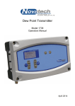
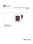
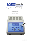
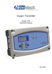
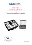
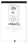
Carbon Controller
Model 1734
Operators Manual
November 2009
TABLE OF CONTENTS
TABLE OF CONTENTS .................................................................................................................................... 1 1. USING THIS MANUAL ................................................................................................................................. 3 1.1 CAUTIONS .................................................................................................................................................. 3 1.2 CONNECTING THE CONTROLLER TO THE POWER SUPPLY ............................................................................. 4 1.3 MOUNTING POSITION OF THE CONTROLLER ................................................................................................. 4 1.4 WARNING SYMBOLS ................................................................................................................................... 4 2. INTRODUCTION ........................................................................................................................................... 5 3. SPECIFICATIONS......................................................................................................................................... 7 3.1 HARDWARE SPECIFICATIONS ....................................................................................................................... 7 3.2 OPERATIONAL SPECIFICATIONS ................................................................................................................... 8 3.3 HEATER INTERLOCK RELAYS ....................................................................................................................... 9 4. DISPLAY AND KEYPAD ............................................................................................................................ 11 4.1 DISPLAY ................................................................................................................................................... 11 4.2 KEYPAD ................................................................................................................................................... 12 4.2.1 KEYPAD IN RUN MODE ...................................................................................................................... 12 4.2.2 KEYPAD IN SETUP MODE .................................................................................................................... 13 4.2.3 INFORMATION SCREEN ....................................................................................................................... 13 5. SETUP MODE ............................................................................................................................................. 15 5.1 SETUP MODE FUNCTION SUMMARY ........................................................................................................... 15 5.2 SETUP MODE DETAILS .............................................................................................................................. 15 5.2.0 TO CHANGE AN OPTION IN THE SETUP MENU ...................................................................................... 15 5.2.1 PROBE 1 & PROBE 2 OFFSET ............................................................................................................. 16 5.2.2 LOWER LINE ITEMS ............................................................................................................................ 16 5.2.4 DAMPING FACTOR .............................................................................................................................. 17 5.2.5 PROCESS ALARMS ............................................................................................................................. 17 5.2.6 CARBON CONTROLLER ....................................................................................................................... 17 5.2.3 CARBON SET POINT ........................................................................................................................... 18 5.2.6 HIGH CARBON ALARM & ALARM DELAY ............................................................................................... 18 5.2.7 LOW CARBON ALARM & ALARM DELAY................................................................................................ 19 5.2.8 CARBON DEVIATION ALARM & ALARM DELAY ....................................................................................... 19 6. ALARMS ..................................................................................................................................................... 21 6.1 CHECKING AND ACCEPTING AN ALARM ...................................................................................................... 21 6.1.1 CURRENT ALARMS ............................................................................................................................. 22 6.1.2 ALARM LOG ....................................................................................................................................... 22 6.2 ALARM RELAYS ........................................................................................................................................ 22 6.3 COMMON ALARMS .................................................................................................................................... 22 6.4 SELECTABLE PROCESS ALARMS ................................................................................................................ 24 6.5 WARNING MESSAGES ............................................................................................................................... 24 7. PROBE PURGE .......................................................................................................................................... 25 7.1 NOTES ON PURGING THE PROBE ................................................................................................................ 25 7.2 ACTIONS THAT OCCUR WHEN THE GAS SOLENOID KEYS ARE PRESSED ....................................................... 26 8. UPDATING THE SOFTWARE .................................................................................................................... 27 9. INDEX .......................................................................................................................................................... 28 March 2009
1734 carbon controller
Operators Manual
1
© Copyright NOVATECH CONTROLS PTY LTD — 2009
This manual describes the controller firmware version 1.00, November 2009
Neither the whole nor any part of the information contained in, or the product described in, this manual may
be adapted or reproduced in any material form except with the prior written approval of Novatech Controls
Pty Ltd (Novatech).
The product described in this manual and products for use with it are subject to continuous developments
and improvement. All information of a technical nature and particulars of the product and its use (including
the information in this manual) are given by Novatech in good faith. However, it is acknowledged that there
may be errors or omissions in this manual. A list of details of any amendments or revisions to this manual
can be obtained upon request from Novatech Controls Technical Enquiries. Novatech Controls welcome
comments and suggestions relating to the product and this manual.
All correspondence should be addressed to: Technical Enquiries
Novatech Controls Pty Ltd
309 Reserve Road,
Cheltenham
Victoria 3192
Australia
Tel:
Fax:
Email:
Web site:
+61 3 9585 2833
+61 3 9585 2844
[email protected]
http://www.novatech.com.au/
Novatech Controls or their authorised dealers should carry out all maintenance and service on the product.
Novatech Controls can accept no liability whatsoever for any loss or damage caused by service or
maintenance by unauthorised personnel. This manual is intended only to assist the reader in the use of the
product, and therefore Novatech Controls shall not be liable for any loss or damage whatsoever arising from
the use of any information or particulars in, or any error or omission in, this manual, or any incorrect use of
the product.
Operators Manual
2
November 2009
1734 carbon controller
1. USING THIS MANUAL
This manual is intended to be used by the operator. It is not intended to describe how the 1734 carbon
controller should be connected, configured or serviced. If more detailed information is required than is
shown in this manual the 1734 Technical Manual should be used. This is supplied with each controller and
is also available on the Novatech web site at www.novatech.com.au
It is assumed in this manual that the controller has been installed by competent personal and that the wiring
to the main power supply, the carbon probe and all the associated signal devices complies with the local
safety codes and regulations.
1.1 Cautions
Please read the safety information below before connecting power to the controller.
CAUTION
Please note that if this equipment is not installed and used in the manner described in this manual then the
safety protection provided by the equipment may be impaired.
March 2009
1734 carbon controller
Operators Manual
3
1.2 Connecting the Controller to the Power Supply
•
•
•
•
•
•
The mains power must be either 100/110VAC or 220/240VAC with a mains frequency of 50 or 60Hz
The supply circuit must be fused to at least 10Amps and have a dual pole isolation switch within
easy access of the carbon controller. The isolation switch must be marked as the isolation switch for
this equipment. It is recommended that a separate isolation switch be used for each controller so
that a controller can be serviced individually.
The power supply cables must be supplied and installed according to local regulations
The earth connection must comply with the local regulations must have a current carrying capability
equal or greater than the supply fuse current rating
The earth connection must be connected to the primary earth stud inside the controller on the right
hand side
All other bonded earth connections from the external wiring must be connected to the primary earth
stud
1.3 Mounting Position of the Controller
•
•
•
The controller should be mounted in a position where the ambient temperature will not exceed
55°C/130°F or be less than -25°C/-10°F ambient temperature
It must not be exposed to:o radiation from appliances such as ovens or furnaces
o direct sunlight
o rain, snow or sleet
The ventilation must be adequate to remove excess heat build up from the internal circuit of the
controller
1.4 Warning Symbols
Danger, high voltage. Risk of electrical shock.
Caution hot surface.
Caution, risk of danger. See additional information in the manual.
Operators Manual
4
November 2009
1734 carbon controller
2. INTRODUCTION
The Novatech 1734 Carbon Controller provides in-situ measurement for one or two carbon probes in furnace
and gas generators with temperatures up to 1400°C. The controller provides local indication of carbon
percentage and oxygen, plus numerous other related measurements.
Within the same process either one or two probes can be controlled providing average and/or individual
probe readings. The controller provides two isolated 4-20mA outputs, 4 normally closed configurable relay
outputs and digital communications via MODBUS. Alarms are displayed at the controller and the relay
contacts can be configured to activate remote alarm devices. Using unheated Novatech zirconia carbon
probes the analyser also provides automatic probe filter purging.
The model 1734 carbon controller is based on the well known model 1634 controller. It includes a number of
hardware and software improvements such as a graphic display, larger characters, faster microprocessor,
simplified set up menu, alarm logging, faster probe heater control and more accuracy in the calculation of
carbon.
The 1734 Carbon Controller has a variety of user-selectable functions. The device is configured locally using
a menu driven interface and the local keypad & display. For a description of the configuration process refer
to Chapter Error! Reference source not found.
Features include:Inputs
Two Novatech zirconia carbon / oxygen probes
Carbon range up to 2.0%
-30
Oxygen range from 10 to 100%
Furnace or auxiliary thermocouple, field selectable as type K, J, R, S or N
Purge pressure or flow switch
Outputs
Two linearised 4-20mA or 0-20mA DC isolated outputs, max. load 1000Ω
The output function and the range are field selectable
Common alarm relay
Three other alarm relays with selectable functions
Digital Interface
RS-232 or RS-485 MODBUS™ for connection to a computer/DCS/PCL for diagnostics of the controller,
probe or combustion process.
Display
Multi font graphical display
Large font characters for the carbon % on the top line
Selectable lower line items for the secondary display functions. ie Probe temperature, carbon %
measurement on the second probe, oxygen etc
Alarm display mode that shows the time of the alarm, the acceptance time and the time that the alarm was
cleared of up to 4000 alarm events
Power
Universal mains supply voltage, 100 to 240VAC
Automatically detects the mains voltage and frequency and set the power control accordingly
March 2009
1734 carbon controller
Operators Manual
5
This page has been intentionally left blank.
Operators Manual
6
November 2009
1734 carbon controller
3. SPECIFICATIONS
3.1 Hardware Specifications
Number of carbon probes:
2 maximum
Carbon range:
up to 2.0%
Oxygen range:
1 x 10
Oxygen accuracy:
±1% of actual measured oxygen value with a repeatability of ±0.5% of the measured
value
Thermocouple types:
Type K, J, R, S & N
Temperature accuracy:
±2°C
Analogue outputs:
0-20mA or 4-20mA field selectable
Active outputs (Do NOT loop power these outputs)
Output load:
1000 ohm max
Alarm relays:
4
Alarm relay contacts:
2A/240VAC, 2A/30VDC
-30
to 100%
(WARNING: Do not use both mains voltage and low voltage connections to adjacent alarm contacts)
Mains voltage supply:
Overvoltage:
100 to 240VAC, -6 +10%, 50/60 Hz
Category II (IEC60364-4-443)
Power:
5W for controller plus probe power
Fuses:
3A, fast blow, 250v, 20x5mm (heater fuses, 2 of)
1A, slow blow, 250v, microfuse (PCB mtg fuse, 1 of)
Environmental Rating:
Operating Temperature -25°C to 55°C
Relative Humidity 5% to 95% (non-condensing)
2000m maximum
Altitude
Degree of Protection:
IP65
IP54 with internal reference air pump
Case Size:
260mm (10.2”) wide, 160mm (6.3”) high, 90mm (3.5”) deep
Weight:
3 Kg (6.6 lbs.)
WARNING: All signal level connections onto the controller must be treated as safety extra-low voltage (SELV) as
defined in the standard IEC61140. Double insulation must be used when connecting these terminals to systems
that might carry high voltage.
March 2009
1734 carbon controller
Operators Manual
7
3.2 Operational Specifications
The 1734 controller has two fully configurable 4-20mA analogue outputs. The channels can be configured
independently to output one of several calculated values.
The following outputs are available on channel #1:
Output
Zero
Span
Step
Min Span
Default
Probe 1 Carbon %
0%
0.1 to 1.5%
0.1%
0.1%
0 to 1.5%
Average Carbon % **
0%
0.1 to 1.5%
0.1%
0.1%
0 to 1.5%
Probe 1 EMF
0 to 1400mV
100 to 1500mV
100mV 100mV
0 to 100mV
Probe 1 TC Temperature
0 to 1500°C
100 to 1600°C
100°C
100°C
0 to 1300°C
Probe 1 Oxygen %
0 to 99%
1 to 100%
0.1%
1%
0 to 25%
Reducing Oxygen 1 exp
+2 to -28
0 to -30
1
2 decades
-1 to 30
Aux TC Temperature *
0 to 1500°C
100 to 1600°C
100°C
100°C
0 to 1300°C
No Output
** Only available in dual probe mode.
* Only available in single probe mode.
The following outputs are available on channel #2:
Output
Zero
Span
Step
Min Span
Default
Probe 1 Carbon % *
0%
0.1 to 1.5%
0.1%
0.1%
0 to 1.5%
Probe 2 Carbon % **
0%
0.1 to 1.5%
0.1%
0.1%
0 to 1.5%
Average Carbon % **
0%
0.1 to 1.5%
0.1%
0.1%
0 to 1.5%
Probe 1 EMF *
0 to 1400mV
100 to 1500mV
100mV 100mV
0 to 100mV
Probe 2 EMF **
0 to 1400mV
100 to 1500mV
100mV 100mV
0 to 100mV
Probe 1 TC Temperature *
0 to 1500°C
100 to 1600°C
100°C
100°C
0 to 1300°C
Probe 1 TC Temperature **
0 to 1500°C
100 to 1600°C
100°C
100°C
0 to 1300°C
Probe 1 Oxygen % *
0 to 99%
1 to 100%
0.1%
1%
0 to 25%
Probe 1 Oxygen % **
0 to 99%
1 to 100%
0.1%
1%
0 to 25%
Reducing Oxygen 1 exp. *
+2 to -28
0 to -30
1
2 decades
-1 to 30
Reducing Oxygen 2 exp. **
+2 to -28
0 to -30
1
2 decades
-1 to 30
Aux TC Temperature *
0 to 1500°C
100 to 1600°C
100°C
100°C
0 to 1300°C
No Output
** Only available in dual probe mode.
* Only available in single probe mode.
The zero and span of the selected output are set in the following two menus (functions 11&12 and 14&15).
Range of local indication:
The measurement of carbon is shown as the main and largest value on the display. It is shown with 2
decimal places as #.## %.
The measured oxygen content displayed on the Lower line is shown in either %, or in scientific notation.
The format of the oxygen display changes to maintain the best resolution for the measurement.
Range
Display format
30.0 to 100.0%
##.#%
1.00 to 29.99%
##.##%
0.100 to 0.999%
#.###%
< 0.100%
scientific notation (#.## x 10 - ## % )
Operators Manual
8
November 2009
1734 carbon controller
Local display, secondary functions:
This function allows the operator to change the items that are available to be displayed on the lower line of
the controller in RUN mode. If the word “Enabled” appears on the display for a selected lower line option,
the measurement will be available to be shown on the display in the RUN mode by scrolling through the list
using the DISPLAY UP and DISPLAY DOWN keys.
A lower line measurement can be “Enabled” or disabled by pressing the ENTER key.
1
2
3
4
5
6
7
8
9
10
11
12
13
14
18
19
OPTIONS:
Probe 2 Carbon %
Average Carbon %
Probe 1 TC Temperature
Probe 2 TC Temperature
Probe 1 EMF mV
Probe 2 EMF mV
Probe 1 Sensor Impedance
Probe 2 Sensor Impedance
Probe 1 Oxygen %
Probe 2 Oxygen %
Auxiliary TC Temperature
Ambient Temperature
Ambient Relative Humidity
Controller Set Point
Burner Run Time
Service date
Enabled as Default
*
*
*
*
*
*
*
*
*
NOTE: An asterisk (*) on the end of the line identifies the item is enabled by default after a COLD-START.
3.3 Heater Interlock Relays
When the solenoid outputs
are to be used a link must be
installed as shown.
10
BURNER INPUT
11
Heater Supply Interlock Connection for Heated Probes
If the solenoid outputs are to be used, a link must be installed between terminals 10 &11 to enable –
• Carbon control using ON/OFF control
• Carbon control using proportional ON/OFF control
• Carbon control using an up/down motor drive control
• Auto-purge and auto-cal checking.
March 2009
1734 carbon controller
Operators Manual
9
This page has been intentionally left blank.
Operators Manual
10
November 2009
1734 carbon controller
4. DISPLAY AND KEYPAD
The 1734 controller has a graphic display, 8 keys that are accessed from the outside of the cabinet and 5
LED indicators to show the status of the controller. All the keys have a dual function. The black text on the
key is the function while the controller is in the RUN mode and the white text on the key is the function in the
SETUP mode.
The SETUP mode is accessed by pressing the SETUP key. The controller will return to the RUN mode
when the SETUP key is pressed again or one minute after the last key is pressed.
The front panel of the model 1734 carbon controller
4.1 Display
The 1734 display is used to show the carbon percentage in a large font and the secondary functions in a
smaller font. The default display is shown below with probe #1 carbon on the top line and the probe #1
temperature on the lower line.
Heartbeat
indicator
POWER
CARBON CONTROLLER
Power on
indicator
1734
Carbon measurement, probe 1
N/A (Not Available) will be
shown when probe 1 is below
550 °C (1022°F)
0.98%
Probe 1 TC 1020.3 C
Activity indicator
(see below for
details)
B
14:20:36
Lower line,
secondary measurements
Current time
In addition to displaying the current carbon and the various secondary values, the display is also used to
show the current and active alarm conditions and to configure the controller. This is achieved by entering the
SETUP mode (see chapter 5). The backlight will turn off if the case temperature is over 35°C. It will come
on again as soon as a key is pressed and remain on for 60 seconds.
The Activity indicators show actions that are happening in the background.
B
The burner input has been enabled (terminals 10&11)
A
The controller is doing an auto calibration. This happens every minute or when the AUTO CAL keyis
pressed in setup mode
T
(Flashing) The probe(s) is(are) below operating temperature (650°C/1200°F)
Z
The controller is doing an impedance check of the probe(s).
March 2009
1734 carbon controller
Operators Manual
11
4.2 Keypad
There are 8 keys built into the decal on the outside of the door of the 1734 carbon controller. The key
function is printed in BLACK and WHITE to identify the function of the key in either RUN mode or SETUP
mode.
Key text
SETUP / RUN
DISPLAY / FUNCTION Δ
DISPLAY / FUNCTION ∇
ALARM / OPTION Δ
ALARM / OPTION ∇
ALARM ACCEPT / ENTER
GAS 1 PURGE 1 / SENS IMP
GAS 2 PURGE 2 / AUTO CAL
RUN mode (WHITE text)
Enter SETUP mode
Display scroll up
Display scroll down
Alarm scroll up
Alarm scroll down
Alarm accept
Gas 1 / Purge 1 manual activate
Gas 2 / Purge 2 manual activate
SETUP mode (BLUE/BLACK text)
Return to RUN mode
Function scroll up
Function scroll down
Option scroll up
Option scroll down
Enter
Probe impedance
Auto calibrate
4.2.1 Keypad in RUN Mode
When the controller is turned on, and has gone through the start-up procedure, it will go to the RUN mode.
In this mode the top line of the display will show the carbon measurement from probe 1. The other key
functions are –
SETUP / RUN Key
Pressing this key once will put the controller into the SETUP mode. The function of all the keys will then
change to the functions that they have in the SETUP mode. Pressing the SETUP / RUN key again will return
the controller to the RUN mode, or it will return automatically one minute after the last key press.
DISPLAY UP / DISPLAY DOWN Keys
The display keys are used to scroll the lower line up and down through the variety of measurements that are
available on the lower line display. The list can be changed to suit the operator by using SETUP function #3.
ALARM UP Key
If there is either a new alarm or an active alarm the ALARM UP key can be pressed to examine the alarm
status. The alarm light will be flashing if there is a new alarm or steady if there is an existing alarm. (see
chapter 6, Alarms).
ALARM DOWN Key
When the controller is in the run mode or the alarm mode (the ALARM UP key has been pressed), the
ALARM DOWN key and the ALARM UP key allow the operator to examine the alarm log. The date / time of
last 4000 alarms can be scrolled through. Each alarm record consists of the alarm name and the date / time
that the alarm was initiated, accepted and cleared (see chapter 6, Alarms).
ALARM ACCEPT Key
The ALARM ACCEPT key is used to accept a new alarm (see chapter 6, Alarms).
GAS 1 / PURGE 1 and GAS 2 / PURGE 2 Keys
These two keys are used to turn on the purge solenoids. When the controller is in the manual purge mode
(Commissioning function #21 & 26) the solenoid will be activated for as long as the key is pressed. When
the controller is in the auto purge mode the automatic purge cycle is started. The cycle can be stopped by
pressing any key. (See chapter 7, Probe Purge)
Operators Manual
12
November 2009
1734 carbon controller
4.2.2 Keypad in Setup Mode
When the SETUP / RUN key is pressed once, the controller will go into the SETUP mode.
For information about the additional user-selectable options, see the 1734 Technical Manual.
The following key functions are then available in the SETUP mode.
SETUP / RUN key
Pressing this key once will put the controller into the SETUP mode. The function of all the keys will then
change to the functions that they have in the SETUP mode. Pressing the SETUP / RUN key again will return
the controller to the RUN mode, or it will return automatically one minute after the last key press.
FUNCTION UP / FUNCTION DOWN Keys
These two keys allow the selection of the required setup function from the list shown at the start of chapter
5.1 (Setup Mode Function Summary).
OPTION UP / OPTION DOWN keys
These two keys allow for the selection of the options that are available in the selected function. See the
details of these in chapter 5.2 (Setup Mode Details).
ENTER key
The ENTER key saves the selected option. If the ENTER key is not pressed when a new option is chosen,
the previous option will be retained.
SENSOR IMPEDANCE key
When this key is pressed the controller will measure the impedance of the sensor in the probe(s). This will
only happen if the burner is enabled (terminals 10 and 11) and the probe temperature is over 700°C/1290°F.
AUTO CALIBRATE key
When this key is pressed the controller will calibrate the analog output channels. This is done by directing
the output current away from the output terminals (terminals 12 &13 and 14 & 15) and directing the current
back into the controller input. The controller will then calculate a zero and a span calibration factor for each
of the output channels. The output calibration will only happen if the channel is not set to manual output
calibration. (See Technical Manual for more details)
4.2.3 Information Screen
The 1734 carbon controller has an information screen available to the user to allow more detailed information
about the running of the controller to be easily read by the user.
The information available is:
1. Model and version of the current firmware
2. The date/time that the firmware was compiled
3. The maximum temperature that the controller has measured inside the cabinet
4. Current date and time
5. The time of all the next timed events (Impedance test, cal/purge 1, cal/purge 2)
6. ADC calibration data (analogue input calibration)
7. DAC calibration data (analogue output calibration)
8. Probe temperature record (probe 1 and 2)
The information screen is entered from the run mode by pressing (and holding) the ALARM ACCEPT key
and then pressing the SETUP key. The first data appears at the top of the screen and there is a scroll bar
down the left hand side. The data can be scrolled through by using the DISPLAY up and down keys. The
data cannot be changed.
The output and control functions continue as normal while the information screen is being displayed. The
normal display is resumed by pressing the set-up key.
March 2009
1734 carbon controller
Operators Manual
13
This page has been intentionally left blank.
Operators Manual
14
November 2009
1734 carbon controller
5. SETUP MODE
This chapter describes the functions available when the SETUP mode is selected on the controller.
The SETUP mode is accessed by pressing the SETUP key. The controller will return to the RUN mode
when the SETUP key is pressed again or 1 minute after the last key is pressed.
5.1 Setup Mode Function Summary
When the controller is in the SETUP mode the SETUP light will be on. The following table shows the SETUP
menu functions:
Menu # Function name (top line)
01
Probe 1 offset
02
Probe 2 offset
03
Lower line items
Range
-6.0 to +6.0mV
-6.0 to +6.0mV
-
04
Damping factor
05
06
07
08
09
10
11
12
13
Process alarms
Carbon controller
Carbon & set point
High carbon alarm
High carbon alarm delay
Low carbon alarm
Low carbon alarm delay
Carbon Deviation alarm
Carbon Deviation alarm delay
No damping to
10 samples averaged
Enabled / Disabled
0.01 to 2.00%
0.01 to 2.00%
0 to 200 seconds
0.01 to 2.00%
0 to 200 seconds
0.01 to 2.00%
0 to 200 seconds
Default value
0.0mV
0.0mV
See SETUP function #3
for details (chapter 5.2.2)
5 samples averaged
Disabled
See chapter 5.2.6
1.20%
1.50%
20 seconds
0.35%
20 seconds
2.00%
30 seconds
5.2 Setup Mode Details
Power on
indicator
POWER
CARBON CONTROLLER
Function
name
1734
Function
number
Selected
option
Activity Indicator
A or Z
See chapter 4.1
01 Probe 1 Offset
+0.0 mV
Saved
Verification that the
selected option has
been saved
Setup Menu
Menu name
5.2.0 To Change an Option in the Setup Menu
1. Select the SETUP mode by pressing the SETUP / RUN key once. The SETUP light will come on
and the display will have the format shown above. The operations of the keys are now the
operations written in white on the keypad. The menu name is written at the bottom of the display.
2. When the SETUP mode has been selected the required function can be found by using the
FUNCTION UP and FUNCTION DOWN keys.
3. The options available for that function can be seen by using the OPTION UP and OPTION DOWN
keys.
4. When the required option is on the display the ENTER key is used to save that option.
5. Press the SETUP / RUN key to return to the RUN mode.
The details of each function are given below.
NOTE: An asterisk next to a listed option denotes default state after a COLD-START
March 2009
1734 carbon controller
Operators Manual
15
5.2.1 Probe 1 & Probe 2 Offset
POWER
CARBON CONTROLLER
POWER
CARBON CONTROLLER
1734
01 Probe 1 Offset
1734
02 Probe 2 Offset
+0.0 mV
+0.0 mV
Saved
Saved
Setup Menu
Setup Menu
Each Novatech probe has an offset calibration value printed on a tag that is attached to the probe when it is
dispatched. The offset value must be entered into this setup function to achieve the most accurate
measurements. The value is usually between -1.0 to +1.0mV.
RANGE:
-6.0 to +6.0mV (0.0mV is set after a COLD-START)
NOTE: An error of 1mV in the probe offset will change the carbon reading by about 0.01% carbon.
The function ’02 Probe 2 Offset’ will only appear if the controller has been configured for 2 probes.
5.2.2 Lower Line Items
POWER
CARBON CONTROLLER
1734
03 Lower Line Items
Probe 1 EMF
Enabled
Setup Menu
This function allows the operator to change the items that are available to be displayed on the lower line of
the controller when it is in the RUN mode. If the word “Enabled” appears on the display for a selected lower
line measurement option, the measurement will be available to be shown on the display in the RUN mode by
scrolling through the list using the DISPLAY up and DISPLAY down keys.
A lower line selection can be “Enabled” or disabled by pressing the ENTER key.
OPTIONS:
Probe 2 Carbon %
Average Carbon %
Temperature, Probe #1
Temperature, Probe #2
Sensor EMF, Probe #1
Sensor EMF, Probe #2
Sensor Impedance, Probe #1
Sensor Impedance, Probe #2
*
**
*
*
*
*
*
*
Oxygen, Probe #1
Oxygen, Probe #2
Ambient Temperature
Ambient RH%
Controller Set Point
Burner Run Time
Service Date
Auxiliary TC Temperature
*
*
*
NOTE: An asterisk (*) identifies the item is enabled by default after a COLD-START.
Operators Manual
16
November 2009
1734 carbon controller
5.2.4 Damping Factor
POWER
CARBON CONTROLLER
1734
04 Damping Factor
5 x Sampling
Saved
Setup Menu
The carbon measurement can be damped if there are annoying fluctuations in the process gas. Of course
any damping will slow down the reaction time of the controller. The larger the number selected here, the
steadier the measurement will be.
The damping factor is also used to damp the oxygen measurement and the damped oxygen value is also
used in the calculation of all other parameters that are based on the oxygen value.
RANGE: “No Damping” to 10
(5 x Samples is set after a COLD-START)
5.2.5 Process Alarms
POWER
CARBON CONTROLLER
1734
05 Process Alarms
Disabled
Saved
Setup Menu
This function allows the operator to “Disable” process alarms.
Setup functions 7 to 14 show the alarm trip points that have been set in the controller.
OPTIONS:
Enabled
Disabled
*
5.2.6 Carbon Controller
POWER
CARBON CONTROLLER
1734
06 Carbon Controller
ON/OFF Control
Saved
Setup Menu
The 1734 is able to control the atmosphere to a specific carbon value. The type of control selected here will
depend on the gas control valve being used.
March 2009
1734 carbon controller
Operators Manual
17
Disabled (No control)
*
OPTIONS:
ON/OFF Control
Proportional ON/OFF Control
Proportional + Integral 4-20mA
Floating Control
5.2.3 Carbon Set Point
POWER
CARBON CONTROLLER
1734
07 Carbon Set Point
1.20 %
Saved
Setup Menu
If a carbon controller type has been selected in the previous function, a set point carbon value can be
entered here. The 1734 controller will operate the gas control valve to maintain the set point carbon in the
process.
OPTIONS:
Carbon % 0.01 to 2.00
(1.20% is set after a COLD-START)
5.2.6 High Carbon Alarm & Alarm Delay
NOTE: These menu functions are read only. To change these settings see, the Technical Manual.
POWER
CARBON CONTROLLER
POWER
CARBON CONTROLLER
1734
08 High Carbon Alarm
1.50 %
1734
09 High Carbon Delay
20 seconds
Locked
Setup Menu
Locked
Setup Menu
If the controller has been selected to run a single probe, it will show a high carbon alarm when the carbon
measurement of probe 1 goes above the trip level for longer than the delay time.
If the controller has been selected to run dual probes, it will show a high carbon alarm when the average of
the two carbon measurements is below the trip level for longer than the delay time. If either one of the
probes has a failure alarm (High sensor impedance, thermocouple open circuit, heater failure) the alarm will
then trip on the carbon measurement from the remaining working probe alone.
RANGE:
RANGE:
0.01 to 2.00 %
0 to 200 seconds
Operators Manual
18
(1.50 % is set after a COLD-START)
(20 seconds is set after a COLD-START)
November 2009
1734 carbon controller
5.2.7 Low Carbon Alarm & Alarm Delay
NOTE: These menu functions are read only. To change these settings see, the Technical Manual.
POWER
CARBON CONTROLLER
POWER
CARBON CONTROLLER
1734
1734
11 Low Carbon Delay
10 Low Carbon Alarm
0.35 %
.
20 seconds
Locked
Locked
Setup Menu
Setup Menu
If the controller has been selected to run a single probe, it will show a low carbon alarm when the carbon
measurement of probe 1 goes below the trip level for longer than the delay time.
If the controller has been selected to run dual probes, it will show a low carbon alarm when the average of
the two carbon measurements is below the trip level for longer than the delay time. If either one of the
probes has a failure alarm (High sensor impedance, thermocouple open circuit, heater failure) the alarm will
then trip on the carbon measurement from the remaining working probe alone.
RANGE:
RANGE:
0.01 to 2.00 %
0 to 200 seconds
(2.5 % is set after a COLD-START)
(20 seconds is set after a COLD-START)
5.2.8 Carbon deviation Alarm & Alarm Delay
NOTE: This menu function is read only. To change this setting, see the Technical Manual.
POWER
CARBON CONTROLLER
POWER
CARBON CONTROLLER
1734
12 Carbon Dev’n Alarm
2.00 %
1734
13 Carbon Dev’n Delay
.
30 seconds
Locked
Setup Menu
Locked
Setup Menu
If the controller has been selected to run a single probe, these two functions will be hidden.
If the controller has been selected to run dual probes, it will show a carbon deviation alarm when the
deviation of the two carbon measurements is above the trip level for longer than the delay time. If either one
of the probes has a failure alarm (High sensor impedance, thermocouple open circuit, heater failure) the
alarm will not operate.
RANGE:
RANGE:
0.01 to 2.00 %
0 to 200 seconds
March 2009
1734 carbon controller
(2.00 % is set after a COLD-START)
(30 seconds is set after a COLD-START)
Operators Manual
19
This page has been intentionally left blank.
Operators Manual
20
November 2009
1734 carbon controller
6. ALARMS
The 1734 controller has 4 alarm relays and a built in alarm annunciator and an alarm log. When an alarm
occurs and the ALARM up key is pressed, the controller goes into the alarm display mode. In this mode
some of the keys take on a special function.
Key text
SETUP / RUN
DISPLAY / FUNCTION up
DISPLAY / FUNCTION down
ALARM / OPTION up
ALARM / OPTION down
ALARM ACCEPT / ENTER
RUN mode
Enter ALARM display mode
Enter ALARM log mode
ALARM mode
Return to RUN mode
Next alarm time
Previous alarm time
Next Alarm
Previous Alarm
Accept alarm
When the alarm mode has been entered the SETUP light flashes once a second.
All relays have fail-safe alarm contacts. That is –
When the controller is off the contacts are open circuit
When the controller is on but there are no alarms the contacts are closed
When there is a current alarm event the contacts are open circuit
All alarms drive the alarm light on the front door.
The light will be off if there are no alarms current
The light will flash if there is a current alarm that has not been accepted
The light will be on steady if there are current alarm(s) that have been accepted
The light will flash faster as more alarms occur
6.1 Checking and Accepting an Alarm
When a new alarm occurs, either a process alarm or an alarm that will appear in the common alarm list, the
ALARM light will flash. The more new alarms there are, the faster the light will flash.
To check the cause of the alarm –
1. Press the ALARM up key. This will put the controller into the current alarm mode. The SETUP light
will flash.
2. The alarm screen will appear displaying the cause of the alarm on the top line.
Cause of the alarm
POWER
CARBON CONTROLLER
1734
Probe 1 TC Open/Ct
Time Activated:
13 Apr 2006 13:05:28
Status:
Active
Time title:
Time Activated
Time Accepted
Time Cleared
Time of the
event
Alarm status:
Active
Accepted
Self cleared
3. Press the ALARM ACCEPT key to accept the alarm.
4. Press the OPTION up key to see the next active alarm or the OPTION down to see the previous
active alarm.
5. When all the new alarms have been ACCEPTED the ALARM light will stop flashing.
6. Accept each alarm and then press the SETUP / RUN key to return to the run mode.
March 2009
1734 carbon controller
Operators Manual
21
6.1.1 Current Alarms
To view the alarms that are still current press the ALARM up key from the RUN mode and then use the
ALARM up and down keys to view all alarms. Use the DISPLAY up and down keys to view the Time
Activated, Time Accepted and the Time Cleared of each alarm.
6.1.2 Alarm Log
The alarm log keeps a record of the alarm events after the cause of the alarm has been cleared. It will hold
a record of up to 1000 alarm events and will be retained even with the controller power off.
To view all the alarms that have occurred in the alarm log press the ALARM down key from the RUN mode.
The display will look like this:
Cause of the alarm
POWER
CARBON CONTROLLER
1734
Probe 2 TC Open/Ct
Time Activated
08 Mar 2009 03:45:29
Alarm Log (0002/0057)
Time title:
Time Activated
Time Accepted
Time Cleared
Time of the event
Number of the alarm being viewed /
Total number of alarms in the log
Use the OPTION up and down to scroll through the alarm events that have been saved in the alarm log. The
alarm event will be transferred to the alarm log when the alarm has been cleared.
The alarms are stored in the alarm log in chronological order. However, it may be seen that the current
alarm number will skip some numbers. These numbers have been reserved for alarm events that are still
current. When the alarm cause has been removed, these alarm events will be transferred to the alarm log.
6.2 Alarm Relays
The common alarm relay is used to monitor faults within the controller and the probe. The list of events that
will cause the common alarm relay to be activated is shown in chapter 6.3, Common Alarms. The relay
contacts will be open circuit if there is a current alarm condition.
The other three alarm relays are user defined and are used to monitor the process. The function of the
process alarm relays is user selectable. See chapter 6.4, Selectable Process Alarms, and the Technical
Manual for further information.
6.3 Common Alarms
The events that drive the common alarm relay are –
1. ‘Probe 1 Heater Fail’
2. ‘Probe 2 Heater Fail’
If a heated probe has been selected, in the first 20 minutes of power being applied to the heater after being
switched on, this alarm will not occur, but a ‘T’ display will be shown on the bottom of the display. If an ADC
alarm occurs, the heaters will automatically be turned off. If the probe has not reached 650°C/1200°F in 20
minutes the ‘Probe 1(2) Heater Fail’ alarm will be raised.
3. ‘Probe 1 High Impedance’
4. ‘Probe 2 High Impedance’
Carbon probe or electrode failure (high impedance). This alarm is inhibited when the probe temperature is
under 650°C/1200°F.
Operators Manual
22
November 2009
1734 carbon controller
5. ‘Probe 1 TC Open Circuit’
6. ‘Probe 2 TC Open Circuit’
Probe thermocouple is open circuit. The heater in heated probes will switch off.
7. ‘Auxiliary TC Open Circuit’
Stack thermocouple is open circuit. If the thermocouple is not needed, select “NO T/C” for “Aux TC Type” or
place a short circuit between terminals 7 & 8.
8. ‘Reference Air Pump Fail’
The reference air pump in the controller is either disconnected or is drawing <20mA.
9. ‘Reference Air Pump Overload
The reference air pump in the controller has drawn >300mA. The power will be turned off to the pump to
avoid damage to the pump driving circuit. The 1734 controller will attempt to restart the pump every minute.
To force a restart, disconnect the pump and reconnect it.
10. ‘ADC Calibration Fail’
The analog to digital converter has been found to fall outside the normal calibration specifications. In this
case the probe heater will automatically be turned off.
11. ‘Alarm Log Fail’
The alarm history is kept in an EEROM. This alarm will be raised if this memory device fails.
12. ‘Output 1 Failure’
13. ‘Output 2 Failure’
The digital to analog and voltage isolator circuit has been found to fall outside the normal calibration
specifications. This check is only performed when the ‘AUTO CAL’ button is pressed.
Refer to chapter 4.2.2.
14. ‘Heater 1 SSR Failure’
15. ‘Heater 2 SSR Failure’
16. ‘Heater SSR Leakage’
The 1734 controller has the ability to monitor the operation of the heater current in a heated probe. As a
result, the controller will give an alarm within 1 second of a heater power control switch (Solid State Relay)
failure. If either of the SSR’s are found to be faulty, both heaters will be turned off immediately and the alarm
will be raised. The SSR must be replaced. The ‘SSR Leakage’ alarm will occur if one of the heater SSR’s
are partly shorted.
If probe #1 SSR has failed and only one probe is being used, the 1734 Technical Manual describes how the
SSR for probe #2 can be selected instead. If 2 probes are being used but neither of the solenoid outputs are
being used consult the Technical Manual.
17. ‘Probe 1 Filter Blocked’
18. ‘Probe 2 Filter Blocked’
Blocked probe filter. This test is only performed when automatic purging of the probe is selected. This alarm
will not reset until the next purge cycle. The cycle can be initiated manually or automatically.
19. ‘BBRAM Fail’
All of the setup options are held in the battery backed memory (BBRAM). This is the battery shaped device
at the bottom centre of the 1730-1 PCB labeled MEM1. This alarm will occur when this device fails and will
need to be replaced.
March 2009
1734 carbon controller
Operators Manual
23
6.4 Selectable Process Alarms
There are three user configurable alarm relays. Any or all of the following functions can be selected for each
relay.
The description of how the trip levels and the delay times are set is in the 1734 Technical Manual.
NOTE: The process alarms will only be activated if they are enabled in SETUP menu function 06.
20. ‘Carbon 1 Low
21. ‘Carbon 2 Low
The measured carbon level on the indicated probe has been below the trip level shown in setup function #10
for longer than the delay time shown in setup function #11.
22. ‘Carbon 1 High’
23. ‘Carbon 2 High’
The measured carbon level on the indicated probe has been above the trip level shown in setup function #08
for longer than the delay time shown in setup function #10.
24. ‘Carbon Deviation’
The difference between the carbon level measured on probe #1 and the carbon level measured on probe #2
is greater than the trip level shown in setup function #13 and the time delay shown in setup function #14 has
expired.
25. ‘Probe 1 Temperature Low’
26. ‘Probe 2 Temperature Low’
The probe temperature is under 650°C (1200°F). The carbon reading is therefore invalid. If the probe
heater has been on for more than 20 minutes and the temperature is less than 650°C (1200°F) a ‘Probe #
Heater Fail’ alarm will occur if a heated carbon probe is being used .
NOTE: The ‘Probe # Temperature Low’ relay function is used with unheated probes to indicate oxygen
reading is invalid (the probe is below 650°C (1200°F) ), in case the process temperature falls below this
level. With heated probes this relay will be de-energised while the probe is heating up from ambient, making
the contacts open circuit.
27. ‘Purge 1 in Progress’
28. ‘Purge 2 in Progress’
A probe purge is occurring, either manual or automatic mode.
29.
30.
31.
32.
‘Carbon 1 Invalid Low’
‘Carbon 2 Invalid Low’
‘Carbon 1 Invalid High’
‘Carbon 2 Invalid High’
The carbon within the process may not be valid due to the probe EMF resulting in a carbon potential that is
above/below the maximum carbon potential for the temperature of the process
6.5 Warning Messages
27. ‘Probe 1 Temperature Low’
28. ‘Probe 2 Temperature Low’
The probe temperature is under 650°C/1200°F. The carbon reading is therefore invalid. If a heated probe is
being used, the probe heater has been on for more than 20 minutes and the temperature is still less than
650°C/1200°F a ‘Probe 1(2) Heater Fail’ alarm will occur. There will be a flashing ‘T’ symbol on the bottom
left hand corner of the display until the temperature of the probe(s) is over 650°C/1200°F.
NOTE: The ‘Probe 1(2) Temperature Low’ function is also used with unheated probes to show that the probe
temperature is below 650°C/1200°F when the process temperature falls below this level.
31. ‘Purge 1 in Progress’
32. ‘Purge 2 in Progress’
A probe purge is occurring, either manual or automatic mode.
Operators Manual
24
November 2009
1734 carbon controller
7. PROBE PURGE
The Novatech oxygen sensor that is used in the Novatech carbon probe is extremely predictable, stable and
reliable. For this reason, the calibration of a Novatech carbon system does not require the use of calibration
gases.
However, it may be necessary to periodically purge a build up of carbon from around the sensor tip.
The 1734 controller has a timer and solenoid driving system that can be configured to admit an air supply to
purge the probe through the gas connection on the probe. The purge gas must be piped to the port on the
probe labelled “CAL/PURGE”.
There are two solenoid drivers in the 1734 carbon controller. They can be used to independently purge a
single probe if the 1734 controller has only one probe connected.
If the controller has two probes connected, one solenoid can be connected to two probes with a ‘T’ piece
tube connector, or the solenoids can be connected independently to each probe.
Single Probe
Configuration
Cal / Purge 1
Cal / Purge 2
Dual Probe
Configuration
Cal / Purge 1
Cal / Purge 2
Solenoid 1 should be connected to the purge gas and the gas connection on the
probe
No connection
Solenoid 1 should be connected to the purge gas and the gas connection on the
first probe
Or
a ‘T’ piece can be used on the purge line to purge 2 probes at a time
Solenoid 2 should be connected to the purge gas and the gas connection on the
second probe
The controller can also be configured to be in a MANUAL or AUTOMATIC purge mode.
The information on configuring the controller is contained in the 1734 Technical Manual.
7.1 Notes on purging the probe
Most probe failures are caused by probe sooting which can be avoided by regular in-situ cleaning. Passing a
stream of air through the probe on the outside of the sensor and into the furnace causes combustion. The
free oxygen behind the flame front will burn away the soot. However, the flame will also heat up the probe.
The location of the flame front will be determined by the balance between the air pressure and the air flow
against the furnace and the flow around the probe. This will depend on the furnace and its operating regime.
The conditions of the furnace atmosphere near the probe is of great importance when establishing the
correct flow rate of probe cleaning air. For example, if the furnace fan is switched off the furnace pressure
will change and tis will alter the flow rate of the purge air. The lower the probe mV during the more effective
the cleaning action will be. In most cases 3 – 5 litres per minute of air will be required.
It is bad practice the let the flame front remain at the probe tip as it can cause dramatic over heating and
probe damage. The probe signal should show greater oxygen levels if the cleaning process is working, and
typical cleaning should take 3 – 6 minutes, and should be carried out at the start of a cycle to ensure correct
operation during the process.
Care should be taken to avoid the combustion interface coinciding with the probe tip, a circumstance where
the probe temperature may rise more that 120°C.
March 2009
1734 carbon controller
Operators Manual
25
7.2 Actions that Occur when the Gas Solenoid Keys are Pressed
The 1734 carbon controller has a built in timer to operate the solenoid outputs. The menu functions allow
setting of the purge start time, the purge period, the purge duration and the output freeze time.
If a timer has not been enabled in the commissioning menu, pressing the GAS1(2) / PURGE1(2) key will turn
on the solenoid for as long as the key is pressed.
If the timer has been enabled in the commissioning menu, pressing the GAS1(2) / PURGE1(2) key will turn
on the solenoid for as long as the programmed duration has been set for.
Refer to the person responsible for the commissioning to find out how the controller has been configured.
Operators Manual
26
November 2009
1734 carbon controller
8. UPDATING THE SOFTWARE
The programme for 1734 carbon controller is run from memory that is inside the main microprocessor. The
programme is inserted at the time of manufacture. If the software needs to be updated to a later version, the
factory can supply an EEROM (electrically erasable read only memory) containing the update. The following
procedure should be used –
1.
2.
3.
4.
5.
Turn the power off to the controller
Remove the hose from the reference air pump (if fitted)
Unplug the reference air pump DC power lead (if fitted)
Remove the shield from the main PCB in the back of the cabinet by undoing the 2 M4 screws
Carefully remove the update EEROM from the packaging
NOTE: The EEROM is static sensitive. Avoid static discharges through the pins of the EEROM by earthing
yourself before picking up the EEROM.
6. Plug the EEROM into the 32 pin socket in the lower left hand corner of the main PCB
NOTE: Be very careful not to bend any of the pins of the EEROM. If the EEROM does not have all the pins
correctly plugged into the socket during upgrade the controller program may be destroyed and it will have to
be returned to Novatech for service.
Note also the direction of the EEROM. Pin 1 is identified by a small dot on the EEROM. The writing on the
EEROM label must be up the same way as the controller.
Pin 1 of the EEROM
1734 Ver. 1.01
7. While the power is still turned OFF, press and hold the DISPLAY DOWN and the ALARM LOG
DOWN keys. The following message should be shown on the display
8. If the message “Invalid EEROM, Unable to Upgrade” is displayed, turn the power off again and
check the pins of the EEROM and that it was in the correct direction.
9. If the display looks like the following image, press the DISPLAY UP key to load the upgrade software
Description of the
update software in the
EEROM
Press the DISPLAY UP key
to “Flash” the update and run
the new software version
10.
11.
12.
13.
14.
POWER
CARBON CONTROLLER
1735
Flash Update Firmware?
Model 1734
Version 1.02
Flash
Cancel
Press the ALARM UP key to
“Cancel” the update and run
the previous software
version
Turn the power off
Remove the EEROM and save it in the original packaging
Replace the main shield and secure it with the three screws.
Reconnect the reference air pump hose and plug (if fitted).
Turn the power back on without any keys pressed. The version number of the software will be
shown on the first screen.
NOTE: The EEROM can be used to upgrade any number of controllers
March 2009
1734 carbon controller
Operators Manual
27
9. INDEX
Alarms ............................................................................................................................................................................... 21
Alarms, Checking .............................................................................................................................................................. 21
Alarms, Common .............................................................................................................................................................. 22
Alarms, Process Enabling ................................................................................................................................................. 17
Alarms, Selectable ............................................................................................................................................................ 24
Alarms, Warning Messages ........................................................................................................................................ 24, 25
Calibration, Gas Check ..................................................................................................................................................... 25
Damping Factor................................................................................................................................................................. 17
Display, Run Mode ............................................................................................................................................................ 11
Display, Setup Mode ......................................................................................................................................................... 15
Heater Interlock Relays ....................................................................................................................................................... 9
Interlock............................................................................................................................................................................... 9
Key, Auto Calibrate ........................................................................................................................................................... 13
Key, Probe Impedance ...................................................................................................................................................... 13
Keypad .............................................................................................................................................................................. 12
Lower Line Changes ......................................................................................................................................................... 16
Probe Offset ...................................................................................................................................................................... 16
Setup Mode ....................................................................................................................................................................... 15
Specifications - Hardware ................................................................................................................................................... 7
Specifications - Operational ................................................................................................................................................ 8
Units, Oxygen Dispaly ................................................................................................................................................. 17, 18
Voltage, Mains Supply ........................................................................................................................................................ 7
Warnings ............................................................................................................................................................................. 3
Operators Manual
28
November 2009
1734 carbon controller
Declaration of Conformity
Application of Council Directives:
2004/108/EC
2006/95/EC
Standards to which conformity is declared:
EN50270:1999
Electromagnetic compatibility – Electrical apparatus for the detection and measurement of
combustible gases, toxic gases or oxygen
CFR47 FCC Part 15, Subpart B (Class A)
Telecommunications
Vibration and Shock
IEC-68-2-2
IEC-68-2-3
Manufacturer’s name:
Novatech Controls Pty Ltd
Manufacturer’s address:
309 Reserve Road
Cheltenham VIC 3192
AUSTRALIA
Type of equipment:
Carbon controller
Model Number:
1730 Series Transmitter
1231 Oxygen Probe
1232 Oxygen Probe
1234 Oxygen Sensor
I hereby declare that the equipment specified herein conforms to the above
directive(s) and standards(s) in 2007.
Full Name:
Position:
March 2009
1734 carbon controller
Fraser Chapman
R & D Manager
Operators Manual
29