1
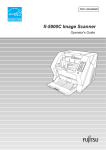
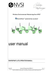
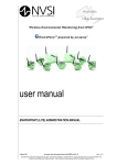
MEDICAL POWER WHEELCHAIR Owner’s Manual ATTENTION Please read your owner’s manual before driving your power wheelchair. UL8-W VENICE ~0~ CONTENTS INTRODUCTION page 3 FEATURE GUIDE page 3 EMI WARNING page 4 – 5 SAFETY INSTRUCTIONS page 6 – 7 PREPARATION FOR USE page 8 PROGRAMMABLE CONTROLLER page 8 ADJUSTMENT PROCEDUERS page 9 – 10 OPERATION INSTRUCTIONS page 11 – 12 DISASSEMBLY & ASSEMBLY INSTRUCTION page 13 EXTRA GUIDELINES IN THE CONTROL OF YOUR POWERCHAIR page 14 BATTERIES & BATTERY CHARGING page 15 – 16 MAINTENANCE page 17 TROUBLE SHOOTING page 18 – 19 WARRANTY TERMS & CONDITIONS page 20 - 21 SPECIFICATION page 22 DISCLAIMER page 23 ~2~ INTRODUCTION Congratulations on receiving the Shoprider Powerchair. This Powerchair is the ultimate combination of style and comfort. The short wheelbase allows easy maneuverability within the smallest spaces both indoors and outdoors. The rear drive wheels and electromagnetic brakes provide a safe and comfortable ride. This manual contains important information regarding the safe use of the Powerchair. P le a se re a d it ca re f u lly b e f o re u sing t h e P o we rch a ir a n d m a ke su re you understand all the instructions. Warning! Please make sure that you are physically fit to operate this unit. Consult your dealer/doctor for advice. FEATURE GUIDE (1) (2) (3) (4) (5) (6) (7) (8) (9) Captain Seat Joystick Controller Charging Port Armrest Safety Belt Rear Drive Wheel Front Caster Footrest Chassis Charger Port (2) (1) (4) (3) (5) (9) (8) ~3~ (7) (6) EMI WARNING ELECTROMAGNETIC INTERFERENCE (EMI) FROM RADIO WAVE SOURCES Medical Power Wheelchairs (Hereinafter referred to as “Powerchair”) may be susceptible to electromagnetic interference (EMI), which is a kind of interfering electromagnetic energy (EM) emitted from sources such as radio stations, TV stations, amateur radio (HAM) transmitters, two-way radio, and cellular phones. The interference (from radio wave sources) can cause the Powerchair to release its brakes, move by itself, or move in unintended directions. This can also permanently damage the Powerchair’s control system. The sources of radiated EMI can be broadly classified into three types: 1. Hand-held portable transceivers (transmitters-receivers) with the antenna mounted directly on the transmitting unit. Examples include: citizens band (CB) radios, “walkie talkie”, security, fire and police transceivers, cellular telephones, and other personal communication devices. NOTE! Some cellular telephones and similar devices transmit signals while they are ON, even when not being used. 2. Medium-Range mobile transceivers, such as those used in police cars, fire trucks, ambulances, and taxis. These usually have the antenna mounted on the outside of the vehicle. 3. Long-range transmitters and transceivers, such as commercial broadcast transmitters (radio and TV broadcast antenna towers) and amateur (HAM) radios. NOTE! Other types of hand-held devices, such as cordless phones, laptop computers, AM/FM radios, TV sets, CD players, and cassette players, and small appliances, such as electric shavers and hair dryers, so far as we know, a r e n o t l i k e l y t o c a u s e p r o b l e m s t o t h e P o w e r c h a i r. ~4~ EMI WARNING POWERCHAIR ELECTROMAGNETIC INTERFERENCE (EMI) Because EM energy rapidly becomes more intense as one moves closer to the transmitting antenna (source), the EM fields from hand -held radio sources (transceivers) are of special concern. It is possible to unintentionally bring high levels of EM energy very close to the Powerchair’s control system while using these devices. This can affect Powerchair movement and braking. Therefore, the warnings listed below are recommended to prevent possible interference with the control system of the Powerchair. WARNINGS 1. Do not operate hand-held transceivers (transmitters-receivers), such as citizens band (CB) radios, or turn ON personal communication devices, such as cellular phones, while the Powerchair is turned ON. 2. Be aware of nearby transmitters, such as radio or TV stations, and try to avoid close contact. 3. If unintended movement or brake release occurs, turn the Powerchair OFF as soon as it is safe. 4. Be aware that adding accessories or components, or modifying the Powerchair, may make it more susceptible to EMI. NOTE! There is no easy way to evaluate the overall immunity of the Powerchair. 5. Report all incidents of unintended movement or braking to the P o w e r c h a i r provider, and note whether there are sources of EMI nearby. ~5~ SAFETY INSTRUCTIONS Please use your Powerchair often and let it expand your horizons. The more mobility your Powerchair brings, the happier you will be! But, with all things, observing a few rules will ensure safe maneuvering. So please… (1) Do not drive the Powerchair without reading this instruction manual. (2) Do not use the joystick in an erratic manner when going up or down an incline. (3) Do not carry passengers or exceed the maximum user weight (Table 2). (4) Do not turn off the joystick controller by switching the On / Off Button when moving at speed. This will bring the electromagnetic brakes on immediately a n d c ou l d c aus e d am a ge t o t h e j o ys t i c k c o n t r o l l e r. (5) Do not drive over uneven or soft terrain. (6) Do not mount or dismount the Powerchair unless the electromagnetic brakes are engaged and the joystick controller is off. (7) Do not attempt to drive over curbs greater than 20mm in height. Doing so could cause your Powerchair to turn over, causing personal injury or damage to the Electric Wheelchair. For curbs less than 20mm, always approach them at a low speed (8) Do not operate the Powerchair if the unit is in freewheel mode. (9) Do not use on the road, except when crossing between sidewalks. (10) Do not sit on the Powerchair when in a vehicle, but transfer to a vehicle seat. (11) Do not exceed any grade over 6 degrees (10%). (12) Always stop fully before changing forward or reverse direction. (13) Always engage a slow speed when going down gradients (move the joystick slowly towards center position to reduce the speed). (14) Always approach and climb over curbs at slow speed. (15) Always use the safety belt. (16) Always keep feet on the footrest while driving. (17) Always make sure the batteries are fully charged before setting out on a journey. (18) Always make sure the Allen bolt, hex screws and nuts of the seat adaptor and seat post are securely tightened before driving the Powerchair. (19) Always charge the Powerchair in a well ventilated area. (20) Whenever a center bolt of the wheel assembly has been loosened, please replace with a specified new bolt from authorized providers and secure with a torque of 240 ± 5 kg-cm together with Loc-tite 271 adhesive (or equivalent). ~6~ SAFETY INSTRUCTIONS (21) When proceeding up any incline, please move the seat to the most forward position or if you have the deluxe seat, make sure that it is in the 90 degree (upright) position. (22) Do not adjust the programmer or modify the controller and cables without prior written approval from the manufacturer. Otherwise injury and/or damage to the Powerchair or surrounding property may occur. (23) Do not modify any parts on the unit without manufacturer’s written approval, or your warranty will be voided and you will be responsible for the modification. (24) Switch power off to the unit whilst not in use or before charging, removing and installing batteries, Otherwise injury and or damage could occur to the unit or surrounding property. (25) Charge the batteries before using and charge batteries daily after use. (26) Battery cables must be securely fastened onto battery terminals by the authorised dealer before using the unit. Batteries must be tied down correctly and securely. (27) Driver weight may exceed the weight of the unit ,Use caution and reduce speed when turning. (28) Avoid using the powerchair in wet conditions. (29) The chassis cover must be properly adjusted. The Velcro on the underside of the shroud should be aligned with the Velcro attached to the support brackets on the base of the unit. Make sure that the circuit breaker is properly aligned with the slot in the shroud to avoid any hindrance to the circuit breaker’s operation and use. (30) Do not use the Powerchair as a seat in any vehicle. (31) Always use low speed on downhill. (32) Do not operate over railway tracks. (33) Ensure the powerchair is serviced by an authorised Shoprider dealer every 12 months to ensure it remains in safe working order failure to do so may cause catastrophic failure with possible injury and damage to surrounding property Remember! Give consideration to pedestrians whenever using the Powerchair. You a r e a m o tor i s e d pe de s t r i a n a nd m us t obs e r ve a l l r ul e s a nd regulations of other pedestrians wherever possible. ~7~ INDICATION LABEL PREPARATION FOR LOCATION USE The Powerchair has many features designed to give the user maximum comfort. Adjustments can be made to the following parts of the Powerchair: (1) Armrests can be set at different angles. (2) Arms can be adjusted in height. (3) Arms can be adjusted in width. (4) Joystick controller can be fitted for either right or left hand use (no tools required). (5) Seat supporting post with hex head bolt & nyloc nut can be adjusted in height. Adjustments should be carried out by a provider/attendant while the user is seated in the Powerchair with the Powerchair turned off (the seat height adjustment is made when the user is not on the seat). NOTE! Before using the Powerchair for the first time, be sure the batteries have been connected. Charge the Powerchair for at least 6-8 hours prior to first time use. Please note the powerchair will charge much more quickly after the first charge PROGRAMMABLE CONTROLLER Shoprider Powerchair has a programmable controller. For more information regarding the programming parameters for the programmable Powerchair controller please contact your provider. ~8~ ADJUSTMENT PROCEDURES ARM ADJUSTMENTS (Fig.2) ANGLE Pull up on the end of the armrests and they will flip back up allowing easy transfer in and out of the seat. Under the armrest, there is a bolt and lock nut (1) that can be adjusted up or down to change the angle of the armrest. (3) (1) (2) Fig. 2 LENGTH (Adjustable Controller Bracket) Located under the armrest controller bracket is a hand knob (2). By turning counter-clockwise to release, the controller bracket can be extended and reset in position by re-tightening the hand knob. HEIGHT The vertical square tube connected with the armrest can be reset to the desired position by re-tightening the hand knob (3) for armrest height adjustment. WIDTH Beneath the rear of the seat there are two hand knobs, one on each side. Release the hand knob and slide each arm assembly outward. Re-tighten the hand knob when in the desired position. FOOTREST ADJUSTMENTS (Fig.3) Length (A) Pull out connecting pin from the first hole in the footrest slide tube. Slide out the footrest tube and refit the connecting pin in the appropriate hole when the required length is reached. Height (B) Pull out the connecting pin located at the back of the footrest slide tube and position the footrest at the required height. Three heights are available. Refit the connecting pin in the appropriate hole and make sure the connecting pin protrudes through the other side of the tube and is secure. ~9~ ADJUSTMENT PROCEDURES JOYSTICK CONVERSION (right to left or left to right) Loosen the hand knob [Fig.2 (3)] and remove the entire armrest assembly with the joystick attached. Place the armrest assembly on the desired side. Reset in position by re-tightening the hand knobs to complete joystick conversion. SEAT HEIGHT ADJUSTMENTS (Fig.4) Disconnect the power cord coming from the joystick/controller at the back of the Powerchair by pressing on the latch with your left hand and firmly pulling the cable plug with your right hand. Remove the seat by releasing the tightening lever. The seat supporting post under the seat has two height adjustment holes. The height of the seat can be adjusted by tightening the Hex Head Bolt and Nyloc Nut in any one of the two holes. This also secures the seat supporting post to the power base. Make sure that all connections are tightened before operating the Powerchair. Seat Supporting Post Tightening Lever Nyloc Nut Hex Head Bolt Fig. 4 ~10~ OPERATION INSTRUCTIONS JOYSTICK CONTROLLER (nVSI) OVERVIEW (Fig. 5) 8 2 5 1 7 4 3 6 Fig. 5 On / Off Button (1) This button turns the joystick controller (hereinafter referred to as nVSI) on and off. Do not use this button to stop the Powerchair, except in an emergency. Battery Gauge (2) The battery gauge shows you that the Powerchair is switched on. It also indicates the operating status of the wheelchair. Additionally, any fault in the Powerchairs electrical system is also indicated by this display. Refer to Table 1 for more details. Maximum Speed Indicator (3) This is a 5-segment display, which indicates the maximum speed setting selected. Horn Button (4) This button operates the Powerchairs horn. Speed Decrease Button (5) This button decreases the maximum speed. Speed Increase Button (6) This button increases the maximum speed. Joystick (7) This controls the speed and direction of the Powerchair. Push the joystick in the direction you want to go. The further you push it, the faster the speed will be. Releasing the joystick will automatically engage brakes and stop the Powerchair. Charger & Programmer Port (8) Only plug into this port with the charger that was supplied by factory. This port should not be used as a power supply for any other electrical devices. Connection of other electrical devices may damage the controller or affect the E.M.C performance of the Powerchair. ~11~ OPERATION INSTRUCTIONS GETTING READY TO DRIVE STEP 1 Press the On / Off Button, then the joystick will turn on after the Battery Gauge blinks for about a second. STEP 2 Press the Speed Increase / Decrease Button to set up a suitable level that you can maneuver the Powerchair easily. NOTE! The Powerchair will not move and the Battery Gauge will blink if you push the joystick before or right after you turn the joystick on. To restore the normal operating status, you have to release the joystick immediately back to its center position. If you do not release the joystick within five seconds, the Battery Gauge will flash rapidly. The Powerchair must be powered off and then turned back on again. STEP 3 Push the joystick to control the speed and direction of the Powerchair. NOTE! Choose an area with plenty of space to ride the Powerchair. Select the low level of the maximum speed setting until you are familiar with the controls. In a short time you will be in total control and can then increase the speed in steps. STEP 4 Release the joystick whenever you want to stop the Powerchair. ENGAGED / DISENGAGED MODE (Fig. 6) In the event of a fault or battery failure, the electromagnetic brakes can be disengaged allowing the Powerchair to be pushed. The levers should be switched to the freewheel position according to the indication labels to set the Powerchair to the Engaged / Disengaged Mode. NOTE! Do not use or sit on the Powerchair when either of the brakes is disengaged, or the joystick will not operate normally. Drive Mode (Engaged) (Disengaged) Free-wheel Mode Fig. 6 ~12~ DISASSEMBLY & ASSEMBLY INSTRUCTIONS DISASSEMBLY PROCEDURES (Fig. 7) WARNING! We advise caution when disassembling and lifting items. You must ensure that the person undertaking these actions is able to handle the weight. STEP 1 Ensure that the area in which the Powerchair is to be dismantled is spacious enough to accommodate all the components. STEP 2 The arms may removed to make the seat lighter to lift. Under the rear of the seat you will find tow “hand knobs”. Release both by turning anti-clockwise and slide out arms from each side. STEP 3 Fold seatback forward STEP 4 Disconnect the power cord coming from the joystick/controller at the back of the Powerchair by pressing on the latch with your left hand and firmly pulling the cable plug with your right hand. STEP 5 Release the black tightening lever underneath the seat. Stand behind the seat and while holding on with both hands lift straight up until the seat is released from the seat post. STEP 6 Hold onto the seat post with one hand. With your other hand pull the yellow release lever to release and separate the main body from the transaxle (rear portion) on the Powerchair. To reassemble the Powerchair, reverse the procedures described above. (2) (1) (3) Fig. 7 ~13~ EXTRA GUIDELINES IN THE CONTROL OF YOUR POWERCHAIR Ramps The stability of your Powerchair is governed by several factors such as the seating position, the angle of the slope and your height and weight. When approaching an incline, do so directly and not at an angle and where ever possible avoid making turns. When going down a ramp or slope keep the speed settings to slow. This will ensure there is a safe controlled descent. When the thumb levers are released the Powerchair will slowly stop. Safe Climbing Angle Always follow the guidelines of the safe climbing angle as shown in figure 8. Failure to observe the safe climbing angle may result in Injury to the user or damage to the unit. Caution - Do not turn off the main switch key while the unit is in motion Grass and Gravel Please follow the guidelines given previously and your Powerchair will perform admirably over many surfaces. Avoid long grass, loose gravel and sand. NOTE: You should not operate your Powerchair in wet weather or on wet surfaces. This may cause the motor to short out or cause other irreversible damage. NOTE: To preserve battery charge, your Powerchair may go into sleep mode after being idle for a few minutes. To remove from sleep mode, turn the power off and back on again. ‧ (Single user) Fig. 8 ~14~ BATTERIES & BATTERY CHARGING BATTERY CHARGING (UNITS EQUIPPED WITH OFF-BOARD CHARGER) Familiarise yourself with the safety information below prior to using the battery charger. SAFETY INFORMATION 1. Read the battery charger instructions in this manual and in the manual supplied with the charger prior to charging the batteries. 2. Do not remove the grounding prong from the plug. Removal of the grounding prong could result in an electrical hazard. 3. Only plug the charger into a 3-pronged electrical outlet, or an approved 3-pronged adapter for use with a 2 pronged electrical outlet. 4. Do not turn the charger on before the cord is correctly connected to the powerchair, failure to do so may cause personal injury or damage to the charger or powerchair. 5. Do not use an extension cord to plug in the charger. 6. Do not leave the charger plugged into the charger port if the charger is not charging the unit. 7. Use only the off-board charger supplied with this unit. The battery pack requires a very specific charger to ensure full charge and extended life Never use an automotive type battery charger. Contact your supplier if a replacement off-board charger is needed. 8. Inspect the battery charger, wiring and connections for damage prior to each use. 9. Do not open the battery charger case. 10. The battery charger is supplied with cooling slots. Do not insert objects through the slots. 11. Make sure that the charger is not in contact with flammable materials at any time. 12. The off-board charger is for indoor use only. 13. Explosive gases may be generated while charging the batteries. Keep the power chair and battery charger away from sources of ignition such as flames or sparks and provide adequate ventilation when charging the batteries. 14. Do not allow children to play near the power chair while the batteries are charging. It is also recommended that the batteries not be charged while the power chair is occupied. ~15~ BATTERIES & BATTERY CHARGING CHARGING INSTRUCTIONS 1. Connect the charger to the charging port at the front of the nVSI joystick (item 8 in Fig. 5) or the Chassis charger port (item 9 in figure 5)"Ensure it is Not turned on" Damage to the circuitry may occur 2. Plug the charger into the wall outlet. Now Turn it On at the wall 3. The charging process will start automatically. CHARGER INDICATION LIGHTS The 2 Amp off board battery charger has a status indicator which tells you when your battery pack is fully charged, there are three possible indications: 1. OFF = AC Input Power not connected / fault 2. RED = Charging 3. GREEN = Fully charged or DC Battery not connected Please refer to the above LED indicator description based on charging status of your charger. BATTERY INFORMATION 1. The Venice Powerchair is fitted with one PHET phosphate based Lithium-Iron 24 volt 10amp battery pack. -This pack has no serviceable parts - Virtually zero maintenance over the service life of the battery - Lightweight , high performance - Outstanding cycling ability . Based on different usage and the way of using it can go from 500 up over 200 cycles. - No Battery memory - Very quick charge time 2. Fully recharge new battery prior to initial use. 3. It is recommended that the batteries be charged for 6-8hours after daily use. 4. If the power chair is used infrequently (Once a week or less) the batteries will need to be charged once a week for 2-4 hours. 5. Do not charge the batteries for more than 24 hours at a charging cycle. 6. If you do not plan on using your power chair for an extended period it is recommended that you fully charge the batteries and then disconnect the battery harness prior to storage. Store the power chair in a warm dry environment. Never store the batteries where extreme temperatures are possible. Never attempt to charge a frozen battery. Warning! ‧ Always wear eye protection when working near batteries. ‧ Always keep battery terminals and clamps clean and free of corrosion. ‧ Never alter battery wiring or battery box. ‧ Never allow tools to make contact across terminals. ‧ .Do not smoke or use open flames when battery box lid is open. Only use batteries recommended by the manufacturer as replacement ! ~16~ MAINTENANCE Tyres Since your tyres are flat free tires, there is no need to ever worry about tire air pressure. General Maintenance and Lubrication Ensure the powerchair is serviced by an authorised Shoprider dealer every 12 months to ensure it remains in safe working order failure to do so may cause catastrophic failure with possible injury and damage to surrounding property Inspection for loose wheel bolts, seat and arm tightening bolts, and other nuts and bolts is recommended on a regular basis. Most lubricated components on the Powerchair are designed to be maintenance free and are sealed. Therefore lubrication is not required for these components. However, the driving axles and seat post should always have a very light coat of multipurpose grease. DO NOT USE TOO MUCH GREASE! Drips may stain or damage carpets, furnishings, etc. It is recommended that the driving axles (inside the drive wheel assembly) be checked and cleaned occasionally for hair and debris build-up, which will hinder the performance of the unit. Check the batteries on a regular basis. For extended battery life, it is highly recommended that the batteries be fully charged after each use. If the batteries are weak, severely discharged or old, a variety of problems may occur with the unit including charging problems, reduced speed, loss of range, and others. Please contact your local SHOPRIDER® provider for battery replacement. Cleaning Do not wash the powerchair with a hose If the unit requires cleaning us a damp sponge with a mild solution of detergent to wipe down the covers. Do not soak the unit as damage to the electrical system may occur. If the seat requires cleaning us a mild solution of detergent and damp sponge to clean the required area's Keep all moisture away from the hand controller at all times - if this part gets moisture inside it will lead to a new replacement part being required. ~17~ TROUBLE SHOOTING If a system trip occurs, you can find out what has happened by counting the number of flashes of the battery gauge. Below is a list of self-help actions. Try to use this list before you contact your provider. Go to the number in the list which matches the number of flashes of the battery gauge and follow the instructions. If the problem persists after you made the checks described above contact you authorized dealer. Table 1 BATTERY GAUGE POSSIBLE FAULT 1 Flash The battery needs charging or there is a bad connection to the battery. Check the connections to the battery. If the connections are good, try charging the battery. 2 Flashes The left hand motor has a bad connection. Check the connections to the left hand motor. 3 Flashes The left hand motor has a short circuit to a battery connection. Contact your authorized dealer. 4 Flashes The right hand motor has a bad connection. Check the connections to the right hand motor. 5 Flashes The right hand motor has a short circuit to a battery connection. Contact your authorized dealer. 7 Flashes A joystick fault is indicated. Make sure that the joystick is in the center position before switching on the controller. 8 Flashes A controller fault is indicated. Make sure that all connections are secure. 9 Flashes The parking brakes have a bad connection. Check the parking brake and motor connections. Make sure the controller connections are secure. 10 Flashes An excessive voltage has been applied to the controller. This is usually caused by a poor battery connection. Check the battery connections. ~18~ TROUBLE SHOOTING LOCKING / UNLOCKING THE POWERCHAIR The nVSI controller can be locked to prevent unauthorised use. The locking method is via a sequence of key presses and joystick movements, as detailed below. To lock the Powerchair: While the controller is switched on, depress and hold the on/off button. After 1 second the controller will bleep. Now release the on/off button. Deflect the joystick forwards until the controller bleeps. Deflect the joystick in reverse until the controller bleeps. Release the joystick, there will be a long bleep. The wheelchair is now locked. To unlock the Powerchair: Use the on/off button to switch the controller on. The maximum speed indicator will be rippling up and down. Deflect the joystick forward until the control bleeps. Deflect the joystick in reverse until the controller bleeps. Release the joystick, there will be a long bleep. The Powerchair is now unlocked. ~19~ WARRANTY TERMS & CONDITIONS Warranty Terms & Conditions The Warranty Terms and Conditions noted below provide your Shoprider® scooter with excellent coverage against possible defective parts or possible faulty workmanship. If at anytime you have a warranty issue YOU MUST contact the selling Shoprider® dealer as they are required to undertake the diagnosis and labour content of the warranty. Shoprider® will as noted below supply spare parts as required as part of this agreement. Structural Frame – 3 Years Shoprider Australia warrants that the frame will be free from defects under normal use, for a period of three (3) years from the date of purchase by the original customer. Shoprider Australia will repair or replace, at our option free of charge any part found on examination by Shoprider Australia to be defective in material and or workmanship within the warranty period. All parts claimed under warrant must be returned to Shoprider Australia in their present condition. Only an authorised “Warranty Dealer” of Shoprider Australia can undertake warranty work. Always contact the selling Shoprider® dealer to arrange all work and assess if warranty applies. Drive Train Assembly – 18 months Shoprider Australia warrants that the drive train Assembly will be free from defects under normal use, for a period of eighteen (18) months from the date of purchase by the original customer. Shoprider Australia will repair or replace, at our option free of charge any part found on examination by Shoprider Australia to be defective in material and or workmanship within the warranty period. All parts claimed under warrant must be returned to Shoprider Australia in their present condition. Only an authorised “Warranty Dealer” of Shoprider Australia can undertake warranty work. Always contact the selling Shoprider® dealer to arrange all work and assess if warranty applies. Drive Train Components include Transaxle, Motor and Magnetic Brake only ~20~ Warranty Terms & Conditions continued Other Parts – 12 months Shoprider Australia warrants that the other parts will be free from defects under normal use, for a period of eighteen (12) months from the date of purchase by the original customer. All parts claimed under warrant must be returned to Shoprider Australia in their present condition. Only an authorised “Warranty Dealer” of Shoprider Australia can undertake warranty work. Always contact the selling Shoprider® dealer to arrange all work and assess if warranty applies. Exclusions 1. All transportation cost associated with the submission and return of the repair or replacement under warranty (as determined by Shoprider Australia) are the responsibility of the original customer. 2. Normal wear items are not covered under warranty. These items include such items as brushes, tyres, tubes, brake pads, upholstery, seating and armrests. 3. Damage caused by - Excessive, abusive, misuse, negligence, accident or water - Improper maintenance, maintenance carried out by a non approved “Warranty Dealer” - Improper operation & storage - Any commercial use what so ever 4. Where an authorised dealer has not lodged all required documentation at the appropriate time, the warranty is Void 5. All warranties provided do not extend to purchasers of used or secondhand equipment (Warranty’s are not transferable) Please Note Our goods come with guarantees that cannot be excluded under the Australian Consumer Law. You are entitled to a replacement part for a major failure and for compensation for any other reasonable foreseeable loss or damage. You are entitled to have the goods repaired or replaced if the goods fail to be of acceptable quality and failure does not amount to a major failure NOTE: In the event of a warranty issue, Always contact your selling Shoprider® dealer who will arrange any work and return any faulty parts. Parts will be assessed and replaced within 3-5 working days. ~21~ SPECIFICATION Table 2 ITEM UNIT UL8-W Overall Length1 MM 870 Overall Width MM 580 Overall Height MM 851 Battery Capacity V_Ah x Pcs 24V/10Ah x 1 Total Weight (w/ Batteries) KG 41.8 Heaviest Part (Seat with hand controller) KG 16.4 Safe Climbing Angle °(%) 6(10) Suggested User Weight (on level surface) KG 113KG Maximum Speed2 kmph 5-6 Range3 (Per charge w/ standard battery) KM 12-14 Charger Type Off Board 24V, 2A ® All specifications are subject to change without prior notice. SHOPRIDER reserves the rights of any changes on the unit. 1. Includes the anti-tip wheel. 2. Driver weight may exceed weight of the unit, so speed must be reduced when turning. 3. The actual driving range varies with the factors shown below. a) the weight of occupant b) battery conditions c) type of charger d) ambient temperature e) the way of driving f) terrain g) the wind speed h) etc. ~22~ DISCLAIMER Congratulations on your purchase of the Shoprider® Powerchair This Powerchair is not intended to be used by individuals with physical limitations that could prevent the user from operating the Powerchair safely. Shoprider® disclaims all responsibility for any personal injury or property damage, which may occur as a result of improper or unsafe use of its products. The preceding guidance is intended to assist you in the safe operation of this Powerchair. If you should have any questions about the correct operation of the Scooter, please contact your authorised Shoprider® provider. Please complete the information below for future reference Shoprider Selling Dealer - _________________________________ Scooter Model Number - _________________________________ Scooter Serial Number - _________________________________ Date of Purchase - _________________________________ ATTENTION: This owner's manual is printed based on the latest specifications and product information available at the time of publication. SHOPRIDER® reserves the right to make changes as they become necessary. Any changes to the SHOPRIDER® range may cause slight variations between the illustrations and explanations in this manual and the scooter model that was purchased. Where possible a newer version of this manual may be available on our website www.shoprider.com.au SHOPRIDER Australia Pty Ltd 1 Business Way Malaga Western Australia 6090 www.shoprider.com.au P/N VENICE USER MANUAL ~23~ . ~24~