1
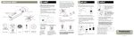
LM5 GENERAL IDENTIFICATION - Power on/off Select once to turn on. Hold down for 2 seconds to power off, release when “Goodbye” message is displayed. Also, select at any time to return to beginning of menu functions “home”. - Menu button Pages through complete menu options. - Control keys The two buttons on the right are used to change any parameter that appears in the display. In the normal operation mode, these two buttons will change the desired slope. The slope is limited to ±25.0%. - Flip button The slope can quickly be changed from right to left, or front to back, by pushing the “Flip” button. The numeric value of the slope does not change, but the direction does. If the display showed “←20.0%”, pushing the “Flip” button will change it to “20.0%→”. LM5 Overview The LM5 can be operated as a standalone instrument. Complete with 4 alkaline “AA” batteries the LM5 will operate on full power for at least 3 days. The LCD panel back light does go out after 20 seconds when not in use in order to conserve energy. If using the LM5 with an external sensor it must be connected to an external battery. Note: The LM5 is not programmed for auto shut-off. It is recommended user turn off the unit when not in use. The LM5 is also expandable to include a remote sensor. This sensor can be installed on moving parts such as blades, buckets and forks etc. depending on the application. The Menu will change to “EXT” when cable is connected. Menu Options 0.1 % INT 3.4% 100% When you first power up the LM5, the display will briefly show the product version. Then the following; Desired grade selection (top left) Real-time grade (top right) Internal vial (INT) or External Sensor (EXT) and battery percentage (if internal battery is being used) INT Selecting the Menu button will allow the user to scroll thru the various functions and features of the LM-5. Any changes made to the menu items will be saved automatically when you scroll thru to the next menu item Back Light Timer Enable Next The first menus item is for selecting the backlight configuration. Select the Flip button to enable or disable the backlight option. *Note: Battery life for time enabled is rated for 200 hours and disabled 12 hours of battery life. Select Next for following menu INT Horn Using either arrow keys you can turn the Horn option on or off. Select Next for following menu INT Alarm Grade OFF Next dead band 1.0 % INT Control axis Cross INT Next If horn is enabled the dead band grade settings can be changed. Alarm will sound when you go past the dialed in grade plus this offset. (ex. If grade setting is set at 0% and dead band is set at 1.0% the alarm will sound at any grade +1% and at any grade less than -1% slope) This menu allows the user to indicate which sensor orientation to use for their machine. There is 2 options either Cross rotation (left and right) or Fwd/Back (front and back). Zero Cal .1 4.1% Next Fast - - - I - - - - - - Slow Filtering Next English Next LATEC Instr. 519235-4585 Inc Next This screen is required to calibrate the LM5 to the terrain slope your equipment is situated on. This is described further under the calibration part of the manual. The LM-5 is designed with a fast response time. This fast response also reflects machine acceleration. Either vibrations or accelerations can cause erratic grade control. To reduce these false signals, it will be necessary to ‘slow down’ the sensor to some degree. Select the fastest filtering level that produces stable machine control. This is the language menu. By selecting the up arrow you have the option to change to French language. Information splash service screen. INT Initial Set-up Screen By selecting the power button and up arrow together the following menus are displayed. Sensor 6.7% Emulation 4.9% INT Sensor 1 Forward 16.7% Next INT Back Light Default INT 150 Next G o o d b y e! The left number value shows the left/right slope to 0 grade ratio and the right value displays front/back percentage. This screen verifies that the vial has valid readings in regards to its zero position This menu allows for orientation of the sensor in regards to the machines forward travel. When using an external sensor enter the number on the top of the sensor which is pointing in the forward travel of the machine. For internal sensors the configuration should be set to 1 - Forward. The menu defaults back to main screen after 15 seconds. This screen allows for backlight brightness. Select up or down arrows to change. Select Default for factory setting. This screen will change back to main menu after 15 second. Final menu screen. hold power off for 2 seconds to power off. Installation and Calibration The LM-5 has 2 options for calibration. Option 1 is used when the LM5 is being used as a stand alone unit with no external sensor. Option 2 is to be followed when an external sensor is being used. **The unit must be recalibrated every time the orientation of the sensor is changed (ex. Forward/back to left/right)** Option 1 – the Stand alone unit. The LM5 has an internal vial which gives the user grade readings from +25% to -25%. The control box must be mounted so it is perpendicular to the machines forward travel. The control box can be tilted to allow for easy viewing by the operator but this must be adjusted before calibration and cannot be re-adjusted, as this will affect the unit’s calibration. Control axis Cross INT Zero Cal .1 4.1% Zero Cal . 2 4.1% -Scroll thru the menu items to get to the Control axis screen This menu allows the user to indicate which sensor Next orientation to use for their machine. There is 2 options either Cross rotation (left and right) or Fwd/Back (front and back). -Press the next button to move to the Zero cal screen. -Lower the blade so it is resting on the ground. -Mark this position. Next -Press the up arrow to store this position. The screen should change to Zero Cal 2. -Turn the machine around 180˚ and rest the blade on the ground in the same location as marked previously. -Press the up arrow to store this position. Next -Your LM5 is now calibrated to your machine. Option 2 – the External sensor. The LM5 has an external sensor option to give the user direct blade feedback in contrast to the position of the machine itself. For the external sensor to be activated the unit must be connected to external power (+12 - +30vdc) and have the sensor cable attached to the sensor and control box. When the external sensor is connected the display will show ‘EXT’ in the bottom left corner in contrast to the ‘INT’ displayed for the internal sensor. Control box installation: To install the control box find an area in the cab which allows the users easy viewing of display and does not interfere with general use. Orientation of control box does not have an effect on calibration when using an external sensor. Sensor Installation: 1. Remove weldment bar from the Sensor Box using a 9/16” wrench 2. Clean off the surface where the Weldment bar will be welded, ensure the plate where the bar will be welded is flat and free of bumps. 3. Weld the bar onto the unit so that both holes are vertical. (The straighter the bar is installed the better). 4. Ensure the correct cable ends are at the control and sensor units. Carefully route the sensor cable so the blade can swivel without stretching the cable. Tie the cable with tie wraps(not included) so that the wire cannot be pinched. 5. Connect the sensor cable to the sensor box. With the sensor connected the calibration can now begin for the External sensor. External Sensor Calibration: -first enter the the initial set-up screen (see page 3) and enter the number on the top of the sensor which points Sensor 1 Forward to the forward direction of the machines travel. 16.7% Next Once the sensor is oriented properly, the blade can be calibrated. To calibrate the blade we must exit the initial set-up screen and enter the menu screen INT -Scroll thru the menu items to get to the Control axis screen This menu allows the user to indicate which sensor Control axis orientation to use for their machine. There is 2 options Cross Next either Cross rotation (left and right) or Fwd/Back (front and back). -Press the next button to move to the Zero cal screen. INT -Lower the blade so it is resting on the ground. Zero Cal .1 -Mark this position. -Press the up arrow to store this position. The screen 4.1% Next should change to Zero Cal 2. -Turn the machine around 180˚ and rest the blade on the ground in the same location as marked previously. Zero Cal . 2 -Press the up arrow to store this position. 4.1% Next -Your LM5 is now calibrated to your machine. LM5 Wiring: The external sensor comes complete with power and sensor cable. The sensor cable is 30’ and it has a power hook-up which extends 18’. The power wire has a 1 amp fuse in series to be attached to the machines battery. The pin outs for the control box to sensor cable is as follows: Control box Sensor box Description Pin 1 Pin 2 power (+12 – 30Vdc) Pin 2 Pin 4 Can high Pin 3 Pin 6 Can low Pin 4 Pin 8 machine ground