1
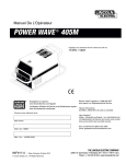
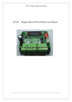
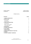
SELECTRONIC AUSTRALIA
SE30 OWNERS MANUAL
Contents:
Page
INTRODUCTION..............................................................................................................................2
WARRANTY CARD .........................................................................................................................2
INSTALLATION ...............................................................................................................................2
CONNECTION OF AC AND DC WIRING ......................................................................................3
OPERATION......................................................................................................................................5
LIQUID CRYSTAL DISPLAY..........................................................................................................5
READINGS ........................................................................................................................................5
SET PARAMETERS ..........................................................................................................................6
OVERLOAD SHUTDOWN AND ALARMS ..................................................................................7
HANDY HINT. ...................................................................................................................................8
FAULT FINDING ..............................................................................................................................9
SYSTEM MAINTENANCE............................................................................................................10
SE30 MAINTENANCE....................................................................................................................10
BATTERY MAINTENANCE..........................................................................................................10
SE30 ELECTRICAL SPECIFICATIONS.....................................................................................11
RADIO FREQUENCY INTERFERENCE....................................................................................12
APPENDIX A
DIAGNOSTICS .................................................................................................13
APPENDIX B
FLOW DIAGRAM FOR DISPLAYS AND SETTINGS................................14
APPENDIX C
FLOW DIAGRAM FOR DIAGNOSTICS......................................................14
WARNING........................................................................................................................................16
PRODUCT WARRANTY CONDITIONS ....................................................................................16
Rev 1
1
INTRODUCTION.
Thank you for your purchase of the Selectronic Sine wave inverter, model SE30.
Your SE30 is a state-of-the-art high performance TRUE SINE WAVE DC-AC Inverter.
Many hours of development time have been invested in the SE30 so that we can provide you with a
reliable high quality inverter. The output from your SE30 is as good as, if not better than mains power.
If looked after properly, the SE30 will give you many years of reliable service.
WARRANTY CARD
Before proceeding any further, it is extremely important that you complete your warranty card
NOW. This will enable us to immediately register your 5 year warranty period. By accurately
completing your warranty card, you will provide us with valuable information that will assist us in
keeping up with your alternative energy needs. Please take a few moments to fill in the warranty
card. Your efforts will be greatly appreciated.
INSTALLATION
The installation of your inverter is extremely
important. Failure to follow the recommended
installation instructions may void your warranty. If
in doubt, ask your supplier.
After unpacking, check for any damage which may
have occurred during transit. If there are any signs
of damage, contact your supplier immediately.
The Inverter must be installed in a dry, cool, dustfree environment.
300mm
SELECTRONIC SINE WAVE INVERTER
SE30
DC TO M AINS POWER
PROUDLY DESIGNED & MADE IN AUSTRALIA
200mm
Please leave at least 300mm clearance around the
sides and top of the Inverter and approximately
300mm
200mm at the rear as this will aid the natural
cooling of the Inverter. The air vents on the
underside of the SE30 also need to be kept clear of
obstructions.
Front
We suggest that you house your Inverter and other
power generating equipment in a purpose built shed remotely sited from the home, and as far away as
possible from any radio transmitters or receivers. Also make sure that the exhaust from your generator
or other sources of heat or fumes are kept well away from the SE30. SEIAA (Solar Energy Industries
Association Of Australia) installation guidelines must be followed.
You must have a suitable 24V DC battery bank which is maintained and operated to the battery
manufacturer’s recommendation. To ensure operation to SE30 specification, the battery bank should
have a minimum capacity of 700 ampere hours at the 100 hour discharge rate (ask your supplier if in
doubt). Smaller capacity batteries can be used but may result in degraded performance of the SE30
under heavy surge conditions.
2
A
SUPPLY
System Fuse
Battery
bank
INSTALLATION
N
To circuit breakers
for other circuits
Earths
Inverter
Rear
junction
Box
E.L.C.B.
main switch
Active
Earth
Neutral
(E.L.C.B.)
A
S1
GND
RFI Earth
As close as possible to
inverter.
Must be bonded to all
other earths
Earth Leakage
Circuit Breaker
S2
Power
N Circuits
E
Neutral Link
GND
Ground connection to
general mass of earth
All AC and DC wiring must
conform to relevant standards
* SYSTEM FUSE
A system fuse is an extremely important part of any power system, this fuse is designed to give one
point of complete disconnect in case of a serious fault. The fuse should have a sufficient rating so as not
to blow under heavy load conditions. Your inverter will normally be the biggest load in your system, if
this is the case a motor start fuse equal to or slightly higher than the maximum continuos current of the
inverter should be used.
If in any doubt see your supplier or installer.
CONNECTION OF AC AND DC WIRING
IMPORTANT: Before making any wiring connections, check that the circuit breaker on the front
panel is in the OFF position, i.e.; LEVER DOWN.
Your electrician should firstly connect the AC wiring via the three terminal rear junction box. Carefully
observe the correct connections. Please refer to the diagram overleaf.
BROWN
ACTIVE
(red dot, top connector)
GREEN/YELLOW EARTH
(E, centre connector)
BLUE
NEUTRAL (Bottom connector)
The lid of the junction box has knockouts to allow conduit entry. Make sure this connection is tight and
safe. Re fit junction box cover.
NOTE:
ALL AC WIRING MUST BE CARRIED OUT BY A LICENSED ELECTRICIAN
AND MUST CONFORM TO AS3000 WIRING REGULATIONS,
OR RELEVANT STANDARDS.
Verify that the circuit breaker on the front panel is in the OFF position, LEVER DOWN.
Now connect the battery cables.
RED
BATTERY POSITIVE (+)
BLACK BATTERY NEGATIVE (-)
These connections should be tight. If using nuts, bolts and washers, they should be stainless steel. At
this point re-check the connections before proceeding any further.
3
NOTE:
IF THE SE30 EMITS A PULSING BUZZER SOUND, THE BATTERY LEADS HAVE BEEN CONNECTED IN
REVERSE. IMMEDIATELY DISCONNECT THE LEADS AND RECONNECT WITH THE CORRECT
POLARITY. DO NOT, UNDER ANY CIRCUMSTANCES, TURN ON THE BREAKER WHEN THE BUZZER IS
PULSING AS PERMANENT DAMAGE TO THE SE30 WILL RESULT.
If all is well you can now switch the circuit breaker ON. If after two (2) attempts the circuit breaker
does not turn on, refer to FAULT FINDING section of this manual (see page 10).
4
OPERATION
When you first apply power, the SE30 will be in STANDBY mode. There will be a quiet pulsing
sound. The SE30 is now ready for use.
LIQUID CRYSTAL DISPLAY
The liquid crystal display and key pad on the front panel of the SE30 will provide you with vital
information about your power system , whilst allowing you to set a number of parameters within the
SE30.
READINGS
The SE30 has one STATUS and three READINGS displays. By pressing the 'NEXT DISPLAY' key on
the front panel, the screen information rotates through displays of Inverter Status, AC Volts, AC Amps
and Battery Volts.
STATUS
Status : STANDBY
Inverter : OFF
Status : CONT
Inverter : ON
Status : RESET
Inverter : OFF
The first screen will display the Status of the SE30. There are three status conditions: STANDBY,
CONT (continuous) and RESET, which are explained in more detail below.
When this screen is displayed, the Status can be changed by pressing the UP or DOWN keys. Each time
the UP key is pressed, the status will change from STANDBY to CONT to RESET and back to
STANDBY where as the DOWN key will change the Status in the reverse order.
The second line indicates whether the inverter is ON or OFF, i.e. if there is 240V available or not.
During pulsing, OFF is displayed on the second line, reverting to ON when a load is connected and the
inverter starts.
STANDBY mode means that the SE30 is producing pulses of power while waiting for an appliance
to be switched on. This is called the demand start because as soon as the appliance is switched on,
the SE30 will turn on and remain on until 10 seconds after the appliance is switched off. After this
time, the SE30 will return to pulsing or demand start mode waiting for another load.
This feature is extremely important as it conserves valuable battery power when no appliances are on.
The amount of power that the Inverter needs to “ start up” is adjustable, see page 6 for details.
CONT mode (CONTINUOUS) means that the Inverter will be on at all times regardless of the load.
This situation is useful if you have small loads such as a VCR or digital clock that requires 24 hour
power, or if loads are too small to be sensed in the STANDBY mode. The only disadvantage is that
when no appliances are operating, the SE30 will be drawing more power than it would in STANDBY
mode.
RESET mode electronically shuts down the inverter. When placed in this mode, any overload or
shutdown conditions are also reset. This situation will be explained in more detail in a later section.
5
AC VOLTS
AC Volts : 240V
- - - Readings - - -
This reading gives an approximate indication of the AC voltage produced
by the inverter. When set to 240V (see ‘Set Parameters’ page 6) , the AC
volts will read between 230V and 245V except under high load or low
battery conditions.
AC AMPS
AC Amps : 2.5A
- - - Readings - - -
The AC Amps reading shows the total current drawn from the AC output by
the appliances connected to the inverter. This reading is also handy for
knowing how much power a particular appliance draws.
BATTERY VOLTS
Batt Volts : 24.6V
- - - Readings - - -
Displays the DC Battery volts. This provides you with an indication of the
condition of your battery bank.
SET PARAMETERS
There are a number of parameters within the SE30 which can be changed via the front panel push
buttons to allow you to tailor the SE30 inverter to suit your system requirements. These are: Buzzer, DS
sense (Demand start sensitivity), Lo DC Volts, Lo DCV on, Hi DC Volts and AC Volts.
Set parameters are accessed by holding down the NEXT DISPLAY key for at least 1 second whilst in
any "Readings" display. The value of the parameter displayed can then be modified by pressing the UP
or DOWN keys.
Pressing the NEXT DISPLAY key will take you to the next parameter to be set. Pressing the NEXT
DISPLAY key after the last parameter is displayed will take you back to the "Readings" displays.
Please note: If DC power is disconnected from the inverter, the "parameters" which have been entered
will be saved and held in permanent memory. However these “parameters” are not saved until the
display is returned to “Readings”.
BUZZER
Buzzer : ON
[Set Parameters]
This display allows you to select whether the audio alarm will sound during
an overload or other alarm condition. Use the UP or DOWN keys toggle
between ON or OFF state. This will be set to ON when leaving the factory.
DS SENSE
DS Sense : 6W
[Set Parameters]
This sets the minimum load which will bring the SE30 ON when the
inverter Status is set to STANDBY mode in (demand start or pulsing). See
page 5. In most cases the default setting of 6W would be suitable. If there
is a load which the SE30 won't sense then reduce this value until the SE30
starts. Alternatively if there is a small load that keeps the SE30 ON, then
increase this value. You may need to try a few different settings to find the
most appropriate value for your installation. Use the UP or DOWN keys to
set
the
value.
6
LO DC VOLTS
Lo DC Volts : 20.0
[Set Parameters]
The SE30 will cut out and a message will be displayed if the battery
voltage falls below this setting for more than 10 seconds. The inverter will
restart if reset, or when the battery volts rise above the 'Lo DCV on' setting.
Use the UP or DOWN keys to change the value. This value is set to
20.0volts when leaving the factory.
LO DCV ON
Lo DCV on : 24.0
[Set Parameters]
The SE30 will restart after a Low Battery Volts cut out when the battery
volts rise above this setting. Use the UP or DOWN keys to change the
value. This value is set to 24volts when leaving the factory.
HI DC VOLTS
Hi DC Volts : 34.0
[Set Parameters]
When the battery volts exceeds this setting, the SE30 will cut out
instantaneously . Use the UP or DOWN keys to change the value. This
value is set to 34volts when leaving the factory.
AC OUTPUT VOLTS
AC Volts : 240V
[Set Parameters]
Allows the AC output voltage to be set in a range of 220V to 240V if an
output voltage other than 240V is required. Users outside Australia should
check with their system designer for the correct setting. Use the UP or
DOWN keys to change the value. This value is set to 240V when leaving
the factory..
OVERLOAD SHUTDOWN AND ALARMS
The SE30 has six alarm and overload conditions. These result from high or low battery volts, high AC
volts, AC output overload, transformer being too hot or heatsink too hot. If one of these conditions
occurs, a message will be displayed. If there is more than one alarm condition the display will alternate
between messages.
The alarm message will remain on the display until a key is pressed even if the alarm condition ends
(i.e. after a high voltage condition the battery volts comes back down again). This allows you to
determine the cause of the shutdown even if the inverter comes on again before you are able to read the
display. To reset the inverter after it has shutdown, simply press any key.
DC VOLTS HI
Hi DC Volts : 33.0
* * Press a Key * *
This message is displayed and the inverter shuts down if the battery voltage
rises above the Hi DC Volts setting. The inverter will automatically restart
when the battery voltage drops below this value. The present battery voltage
is also displayed.
7
DC VOLTS LO
Lo DC Volts : 19.5
* * Press a Key * *
This message is displayed and the inverter shuts down if the battery voltage
drops below the ‘Lo DC Volts’ setting for more than 10 seconds. The
inverter will automatically come on again when the battery voltage rises
above the ‘Lo DCV on’ voltage or if the inverter is manually reset (via the
STATUS display, see page 5). The present battery voltage is also displayed.
AC VOLTS HI
AC Volts Hi : 0
* * Press a Key * *
If a system fault causes the AC voltage to go too high, then this message is
displayed.
INVERTER O/L
Inverter O/L : 0
* * Press a Key * *
An AC current overload or a short circuit on the AC output will cause the
inverter to shut down and display this message. If the shutdown was due to
an overload, the SE30 will automatically reset after 1 minute or when a key
is pressed. If the shutdown was due to a short circuit, the SE30 will have to
be reset (via the STATUS display, see page 5) on the front panel.
TX TOO HOT
TX Too Hot : 122C
* * Press a Key * *
If the internal transformer reaches its maximum operating temperature, the
SE30 will shut down to protect the internal components. The SE30 will
restart again only when the temperature drops to a safe level. The present
temperature of the transformer is also displayed.
HS TOO HOT
HS Too Hot : 82C
* * Press a Key * *
If the black external heatsink reaches its maximum operating temperature,
the SE30 will shut down to protect itself. The SE30 will come on again only
when the temperature drops to a safe level. The present temperature of the
heatsink is also displayed.
HANDY HINT
It is very important that you become familiar with the functioning of your Inverter. Since most Inverters
are not within sight, it is not always easy to know what STATUS your inverter is in. An easy way to
determine this is to plug a small child's night light (neon type) into a power point which is easily visible,
or replace any power point with a neon indicator type. This will indicate the inverter's operation by
flashing when the inverter is pulsing and remaining on when the inverter is brought on by a load.
8
FAULT FINDING
1. INVERTER STAYS ON EVEN WHEN NO APPLIANCE IS BEING USED.
This can be a common problem known as a "phantom load", but can be easily overcome with the SE30.
Some appliances will need to be switched off at the power point as they may still represent a small load
despite being switched off at the appliance. Check again to make sure there are no appliances left on,
then sequentially switch off appliances at the wall and by watching your night light (as described in
“Handy Hint” on page 9) check to see if the SE30 returns to pulsing mode (after a 10 second delay).
Once you have found the offending appliance, adjust the sensitivity of the demand start up (see “Set
Parameters” on page 7 ) until the Inverter turns off. Once this is done re check that small loads will still
bring the Inverter on when required.
2. INVERTER WILL NOT COME ON WHEN SMALL APPLIANCE IS SWITCHED ON.
This means that your demand start sensitivity is set too high. With the appliance in question switched
on, adjust the demand start sensitivity (see "Set Parameters" section on page 7) until your SE30 turns
on.
3. INVERTER SHUTS DOWN DURING MIDDLE OF THE DAY AND COMES BACK ON
LATE AFTERNOON.
This is more than likely caused by high battery volts during peak charging times from solar panels.
To overcome this, adjust the high voltage cutout of your SE30 (see “Set Parameters” on page 7); the
maximum voltage allowable being 34 volts. If this is still not high enough you may have a problem
with either your batteries or your regulator. This could be potentially dangerous so we advise you to
consult your system designer immediately.
4. INVERTER SHUTS DOWN WITH LOW VOLTS.
If your SE30 has shut down because of low DC volts it could be due to the following:
(1) A sustained large load could be causing the battery volts to drop to a low enough point to cause the
SE30 to cut out. This is not normally a fault with the SE30 but could be due to the following:
(a) Battery bank is too small- consult your system designer.
(b) A bad connection between the batteries and inverter due to a loose or corroded terminal. In
this case, please refer to the maintenance section of this manual (on page 11.)
(c) One or more battery cells could be faulty - consult your installer.
(2) If your battery volts are below 24.0V with no loads connected, the batteries may require charging.
Use a hydrometer to check the specific gravity of each cell. Consult your battery manual for the
correct specific gravity (SG) readings.
5. INVERTER SHUTS DOWN DUE TO HS TOO HOT
This is likely under sustained heavy load conditions since the SE30 shuts down to protect its internal
components. If you believe that the load is not excessive, check around the Inverter case and heatsink
for obstructions to air flow as this will cause the Inverter to heat up much quicker and shut down sooner
than normal. Also check that the clearances around the SE30 are as specified in INSTALLATION on
page 2.
6. INVERTER PULSES SLOWER THAN NORMAL WHEN IN STANDBY
This means that the inverter has not been switched on for approximately 20 minutes and has gone into a
power saving mode, thus pulsing at about half the normal rate.
9
SYSTEM MAINTENANCE
To get the optimum performance from your SE30 power inverter, particularly under heavy appliance
loads, it is essential that the battery bank and the DC wiring are all in good condition. The small amount
of time spent on the below maintenance tasks will maximise the reliability of your system.
SE30 MAINTENANCE
Periodic maintenance of the SE30 inverter involves little more than checking for unobstructed
operation of the cooling fan, which is located at the rear of the inverter. Note that cooling air is drawn in
through vents underneath the inverter.
Suggested inverter maintenance should include:
1.
Check for unobstructed fan operation:
Clear away any dust or foreign matter from the fan grill using a soft bristled brush.
(Do not direct high pressure compressed air at the fan blades)
Note that the fan is designed to come on during heavy power demand.
2.
Check between fins of the heatsink and clean out any accumulated foreign objects, for example,
insect nests.
3.
Verify that the air flow beneath the chassis is not restricted.
BATTERY MAINTENANCE
IMPORTANT:
When working on batteries of such high capacity it is essential that you wear protective
clothing, some form of eye protection and rubber-soled work boots. Please regard your
batteries with a great deal of caution, and if in any doubt, entrust this work to your installer.
1.
Every week, carry out a thorough visual inspection of all battery wiring, taking particular note
of the condition of inter-connections between cells.
2.
Check that the stainless steel inter-connecting bolts are tight and have minimal corrosion. If
corrosion is evident, carefully follow the following procedure.
(a) Disconnect the system battery fuse before working on the battery bank.
(b) Unbolt the stainless steel bolts and nuts of any corroded connections and thoroughly clean
the joint with a wire brush or file, taking extreme care not to short circuit any battery cells
with any tools.
(d) Re-assemble and smear a small amount of Vaseline or similar grease over the surface of
the joint to slow down any future corrosion.
3.
Every month or as directed in your battery instruction manual, measure the specific gravity
(SG) of each cell using your hydrometer, to ensure that all cells are performing correctly. Any
serious imbalance should be reported to your system designer in case remedial action needs to
be taken.
10
SE30 ELECTRICAL SPECIFICATIONS
INVERTER TYPE
PWM Full bridge power stage, with true sine wave AC output.
DEMAND START SECTION
Type:
Pulsing AC
Minimum Load Power to start (User adjustable):3W to 20W
Maximum response time:
1 sec
Standby power from battery (Average):
66mA
BATTERY VOLTAGE RANGE
Low DC Volts Cutout
Low DC Volts Cut-in
High DC Volts Cutout
(Delayed, User Adjustable):
(Delayed, User Adjustable):
(Instantaneous, User Adjustable):
19-22V
22.2-26V
30-34V
TOTAL APPLIANCE RATING
Continuous:
30 Minute rating:
5 Minute rating:
1 Minute rating:
Surge rating:
At 25 °C
At 40 °C
2200W
3500W
4300W
5300W
6500W
2000W
3200W
INVERTER EFFICIENCY
Peak (at 500W):
No load power consumption (CONT mode):
93%
0.70A
MISCELLANEOUS SPECIFICATIONS
Output Frequency Accuracy:
Output Voltage Accuracy (0 - 2000W):
Total Harmonic Distortion (THD):
Operating temperature range:
Weight:
50Hz +/- 0.001%
240V +/- 4%
< 4%
-10ºC to 50ºC
22kg
DC Input is Electrically Isolated from AC Output.
Note: Through a policy of continued development, specifications are subject to change without notice.
The above specifications are based on unity power factor.
11
RADIO FREQUENCY INTERFERENCE
For many years, Radio Frequency Interference (RFI) has been an annoying problem for owners of
Inverters. RFI in a domestic situation may produce noise or interference on a radio or TV receiver.
Most of the problems with RFI in a Remote Area Power Supply (RAPS) installation involves AM radio
reception.
Considerable development time has resulted in a reduction of the RFI produced by the SE30 to a level
which complies with Australian Standard AS1044. Compliance to this standard means RFI is low, but
how well the inverter performs in a particular installation can vary. Below are some suggestions to help
reduce the effects of RFI in your installation.
It is recommended that the power system including the inverter is housed at least 15 metres from the
home.
Ensure a good earth stake is placed as close to the inverter as possible.
See “INSTALLATION” on page 2 for wiring.
Avoid running DC cables into the home, if at all possible. If this cannot be avoided, run DC and AC in
separate conduits separated by as much distance as practicable. All DC wiring should also be kept as
short as possible.
To further reduce the effects of RFI, it is important that your AM radio has good signal strength. This
will enable your radio to reject any noise being produced by your inverter, regulator, controllers or DC
lighting. If possible, try moving the radio around to improve the signal strength or use an external
aerial. Some of today's building materials such as steel roofs and foil insulation may form a barrier to
incoming radio signals. If an external aerial is required, it should be on the outside of the home,
mounted as high as practicable and as far from the battery shed as possible. Connection from the aerial
to the radio should be via a low loss coaxial cable.
PLEASE NOTE: This aerial must be an AM RADIO type; a TV aerial will not work.
If your inverter is to be installed in a Mobile Home or similar, try to keep your inverter at least 4 feet
away from your radio or audio equipment. The further the better.
12
APPENDIX A
DIAGNOSTICS
The "Diagnostics" is a special set of displays which give additional information about the SE30. These
are normally only used when advanced troubleshooting is undertaken. The "Diagnostics" section
displays the transformer and heatsink temperature, demand start current and software version
information.
"Diagnostics" is accessed by holding both UP and DOWN buttons together for more than 1 second
during the display of any "Readings" screen. The NEXT DISPLAY key takes you through the
"Diagnostics" displays, eventually returning to the "Readings" display.
TRANSFORMER TEMPERATURE
TX Temp : 75C
* * Diagnostics * *
This display is the operating temperature of the transformer inside the SE30
in degrees Celsius. Pressing NEXT DISPLAY button will take you to the
next display.
HEATSINK TEMPERATURE
HS Temp : 34C
* * Diagnostics * *
This displays the operating temperature of the heatsink. Pressing NEXT
DISPLAY button will take you to the next display.
DEMAND START CURRENT
D/S Current : 48
* * Diagnostics * *
This gives a reading of the value read by the demand start sense circuit and
can be useful during advanced demand start troubleshooting. Pressing
NEXT DISPLAY button will take you to the next display.
SOFTWARE VERSION
SELECTRONIC C
SE30 1.00 1997
This displays the revision of the software running your SE30. Please note
that this software is Copyright to SELECTRONIC AUSTRALIA P/L and it
is an offence to copy or duplicate any part of this program. This is the last
screen in the "Diagnostics" and pressing the NEXT DISPLAY key once
more will return you to the readings.
13
APPENDIX B
FLOW DIAGRAM FOR DISPLAYS AND SETTINGS
Power first
applied to unit
Hold
NEXT
DISPLAY
button for 1
second
Buzzer : ON
[Set Parameters]
Status : STANDBY
Inverter : OFF
NEXT
DISPLAY
NEXT
DISPLAY
AC Volts : 240V
- - - Readings - - -
DS Sense : 6W
[Set Parameters]
NEXT
DISPLAY
NEXT
DISPLAY
AC Amps : 2.5A
- - - Readings - - -
Lo DC Volts : 20.0
[Set Parameters]
NEXT
DISPLAY
NEXT
DISPLAY
Batt Volts : 24.6V
- - - Readings - - -
Lo DCV on : 24.0
[Set Parameters]
NEXT
DISPLAY
NEXT
DISPLAY
Hi DC Volts : 34.0
[Set Parameters]
NEXT
DISPLAY
AC Volts : 240V
[Set Parameters]
NEXT
DISPLAY
END SETTINGS
NEXT
DISPLAY
14
APPENDIX C
FLOW DIAGRAM FOR DIAGNOSTICS
Hold both
UP
and
DOWN
buttons for 1 second
TX Temp : 75C
* * Diagnostics * *
NEXT
DISPLAY
HS Temp : 34C
* * Diagnostics * *
NEXT
DISPLAY
D/S Current : 48
* * Diagnostics * *
NEXT
DISPLAY
SELECTRONIC C
SE30 1.00 1997
NEXT
DISPLAY
Returns to ‘READINGS’
15
WARNING
THE OUTPUT VOLTAGE FROM AN INVERTER IS JUST AS
LETHAL AS LANDLINE POWER.
It is therefore absolutely necessary for your safety to ensure that all Remote Area
power system installations meet and comply with the relevant provisions and
requirements of AS3000 wiring standards.
It is imperative that you ensure that only Electrical contractors are permitted to
install any AC wiring in your system.
PRODUCT WARRANTY CONDITIONS
Selectronic Australia Pty Ltd warrants your SE30 inverter to be free from defects
in materials and workmanship under normal use and service, for an initial period
of five (5) years.
This warranty is applicable only from the date of original purchase. All parts will
be replaced or repaired free of charge within this period. Travelling time for field
service personnel is not covered under this warranty. If no authorised field
service personnel are available, the unit shall be returned to one of the below
mentioned service centres, this must be done at the owners cost. There will be no
charge for the return of the inverter.
The provision of this warranty shall not apply if the unit has been subject to
misuse, neglect, act’s of God, accidental damage or has been used for a purpose
for which it is not designed.
Charges to the point of purchase and the cost of any repairs resulting from
damages occurring during this freighting will be borne by the owner. Any
alterations or repairs by unauthorised parties will void your warranty.
To ensure fast efficient handling of any warranty claims, please complete and
return your reply paid warranty card within 30 days from date of purchase.
If service is required, contact your supplier or return your inverter in its original
carton with proof of purchase to any of the following service centres.
Selectronic Australia
25 Holloway Drive
Bayswater
Victoria
3153
Australia
Ph: 03 9762 4822
Fax: 03 9762 9646
Burley TV Service
278 Edmondson Ave.
Austral
NSW 2171
Australia
Ph: 02 9606-0279
16
Reid Technology Ltd
3-5 Auburn Street
Takapuna
North Shore City
Auckland
NZ
Ph: 9 489-8100
Fax: 9 489-8585
RF Analysis
Harness Cask Road
Dorrigo
NSW 2453
Australia
Ph: 066 57 8003
Fax: 066 57 8002