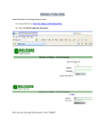
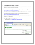
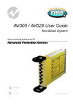
1
6R MATRIX User Guide Auxiliary, Trip & Supervision Relays relay monitoring systems pty ltd Advanced Protection Devices User Guide Test Manual 6R MATRIX User Guide About This Manual This User Guide covers all 6R MATRIX relays manufactured from May 2003. Earlier relays do not necessarily incorporate all the features described. Our policy of continuous may means that extra features & functionality may have been added. The 6R MATRIX User Guide is designed as a generic document to describe the common operating parameters for all relays built on this platform. Some relay applications are described but for specific model information the individual “K” number Product / Test manuals should be consulted. The copyright and other intellectual property rights in this document, and in any model or article produced from it (and including any Registered or unregistered design rights) are the property of Relay Monitoring Systems Pty Ltd. No part of this document shall be reproduced or modified or stored in another form, in any data retrieval system, without the permission of Relay Monitoring Systems Pty Ltd, nor shall any model or article be reproduced from this document without consent from Relay Monitoring Systems Pty Ltd. While the information and guidance given in this document is believed to be correct, no liability shall be accepted for any loss or damage caused by any error or omission, whether such error or omission is the result of negligence or any other cause. Any and all such liability is disclaimed. Contact Us © Relay Monitoring Systems Pty Ltd 2001-2003 6 Anzed Court • Mulgrave 3170 • AUSTRALIA Phone 61 3 9561 0266 • Fax 61 3 9561 0277 Email [email protected] • Web www.rmspl.com.au To download a PDF version of this guide: http://www.rmspl.com.au/userguide/6R MATRIX_user_guide.pdf To download the model specific Test Manual: http://www.rmspl.com.au/search.asp How this guide is organised This guide is divided into five parts: Part 1 Overview About this Manual Contents Production Testing Part 2 Mechanical Configuration Part 3 Technical Bulletin Part 4 Installation Handling of Electronic Equipment Safety Unpacking Accessories Storage & Handling Recommended Mounting Position Relay Dimensions & Other Mounting Accessories Equipment Connections Part 5 Maintenance Mechanical Inspection Test Intervals Defect Report Form Visit www.rmspl.com.au for the latest product information. Due to RMS continuous product improvement policy this information is subject to change without notice. 6R MATRIX_Guide/Iss B/10/06/03 Part 1 Production Testing This User Guide covers all 6R MATRIX relay versions & describes the generic features & attributes common across all versions. Different relay versions are required to cater for varying customer requirements such as auxiliary voltage range, output contact arrangement, relay functionality etc. The product ordering code described in the Technical Bulletin is used to generate a unique standard version of the relay specification & takes the form: • 2HSMaaa - b - c - d - e High speed tripping relays • 6RMaaa - b - c - d - e Auxiliary relays • 1TMaa - b - c - d - e - f - g Supervision relays where the aa(a) b c d e f g is the relay function number is the element size which helps determine the case size is the contact duty is the nominal operate voltage is the contact arrangement is the flag operation (If applicable) is the operating time (If applicable) The case is always specified separately to the relay element as this allows multiple & different relay element to be fitted in a single case. Where a specific relay design is required for repetitive ordering a type number reference code is generated. This ensures that special wiring configurations are maintained across production batches. Each 6R MATRIX version is supplied with a wiring diagram affixed to side of the draw out module plus a Test Certificate. Production testing is carried out at a 100% level of factory production to verify the basic performance of the relay to the published Technical Bulletin. This includes high voltage pressure tests & operating performance. Visit www.rmspl.com.au for the latest product information. Due to RMS continuous product improvement policy this information is subject to change without notice. 6R MATRIX_Guide/Iss B/10/06/03 Part 2 Mechanical Configuration Great care has been taken to design a rugged, cost effective & flexible mechanical solution for the 6R MATRIX range of RMS auxiliary relays. The 6R MATRIX range provides a compact draw out case solution with M4 screw terminals: • • • 2M28 4M28 4M56 Size 2 with 28 terminals Size 4 with 28 terminals Size 4 with 56 terminals Complete details & attributes for the M (MATRIX) cases & accessories may be found at: http://www.rmspl.com.au/mseries.htm The 6R MATRIX is configured in a 2M28, 4M28 or 4M56 case depending on the number of terminals required to service the output contact configuration. The following photographs depict the general mechanical configuration. It should be noted that re-usable screw rivets are used to bind the draw out relay module. A 1/16” hex key is required for disassembly. Visit www.rmspl.com.au for the latest product information. Due to RMS continuous product improvement policy this information is subject to change without notice. 6R MATRIX_Guide/Iss B/10/06/03 Example of a 2HSM high speed trip relay element before wiring & assembly into draw out relay module. Contact wiring fitted. Wiring to rear terminal block plug & module side plate. Visit www.rmspl.com.au for the latest product information. Due to RMS continuous product improvement policy this information is subject to change without notice. 6R MATRIX_Guide/Iss B/10/06/03 Draw out module completed showing wiring diagram position. Fitting outer case. Visit www.rmspl.com.au for the latest product information. Due to RMS continuous product improvement policy this information is subject to change without notice. 6R MATRIX_Guide/Iss B/10/06/03 Part 3 Technical Bulletin The detailed technical attributes, functional description & performance specifications for the 6R MATRIX are described in the attached Technical Bulletin. For the most up to date version go to: www.rmspl.com.au/handbook/6R MAT.htm For any specific attributes of a particular version refer to the Test Manual for that type (K) number. The order of precedence for technical information is as follows: • • Technical Bulletin User Guide Visit www.rmspl.com.au for the latest product information. Due to RMS continuous product improvement policy this information is subject to change without notice. 6R MATRIX_Guide/Iss B/10/06/03 Technical Bulletin 6R MATRIX System Modular Auxiliary, Trip & Supervision Relays Features Rugged modular construction Rack or flush mounting Range of function types Draw out module M4 screw terminals Operating & reset coils are available for 24, 32, 48, 110, 125 or 250V DC nominal Time delay operate options Contacts are of fine silver designed & manufactured to ensure low resistance & high reliability Optional gold plated contacts suitable for low currents Magnetic blowouts to further enhance contact breaking capability may be specified Custom contact configuration Custom labeling High visibility electromechanical flag indication Made in Australia Application The 6R MATRIX range has been developed to provide design engineers with a modular system of auxiliary relays to meet a wide variety of system configurations. Based on our well proven 6R heavy duty control relay, the 6R MATRIX system offers numerous benefits: ► Modular configuration to simplify panel layout & circuit design ► High packing density to reduce panel space requirements ► Standard component design to reduce delivery lead times ► Case suitable for both flush panel & 19 inch rack mounting ► Standard draw out module Functional Elements HIGH SPEED TRIPPING RELAYS AUXILIARY RELAYS TIME DELAY ELEMENTS TRIP CIRCUIT SUPERVISION Cases Relay Construction Case System Summary MATRIX Case Details Series Page 2HSM 4 6RM 8 2TM649 11 1TM 12 Series Page M 2 M 3 M 15 ► Heavy duty M4 screw terminals Refer also to the following RMS data sheets for detailed information on product applications & technical specifications: 6R Relay Series 6R Technical Data Supplement M Series MATRIX Case System 6RM QUAD 4 Element Flag Relays 6R MATRIX Pre Defined Relays Introduction Made in Australia The effect of a fault on a power system is dependent on the speed with which the fault can be detected & isolated. Modern protection schemes incorporate ever increasing functionality through the application of digital techniques to protection relay technology. The requirement for highly reliable tripping & control relay elements does however remain & often constitutes a significant cost & space requirement for protection panel designs. The 6R MATRIX system fulfils this need by providing a compact, flexible & cost effective solution. www.rmspl.com.au Visit for the latest product information. Due to RMS continuous product improvement policy this information is subject to change without notice. 6RMATRIX/Iss. AU - 09/03/2012 - 1/17 6R MATRIX Construction Specification Process ► Select the functional elements required to meet system design requirements; ► Complete the options section for each functional element & complete details; ► Select case & accessories; ► Group functional elements to fill cases such that panel space is minimized. Each 6R MATRIX relay is comprised of two main parts: 1. Outer casing 2. Functional element(s) The completed relay is shipped from the factory fully assembled but for flexibility, each part is specified & numbered separately. The main components & features are depicted below for a single element & a double element both mounted in a size 2 M Series case: www.rmspl.com.au Visit for the latest product information. Due to RMS continuous product improvement policy this information is subject to change without notice. 6RMATRIX/Iss. AU - 09/03/2012 - 2/17 Case System Summary Case Mounting The following standard features are provided: A RACK & FLUSH MOUNTING B DRAW OUT RELAY MODULE A A 1 X A Element 2M28-S-1 case 2 x A Element 2M28-S-2 case REAR M4 SCREW TERMINALS Case Construction The outer case is manufactured from zinc coated mild steel providing considerable strength & black powder coated surface finish for corrosion protection. Relay elements are mounted on fabricated fibreglass & Acetal components to provide reliable electrical isolation & simple cost effective construction. Size 2M Case Element Fitment A Terminal Blocks High quality moulded terminal block(s) are utilized. The draw out function is made possible through the use of inner & outer terminal blocks, each with silver plated contact fingers to provide high current rating & very low electrical resistance. M4 screw terminals allow 2x crimp lug connections per point. Space efficient design allows 28 contact points per terminal block. 1 x B Element 2M28-S-1 case A A B A A A 3 x A Element 4M28-S-3 or 4M56-S-3 case B D A 4 x A Element 4M28-S-4 or 4M56-S-4 case 2 x B Element 4M28-S-2 or 4M56-S-2 case 1 x D Element 4M28-S-1 or 4M56-S-1 case Size 4M Case Element Fitment Reset Buttons Latching relays are provided with front mounted reset buttons. Flag Indicators Each relay element is supplied with an operation (target) indicator. The indicator consists of a high visibility solid day glow orange mechanical flag which drops on energisation or de-energisation. www.rmspl.com.au Visit for the latest product information. Due to RMS continuous product improvement policy this information is subject to change without notice. 6RMATRIX/Iss. AU - 09/03/2012 - 3/17 2HSM High Speed Tripping Relay Elements Application The effect of a fault on a power system is dependent on the speed with which the fault can be detected & isolated. The 2HS Series multi-contact high-speed trip relays are used for this isolating function providing simultaneous tripping outputs. The operating element for the 6R MATRIX High Speed Trip functional elements are designated 2HSM. A high speed coil provides fast operation (<10ms at nominal DC operating voltage), with specially constructed anti bounce buffers ensuring effective damping of the contacts to avoid excessive bounce. HIGH BURDEN SELF-RESETTING TYPE 2HSM 512, 513, 520 This type uses a contact on the main contact stack (RL1-1), to energize a separate economizing element. After operation this reduces the burden by switching a second coil in series with the main element. The 2HSM520 version has a “slug” delay relay element fitted to provide time for series relays to operate. The Type 2HSM relays may be broadly divided into two groups: Low burden tripping relays High burden tripping relays High burden tripping relays are designed to withstand the 10uF capacitor discharge test such that the relay will not operate when a 10uF capacitor charged to 120% of nominal operating voltage is applied across the coil of the relay. Low Burden Trip Relays 2HSM 502, 503, 504, 506, 507, 508, 509 These are low burden versions of types 2HSM relays respectively & are suitable for applications where immunity to capacitance discharge & high minimum operation currents are not required. Circuit diagrams for types 2HSM504, 506, 508, 509 are as per 2HSM514, 516, 518, 519 without C1, R1 or R2 loaded. Circuit diagrams for types 2HSM503 are as per 2HSM502 without the flag. HIGH BURDEN LATCHING TYPE WITH INST. CUT OFF 2HSM 514, 516, 517, 518, 519 These relays incorporate a break contact (RL1-b), in series with the operate coil. Located below the main contact stack, it is arranged to break the coil circuit once the relay mechanism has completely operated. This reduces the relay burden to zero when the mechanical latching of the contact has occurred. An arc suppression circuit (R1 & C1), is used to protect RL1-b. High Burden Trip Relays These relays are suitable for application in high security circuit breaker tripping circuits & in particular where the initiating contact may be remote from the relay. The high burden may also allow the satisfactory operation of external series elements. These relays have a high burden to provide immunity to capacitance discharge currents & power to the coil is cut off at operation or is economized to a low figure to provide thermal protection. Operation of Series Elements RELAYS WITH TIME DELAYED CUT OFF 2HSM 521, 522, 524, 525, 526 (See also 2HSM520 above) These relays have time delayed cut off circuits such that the burden is reduced to zero 40 to 100ms), after energisation by the use of a second attracted armature “slug” delay element. This delay allows ample time for any flagging or auxiliary elements in series with the tripping relay to operate before cut off. Contact RL11 is fitted to ensure the latching contacts & flag cannot be reset until the initiate voltage has been removed. The 2HSM521 is a special version requiring an auxiliary supply to provide a 2s delay on drop off. External relay elements are often employed for additional flagging & alarm functions. These elements are typically much slower than the primary high speed tripping relay so care must be taken to ensure reliable operation of the series element before the series trip signal is cut off or economized. In these circumstances a 2HSM relay with a time delayed (TD) cut off should be employed. www.rmspl.com.au Visit for the latest product information. Due to RMS continuous product improvement policy this information is subject to change without notice. 6RMATRIX/Iss. AU - 09/03/2012 - 4/17 2HSM Standard Elements Table 1 Relay Type 2HSM502 2HSM503 Contact Flag Refer note 1 SR HR SR 2HSM504 2HSM506 NF Burden Element Size Minimum Case Econ. Low B 2M28-S-1 Econ. Low B 2M28-S-1 9 13 Inst. Low B 2M28-S-1 10 13 Cut off HR ER Maximum Contacts Magnetic Heavy Blowouts Duty M or B* M or B* 1 2 9 13 Inst. Low B 2M28-S-1 9 12 2HSM507 ER HR Inst. Low B 2M28-S-1 9 12 2HSM508 H/ER Inst. Low B 2M28-S-1 9 12 2HSM509 H/ER HR Inst. Low B 2M28-S-1 9 12 2HSM512 SR HR Econ. High B 2M28-S-1 9 13 2HSM513 SR NF Econ. High B 2M28-S-1 9 13 Inst. High Inst. High B D B D B D B D B D B D D B D 2M28-S-1 4M56-S-1 2M28-S-1 4M56-S-1 2M28-S-1 4M56-S-1 2M28-S-1 4M56-S-1 2M28-S-1 4M56-S-1 2M28-S-1 4M28-S-1 4M56-S-1 2M28-S-1 4M28-S-1 10 20 9 19 9 19 9 19 9 19 5 10 5 10 13 20 12 19 12 19 12 19 12 19 8 13 20 8 13 D B D D B D D B D D B D D 4M56-S-1 2M28-S-1 4M28-S-1 4M56-S-1 2M28-S-1 4M28-S-1 4M56-S-1 2M28-S-1 4M28-S-1 4M56-S-1 2M28-S-1 4M28-S-1 4M56-S-1 10 10 10 10 - 20 5 13 20 3 12 20 3 12 20 3 12 20 2HSM514 2HSM516 HR ER HR 2HSM517 ER Inst. High 2HSM518 H/ER Inst. High 2HSM519 H/ER HR Inst. High 2HSM520 SR HR TD Econ. High 2HSM521 SR HR TD Econ. High TD High TD High TD High TD High 2s drop out delay Aux. supply required 2HSM522 2HSM524 2HSM525 2HSM526 HR ER HR H/ER H/ER HR KEY: H/ER TD M Cont. NOTES: 1. The Contact & Flag code should be read in conjunction with the section on flag & contact reset function on the following page. 2. C/O - Changeover contacts may be specified but each C/O contact replaces 1.5 M or B contacts. EXAMPLE: - Hand / electrical reset - Time delay 40 to100ms - Make (N/O) contacts - Continuously rated coil SR ER B C/F - Self reset - Electrical reset - Break (N/C) contacts - Consult factory HR Econ. Inst. NF - Hand reset - Economy element - Instantaneous cut off - No flag 2HSM512-B2 represents a high burden high speed relay with a self reset flag with a maximum of 9 M or 9 B (without magnetic blowouts), hand reset contacts. As the relay is an element size B, one of these elements may be fitted in a size 2M28-S-1 case. Contact Stack Arrangement Mixed Contacts Stacks The number of contacts indicated in Table 1 are the maximums that can be fitted for the element size. Fewer contacts may be specified to save cost. The operate time for relay elements with 14 to 20 contacts is <12ms at nominal operate voltage. Mixed M & B contact arrangements may be specified provided the total number does not exceed the maximum indicated in table 1 for the relay element size specified above. Changeover contacts (C/O), are also available but must be counted as 1.5 M or B contacts & the result rounded down to the nearest integer & not exceed the maximum indicated in table 1 www.rmspl.com.au Visit for the latest product information. Due to RMS continuous product improvement policy this information is subject to change without notice. 6RMATRIX/Iss. AU - 09/03/2012 - 5/17 2HSM High Speed Tripping Relay Elements Flag & Contact Reset Function Magnetic Blowouts COMBINED OPERATION & COMBINED RESET Types: 2HSM504, 507, 508, 514, 517, 518, 522, 525 Heavy duty contacts may be optionally fitted with magnetic blowouts to further increase the DC breaking capacity. This feature is particularly useful for breaking highly inductive loads such as that presented by high voltage circuit breaker trip coils. Refer to the 6R Technical Data Supplement for details. With these types the flag & contacts operate & reset together. I.e. When the relay is tripped the flag changes state & the contacts latch. Both the flag & contacts are reset if either the reset button is pressed or the electrical reset coil is energized. Electrical Reset Mechanism COMBINED OPERATION & INDEPENDENT RESET Types: 2HSM502, 506, 509, 512, 516, 519, 520, 521, 524, 526 With these types the flag & contacts operate together but may be reset independently. I.e. When the relay is tripped the flag changes state & the contacts latch. The contacts only are reset if the electrical reset coil is energized or the contact reset button is pressed. In both cases the flag is not reset. The flag can only be reset if the independent flag reset button is pressed. Contact Bounce & Self Cleaning Contact bounce occurs due to the speed at which the contacts meet. If too much coil power is used then the contacts will come together with too much force causing excessive bounce. It is therefore important to only fit relay coils with adequate power to provide the force required to switch the relay at the minimum operate voltage 65% of nominal. In addition contact bounce can be greatly reduced through the addition of anti-bounce buffers. These components are added to each contact to provide a damping wiping motion when the contacts meet thus dissipating the force which would otherwise produce bounce. Contacts are constructed from silver / copper alloy, shaped & positioned to ensure very reliable, low resistance operation. Over travel of the contacts during each operation causes a wiping action ensuring a clean “make”. The design of the contact surface is spherical such that when the contacts are driven to an over travel position they actually wipe. This wiping motion is part of the damping action mentioned above but also provides a wiping action which serves to clean the contact area. Where electrical reset mechanisms are fitted the Wiring Diagram Example 6R MATRIX relays have custom wiring determined by the number & configuration of the contacts. To convey this information a label is attached to the internal side plate depicting the wiring information. As this stays with the product (unlike the paper wiring diagram also supplied), it cannot be lost. Flag Indicators Each relay element is supplied with an operation (target) indicator. The indicator consists of a high visibility solid day glow orange mechanical flag which drops on energisation (Type 2F). www.rmspl.com.au Visit for the latest product information. Due to RMS continuous product improvement policy this information is subject to change without notice. 6RMATRIX/Iss. AU - 09/03/2012 - 6/17 2HSM Ordering Codes OPERATING BURDEN (Burden during pick up at nominal) Low burden relays: 50W Maximum High burden relays: 150W Maximum Reset coils: 40W Maximum Also refer to the RMS Relay Builder: www.rmspl.com.au/6rmat.htm Generate the required ordering code as follows: e.g. 2HSM514B1-D-8M2B-2M28S1 OPERATED BURDEN (Burden after pick up at nominal) Self reset relays: 5W Maximum Latching relays: Zero Reset coils: Zero 2HSM Add 2 Watts for relays fitted with time delayed cut-off contact. COIL THERMAL RATING All operate, reset & time delayed circuits are designed to withstand continuous application of 120% of nominal voltage. The high speed operate coil element (150 watt max.) has a thermal rating of 30 seconds, however this is protected by use of the series cut-off contact arrangement (INSTANTANEOUS or TIME DELAYED), or series coil (ECONOMY COIL). OPERATING TIME Less than 10ms at nominal rated operating voltage: <14 contacts Less than 12ms at nominal rated operating voltage: 14 - 20 contacts OPERATING VOLTAGE Guaranteed operation between 65% & 120% of nominal rated DC operating voltage. 2HSM relays are “All or Nothing” devices & continuous application of AC or DC voltages above or below the pick up level is not recommended. Self reset relays will reset at not less than 5% of rated voltage. AC VOLTAGES Standard 2HSM relays are not intended for operation with AC voltages. Application of continuous AC voltage below the pick up level will cause excessive power dissipation in the capacitor discharge resistor & likely result in thermal damage to the device. MINIMUM OPERATING CURRENT Low burden relays: 50mA High burden relays: 100mA Continuous application of both the high speed pick up coil & the reset coil (or contact reset button), will defeat the cut throat contact & result in overheating & thermal damage to both coils & associated circuit. 1 2 3 4 5 6 - 1 RELAY FUNCTION Specify relay functional number from table 1. 2 ELEMENT SIZE B D Size B Size D 3 CONTACT DUTY 1 2 Heavy duty contacts – magnetic blowouts fitted Heavy duty contacts Up to 1 element in a 2M case Up to 1 element in a 4M case 4 NOMINAL OPERATE VOLTAGE A B C 24V DC 32V DC 48V DC 5 CONTACT ARRANGEMENT D E F 110V DC 125V DC 250V DC Specify the number of “MAKES” followed by M; Specify the number of “BREAKS” followed by B; Specify the number of “CHANGEOVER” followed by C; 6 ELECTRICAL RESET Operate voltage: As per specified operate voltage. Reset cut off: Instantaneous with main relay reset. Order Code General Class i.e. 10M i.e. 2B i.e. 3C CASE CONFIGURATION 2M28S1 4M28S1 4M56S1 4M28S2 4M56S2 Element only – No case One element in a 2M28-S case One element in a 4M28-S case One element in a 4M56-S case Two identical elements in a 4M28-S case Two identical elements in a 4M56-S case ELEMENT TEXT (Optional) Element part number is used as the default INSULATION WITHSTAND in accordance with IEC 255-5: 2KV RMS & 1.2/50 5KV impulse between: ♦ all input terminals & frame ♦ all output terminals & frame ♦ all input & output terminals ♦ each input group ♦ each output group 1KV RMS between open contacts. 6R RELAY CONTACT RATINGS Make & Carry Continuously 3,000 VA AC resistive with maximums of 660V & 12A 3,000 W DC resistive with maximums of 660V & 12A Make & Carry for 3 Seconds 7,500 VA AC resistive with maximums of 660V & 30A 7,500 W DC resistive with maximums of 660V & 30A AC Break Capacity 3,000 VA AC resistive with maximums of 660V & 12A DC Break Capacity (Amps) 24V 48V 125V 250V 1 2 12 12 12 2 10 0.5 5 0.25 1 2 30 12 15 1 5.5 0.25 3.5 0.15 1K operations 1 (N3 Rating) 12 12 5 2.5 Voltage Resistive rating L/R=40ms Maximum break 1 = With magnetic blowouts 2 = Without magnetic blowouts www.rmspl.com.au Visit for the latest product information. Due to RMS continuous product improvement policy this information is subject to change without notice. 6RMATRIX/Iss. AU - 09/03/2012 - 7/17 6RM Auxiliary Elements Application Operating Times The operating element for the 6R MATRIX Auxiliary Relay functional elements are designated 6RM & are based on our 6R Series relays. INSTANTANEOUS OPERATING TIMES The type 6RM Series elements are low burden auxiliary relays which can be used where a scheme demands several contacts for event recording, alarm initiation, contact logic arrangements, etc. The relay can be supplied fitted with heavy duty contacts & with heavy duty magnetic blow-outs fitted. Contacts are constructed from silver / copper alloy, shaped & positioned to ensure very reliable, low resistance operation. Over travel of the contacts during each operation causes a wiping action ensuring a clean “make”. Heavy duty make, break & changeover contacts & heavy duty contacts fitted with magnetic blow-outs are available in various combinations. See table 2 below. Heavy duty contacts fitted with magnetic blow-out are recommended for breaking heavy or highly inductive DC loads. When these are fitted, the number of contacts available may be reduced. A 2TM649 adjustable time delay element may also be added to any of the size A 6RM elements. Flag Indicators Each relay element is supplied with a flag (target) indicator. The indicator consists of a high visibility solid dayglow orange mechanical flag which drops on energisation or de-energisation. Resets Resetting of flags & contacts may be either manual at the relay panel or electrical via a remote signal or both. The provision to separately reset the flag & contacts is also possible. Electrical Reset Function COMBINED CONTACT / FLAG OPERATION & RESET 6RM210 With these types the flag & contacts operate & reset together. i.e. When the relay is operated the flag changes state & the contacts latch. Both the flag & contacts are reset if either the reset button is pressed or the electrical reset coil is energized. COMBINED CONTACT / FLAG OPERATION & INDEPENDENT RESET Contact Stack Pick up* 1W coil 1 N/O 2 N/O 3 N/O 4 N/O 6 N/O 9 N/O 1 N/C 2 N/C 3 N/C 4 N/C 6 N/C 1 C/O 2 C/O 3 C/O 4 C/O 6 C/O 7 C/O 25 32 35 40 50 65 25 40 52 62 70 35 45 60 75 90 110 (6RM2xx Series) Pick Drop up* out* 2W coil 1W coil 22 25 25 30 35 45 22 25 35 40 52 22 25 40 45 50 55 Drop out* 2W coil 34 24 18 14 12 10 38 25 20 18 13 26 20 13 12 10 9 35 25 19 15 13 11 38 26 21 19 14 27 21 14 13 11 10 Table 2 * NOTES ON OPERATING TIMES: 1. Tolerance on stated operate times: +/-10% 2. Operate times are in ms & refer to armature operated contacts at nominal stated coil operating voltage. 3. For flag operated contacts operate time is typically 60ms & is independent of the coil power. 4. 1W nominal coils are used as the default coil specification up to 9 N/O contacts. 5W coils are used for 10 to 20 contacts. OPERATING TIMES WITH TIME DELAY SLUGS FITTED DELAY ON DROP OFF Heel end slugs (HES) Heel end slugs can be specified to provide delayed drop out times of up to 300ms. The more contacts specified the faster the drop out time. DELAY ON PICK UP Armature end slugs (AES) Armature end slugs can be specified to provide delayed pick up times of up to 150ms. The more contacts specified the slower the pick up time. 6RM211 With these types the flag & contacts operate together but may be reset independently. I.e. When the relay is operated the flag changes state & the contacts latch. The contacts only are reset if the electrical reset coil is energized or the contact reset button is pressed. In both cases the flag is not reset. The flag can only be reset if the independent flag reset button is pressed. Coil Operating Power Relay elements may be specified with 1W or 2W operating power for relay elements with up to 9 contacts. 2W coils have the advantage of faster operation for armature operated contacts but obviously generate more heat when continuously energized. A second advantage which is particularly useful in high humidity climate installations is that the thicker gauge copper wire used in 2W coils is less susceptible to corrosion & going open circuit. Relay elements with 10-20 contacts are fitted with a 5W nominal coil. www.rmspl.com.au Visit for the latest product information. Due to RMS continuous product improvement policy this information is subject to change without notice. 6RMATRIX/Iss. AU - 09/03/2012 - 8/17 6RM Standard Versions ♦ There are 9 basic 6RM versions without a slug time delay. ♦ There are 4 versions with a slug delay release function. ♦ There are 9 versions with a slug delay operate function. All versions are defined by the operation of the contact & flag reset mechanism & may be specified with contact configurations as described in table 2. 6R Element Part Numbers Timing Function KEY: No Time Delay Delay Release Delay Operate Contact Flag 6RM201 6RM301 6RM401 SR 6RM202 6RM302 6RM402 SR 6RM203 6RM303 6RM403 6RM204 6RM304 6RM404 6RM206 - 6RM406 6RM207 - 6RM407 6RM208 - 6RM408 6RM210 - 6RM410 6RM211 - 6RM411 H/ER - Hand / electrical reset H/SR - Hand / self reset M - Make (N/O) contacts Maximum Contacts Magnetic Heavy Blowouts Duty M or B* M or B* 1 2 Element Size Minimum Case NF A B D 2M28-S-1 2M28-S-1 4M56-S-1 4 10 20 6 13 20 HR A B D 2M28-S-1 2M28-S-1 4M56-S-1 4 10 20 6 13 20 A B D 2M28-S-1 2M28-S-1 4M56-S-1 4 10 20 6 13 20 A D 2M28-S-1 4M28-S-1 1SR / 1HR 2SR / 2HR 2SR / 2HR 4SR / 4HR HR A B D 2M28-S-1 2M28-S-1 4M56-S-1 4 10 20 6 13 20 ER A B D 2M28-S-1 2M28-S-1 4M56-S-1 1 9 19 2 12 19 B D 2M28-S-1 4M56-S-1 9 19 12 19 A B D 4M28-S-1 2M28-S-1 4M56-S-1 1 9 19 2 12 19 B D 2M28-S-1 4M56-S-1 9 19 12 19 SR H/SR ER HR HR H/ER H/ER HR SR - Self reset ER - Electrical reset B - Break (N/C) contacts Table 3 HR - Hand reset C/F - Consult factory NF - No flag *C/O - Changeover contacts may be specified but EACH C/O contact replaces 1.5 M or B contacts. EXAMPLE: 6RM206-A1 represents an auxiliary relay with a maximum of 4 heavy duty M or B (Magnetic blowouts fitted), hand reset contacts. As the relay element is a size A, two of these elements may be fitted in a size 2M28-S-2 case. www.rmspl.com.au Visit for the latest product information. Due to RMS continuous product improvement policy this information is subject to change without notice. 6RMATRIX/Iss. AU - 09/03/2012 - 9/17 6RM Ordering Codes Also refer to the RMS Relay Builder: www.rmspl.com.au/6rmat.htm NUMBER OF OUTPUT RELAY CONTACTS The number of contacts & configuration are specified in table 2. The number of enclosure terminals available is the limiting factor necessitating some contacts to be connected to a common circuit. OPERATING BURDEN (Burden during pick up at nominal) Operate coils: 1 or 2W Up to 9 contacts 5W 10-20 contacts Reset coils: 40W Maximum OPERATED BURDEN Self reset relays: 5W Latching relays: Zero Reset coils: Zero (Burden after pick up at nominal) Maximum Generate the required ordering code as follows: e.g. 6RM202B1-D-8M2B-AA-4M28S2 Order Code General Class 6RM 1 1 2 3 4 5 6 7 RELAY FUNCTION Specify relay functional number from table 3. Add 2 Watts for relays fitted with time delayed cut-off contact. OPERATING VOLTAGE 75% to 120% of nominal rated DC operating voltage. THERMAL RATING All operate & reset circuits are designed to withstand continuous application of 120% of nominal voltage 2 ELEMENT SIZE A B D Size A Size B Size D Up to 2 elements in a 2M case Up to 1 element in a 2M case Up to 1 element in a 4M case 3 CONTACT DUTY ELECTRICAL RESET Operate voltage: As per specified operate voltage. Reset cut off: Instantaneous with main relay reset. 1 2 Heavy duty contacts – magnetic blowouts fitted Heavy duty contacts Continuous application of both the operate coil & the reset coil will & result in overheating & thermal damage to the reset coil. 4 NOMINAL OPERATE VOLTAGE A B C D E F 24V DC 32V DC 48V DC 110V DC 125V DC 250V DC 5 CONTACT ARRANGEMENT INSULATION WITHSTAND in accordance with IEC 255-5: 2KV RMS & 1.2/50 5KV impulse between: ♦ all input terminals & frame ♦ all output terminals & frame ♦ all input & output terminals ♦ each input group ♦ each output group 1KV RMS between open contacts. Make & Carry for 3 Seconds 7,500 VA AC resistive with maximums of 660V & 30A 7,500 W DC resistive with maximums of 660V & 30A AC Break Capacity 3,000 VA AC resistive with maximums of 660V & 12A DC Break Capacity (Amps) 24V 48V 125V 250V 1 2 12 12 12 2 10 0.5 5 0.25 1 2 30 12 15 1 5.5 0.25 3.5 0.15 1K operations 1 (N3 Rating) 12 12 5 2.5 Voltage L/R=40ms Maximum break 1 = With magnetic blowouts H K L P 24V AC 60V AC 110V AC 240V AC Specify the number of “MAKES” followed by M; Specify the number of “BREAKS” followed by B; Specify the number of “CHANGEOVER” followed by C; 6R RELAY CONTACT RATINGS Make & Carry Continuously 3,000 VA AC resistive with maximums of 660V & 12A 3,000 W DC resistive with maximums of 660V & 12A Resistive rating 8 - 2 = Without magnetic blowouts Refer to the 6R Contact Rating supplementary data sheet for further details on contact specifications & magnetic blowout function. i.e. 10M i.e. 2B i.e. 3C 6 FLAG OPERATION A B No flag Flag drops on energisation Flag drops on de-energisation 7 A B OPERATING TIME (Refer table 2) 1W operating coil (Factory default) (5W for 10-20 contacts) 2W operating coil 8 CASE CONFIGURATION 2M28S1 2M28S2 4M28S2 4M28S3 4M28S4 4M56S1 4M56S2 4M56S3 4M56S4 (Factory default) Element only – No case One element in a 2M28-S case Two identical elements in a 2M28-S case Two identical elements in a 4M28-S case Three identical elements in a 4M28-S case Four identical elements in a 4M28-S case One element in a 4M56-S case Two identical elements in a 4M56-S case Three identical elements in a 4M56-S case Four identical elements in a 4M56-S case ELEMENT TEXT (Optional) Element part number is used as the default www.rmspl.com.au Visit for the latest product information. Due to RMS continuous product improvement policy this information is subject to change without notice. 6RMATRIX/Iss. AU - 09/03/2012/10/17 2TM649 Timer Options Application The Series 2T649 Time Delay on energisation relays are suitable for utility grade protection & control schemes where accurate & consistent time delays are required. The 2TM649 version used in the MATRIX Relay system occupies the same space as a size A element & may be used to provide a time delay function when combined with any size A 6RM element. The two A elements when combined consume the space of a size B element. Minimum case size: 2M28-S-1A It is possible to combine a 2TM649 size A element with a size B 6RM element but the result must be considered as a size D element. Minimum case size: 4M28-S-1D Operation Combining the 6RM & 2TM649 elements provides the proven rugged reliability of an electro-mechanical relay driven from an electronic ripple count type timer. Pulses from an on-chip oscillator are fed into a ripple counter which is programmed to give an output after a pre-set (binary) count is reached. Time setting is achieved by a dial mounted potentiometer located on the front panel which adjusts the oscillator frequency. The output of the ripple counter (2TM649) drives the heavy duty electromechanical relay (6RM) via a transistor switch. This technique gives good repeatability & fast reset characteristics, although delays are provided which prevent spurious resetting for short term supply dips. Power failures of less than 20 milliseconds duration will not affect the operation of the timer which will continue timing out. Technical Data 2T649-E1 Ordering Codes The 2TM649 is available with five standard time delay ranges & seven standard operating voltages as follows. These must be specified when ordering as follows: ACCURACY +/-5% of max- setting REPEATABILITY +/-2% of setting Note: Repeat accuracy in particular is greatly improved when ambient temperature conditions & supply voltages are stable. Generate the required ordering code as follows: e.g. 2TM649-D2 1 2 2TM649 SUPPLY VOLTAGE 24, 32, 48, 110, 125, or 250V DC nom. with allowable variation of 75-120% of nominal. 1 NOMINAL OPERATE VOLTAGE BURDEN (110V AC unit) 3VA (approx.) during timing 5VA (approx.) whilst output relay is energized. A B C 24V DC 32V DC 48V DC INSULATION WITHSTAND In accordance with IEC 255-5: 2KV RMS between input & frame, output & frame, & output & input. 1.2/50 5KV impulse between each terminal & earth, between circuits not normally connected together & between terminals of the same circuit. 2 TIME RANGE 1 2 3 0.1 to 1s 0.3 to 3s 1 to 10s 3 CASE CONFIGURATION 6R RELAY CONTACT RATINGS Refer 6RM data. - NOISE IMMUNITY Withstands the high frequency interference test detailed in IEC 255-22-1. ELEMENT TEXT (Optional) D E F 110V DC 125V DC 250V DC 4 5 3 to 30s 10 to 100s Element only – No case Element part number is used as the default www.rmspl.com.au Visit for the latest product information. Due to RMS continuous product improvement policy this information is subject to change without notice. 6RMATRIX/Iss. AU - 09/03/2012/11/17 1TM Trip Circuit Supervision Elements Application The 1TM Series Relays provide fail safe supervision of CB trip circuits. Three models are available depending on the degree of supervision required & wiring configuration. Model Number 1TM10 1TM11 1TM12 1TM13 No Yes No Yes No Yes No Yes Yes Yes Yes Trip coil continuity Yes No Yes No Trip wiring continuity Yes No Yes No Trip relay circuit No No No Yes Supervision CB 52a contact Yes CB 52b contact Trip supply Table 4 The relay can be supplied fitted with heavy duty contacts & with magnetic blow-out fitted. A significant safety feature is the fitting of internal resistors to limit the trip coil current to well below the circuit breaker trip coil operate current, should the relay be accidentally short circuited. STANDARD SUPERVISION RELAYS AVAILABLE Relay Type 1TM10 1TM11 1TM12 1TM13 Flag Hand reset Hand reset Hand reset Hand reset Element Size B B D B Case 2M28-S1 2M28-S1 4M28-S1 2M28-S1 Alarm Contacts 2 C/O 2 C/O 2 C/O 2 C/O Table 5 FLAG OPERATION Each relay element is supplied with a flag (target) indicator. The indicator consists of a high visibility solid dayglow orange mechanical flag. Operation: Reset: Drops on coil de-energisation. Hand reset. THERMAL RATING All 1TM relay element circuits are designed to withstand continuous application of 120% of nominal voltage. 6R RELAY CONTACT RATINGS Refer 6RM data. INSULATION WITHSTAND in accordance with IEC 255-5: 2KV RMS & 1.2/50 5KV impulse between: ♦ all input terminals & frame ♦ all output terminals & frame ♦ all input & output terminals ♦ each input group ♦ each output group www.rmspl.com.au Visit for the latest product information. Due to RMS continuous product improvement policy this information is subject to change without notice. 6RMATRIX/Iss. AU - 09/03/2012/12/17 1TM Trip Circuit Supervision Elements 1TM10 Operation Trip Circuit Supervision Relay The operating element of the 1TM10 comprises a single 6R heavy duty attracted armature control relay with two operating coils wound on a single core. Supervision is active with the circuit breaker in the open or closed position via the 52a & b auxiliary contacts. Under healthy conditions, with the CB in the closed position, winding 1 is energized & if the trip coil becomes open circuited or the supply fails, the relay will drop out initiating the local visual indicator & output contacts. Similarly, when the CB is in the open position, both coil windings 1 & 2 are energized enabling the relay to detect failure of the trip circuit coil or supply in the same manner as if closed. Once operated the electro-mechanical alarm flag must be hand reset. The relay element is fitted with a slug to provide a delay of 300ms (approx.) on de-energisation preventing a false alarm due to voltage dips in the supply rail, or the normal delays in the tripping operation, when the first coil winding is momentarily short circuited by the protection trip contact. If the protection trip contact should fail to reset, due to a failure of the circuit breaker tripping mechanism for example, the relay drops out initiating the local visual alarm indicator & output contacts. + CB Aux Switch 52 - a Trip Relay Trip Coil 52 - b 13 R1 21 R2 RL1-1 3 RL1 2 14 RL1-2 Drops on coil de-energisation. Hand reset. DROP OUT VOLTAGE Drop out between 25 & 40% of nominal rated operate voltage. RESET TIME Not less than 300ms when supply is switched from 100% of nominal rated operating voltage to off. NOMINAL OPERATING VOLTAGES 24, 32, 48, 110, 125, 220, 240 & 250V DC available. CONTACTS 2 C/O standard 1TM11 Operation Trip Circuit Supply Supervision The operating element of the 1TM11 comprises a single 6R heavyduty attracted armature control relay with a single operating coil & delay slug. The relay is normally operated to indicate a healthy trip circuit supply while a slug is fitted to provide a delay on drop out & avoid nuisance tripping due to transients. Under healthy conditions the coil is energized & if the supply fails, the relay will drop out after a short time delay (200ms approx.), to initiate a supply fail alarm. 5 6 Monitored circuits Circuits shown with CB open & circuit de-energised 2 CIRCUIT RESISTANCE & BURDEN The 1TM10 circuit design is optimized to minimize the supervision current in the CB trip coil to avoid the possibility of nuisance tripping. The total series resistance provided by R1 & RL1 winding 1 is tabulated below. Resistance of the CB coil must be much less than this figure to ensure adequate supervision current flows through the 1TM10 element under normal conditions. Nominal supply 32V DC 48V DC 110V DC 125V DC 220V DC 240V DC 250V DC Operation: Reset: 22 1 4 52 T FLAG OPERATION Each relay element is supplied with a flag (target) indicator. The indicator consists of a high visibility solid dayglow orange mechanical flag. ~Resistance (ohms) 2,200 3,100 7,400 7,400 25,000 25,000 25,000 Current (mA) 15 15 15 17 9 10 10 Burden * (Watts) <0.5 <0.8 <1.7 <2.2 <2.0 <2.4 <2.5 TRIP SUPPLY BURDEN * Actual operating burden is dependent on the CB coil resistance. CIRCUIT RESISTANCE & BURDEN The 1TM11 circuit design is optimized to minimize the supervision current to minimize the burden on the supervised supply. The total series resistance provided by R1 & RL1 is tabulated below. Nominal supply 24V DC 32V DC 48V DC 110V DC 125V DC 220V DC 240V DC 250V DC ~Resistance (ohms) 1,200 1,600 2,400 11,000 11,000 22,000 24,000 24,000 Current (mA) 20 20 20 10 11 10 10 11 Burden (Watts) <0.6 <1.0 <1.0 <1.2 <1.5 <2.5 <2.5 <2.7 DROP OUT VOLTAGE Drop out between 25 & 40% of nominal rated operate voltage. RESET TIME Not less than 200ms when supply is switched from 100% of nominal rated operating voltage to off. OPERATING VOLTAGE RANGE Guaranteed operation between 80% & 120% of nominal rated operating voltage. www.rmspl.com.au Visit for the latest product information. Due to RMS continuous product improvement policy this information is subject to change without notice. 6RMATRIX/Iss. AU - 09/03/2012/13/17 1TM Trip Circuit Supervision Elements 1TM12 Operation Trip Circuit Supervision Relay The operating element of the 1TM12 comprises three 6R heavy duty attracted armature relays as shown below. Supervision is active with the circuit breaker in the open or closed position via the “a & b” CB auxiliary contacts. Under healthy conditions, with the CB in the closed position, relay 1 & 2 are energized & if the trip coil becomes open circuited or the supply fails, relay 2 will drop out causing alarm relay 1 to drop out & initiate the local visual indicator & output contacts. Similarly, when the CB is in the open position, relays 1, 2 & 3 are energized enabling the relay to detect failure of the trip circuit coil or supply in the same manner as if closed. Once set the alarm relay flag must be hand reset. If the protection trip contact operates relay 1 will drop out after a 400ms (approx.) delay. If the CB auxiliary contact has not opened causing relay 2 not to pick up within this time delay then alarm relay 3 will drop out. Both relay 2 & 3 elements are fitted with slugs to provide a delay of 300ms (approx.) on de-energisation to prevent false alarms due to voltage dips in the supply rail, or the normal delays in the tripping operation. If the protection trip contact should fail to reset, due to a failure of the circuit breaker tripping mechanism for example, the relay drops out initiating the local visual alarm indicator & output contacts. + CB Aux Switch 52 - a Trip Relay Trip Coil 52 T 52 - b 21 27 RL2-1 RL1 2 R2 R3 RL3 1 22 28 RL3-1 RL1-1 Nominal supply 32V DC 48V DC 110V DC 125V DC 220V DC 240V DC 250V DC ~Resistance (ohms) 1,090 1,600 8,100 8,100 25,000 25,000 25,000 Current (mA) 30 20 14 15 9 10 10 Burden * (Watts) <1.0 <1.5 <1.5 <2.0 <2.0 <2.4 <2.5 TRIP SUPPLY BURDEN * Actual operating burden is dependent on the CB coil resistance. ALARM CIRCUIT BURDEN Allow a nominal 1 Watt for the alarm relay RL1 which is normally energised under healthy trip circuit conditions. OPERATING VOLTAGE RANGE Guaranteed operation between 80% & 120% of nominal rated operating voltage. DROP OUT VOLTAGE Drop out between 25 & 40% of nominal rated operate voltage. RESET TIME Not less than 300ms when supply is switched from 100% of nominal rated operating voltage to off. NOMINAL OPERATING VOLTAGES 24, 32, 48, 110, 125, 220, 240 & 250V DC available. CONTACTS 2 C/O standard 5 1 3 CIRCUIT RESISTANCE & BURDEN The 1TM12 circuit design is optimized to minimize the supervision current in the CB trip coil to avoid the possibility of nuisance tripping. The total series resistance provided by R1 & RL2 is tabulated below. Resistance of the CB coil must be much less than this figure to ensure adequate supervision current flows through the 1TM12 element under normal conditions. Monitored circuits Contacts shown with CB Open & circuit de-energised. RL1-2 4 6 52b contact may be replaced with a link. 2 www.rmspl.com.au Visit for the latest product information. Due to RMS continuous product improvement policy this information is subject to change without notice. 6RMATRIX/Iss. AU - 09/03/2012/14/17 1TM Ordering Codes 1TM13 Operation Trip Relay Circuit Supervision Generate the required ordering code as follows: e.g. 1TM10-D2-2M28S1 The 1TM13 relay is designed to supervise trip relay circuits utilizing high burden trip relays such as the 6RJ & 2HSM series available from RMS. The operating element comprises a single 6R heavy-duty attracted armature control relay with a single operating coil & delay slug. It has two dropping resistors R1 & R2 of equal ohmic value, connected in series with the coil. Order Code General Class 1 1TM 1 2 3 4 - RELAY FUNCTION If the circuit being supervised becomes open circuited or if the supply fails, the relay will become reenergized and an alarm or visual indication will be given. Specify relay functional number from table 5. 2 NOMINAL OPERATE VOLTAGE Under healthy conditions the relay coil is energized via the dropping resistor R1 as shown below (Tripping relay circuit). If the circuit being supervised becomes open circuit or if the supply fails, the relay will become de-energized & an alarm is given (2 C/O contacts & flag indication). A B C D 24V DC 32V DC 48V DC 110V DC To prevent the alarm being given when the circuit being supervised is operated the relay coil is maintained via the dropping resistor R2. For this purpose, an additional normally open contact is required from the latching tripping relay as depicted at right. A short time delay (>100ms), is incorporated to hold up the alarm relay during a normal trip relay operation. Contacts are constructed from silver, shaped & positioned to ensure reliable, low resistance operation. Over travel of the contacts during each operation causes a wiping action ensuring a clean “make”. E F G H 125V DC 250V DC 220V DC 240V DC 3 CONTACT DUTY 1 2 Heavy duty contacts – magnetic blowouts fitted Heavy duty contacts 4 CASE CONFIGURATION 2M28S1 4M28S2 Element only – No case One element in a 2M28-S case Two identical elements in a 4M28-S case ELEMENT TEXT (Optional) Element part number is used as the default CIRCUIT RESISTANCE & BURDEN The 1TM13 circuit design is optimized to minimize the supervision current in the tripping relay coil to avoid the possibility of nuisance tripping. The total series resistance provided by the combination of RL1/R1 & RL1/R2 is tabulated below. Resistance of the CB coil must be much less than this figures to ensure adequate supervision current flows through the 1TM13 element under normal conditions. Nominal supply 32V DC 48V DC 110V DC 125V DC ~Resistance (ohms) 2,200 3,100 8,000 8,000 Burden * (Watts) <0.6 <0.9 <1.7 <2.2 TRIP SUPPLY BURDEN * Actual operating burden is dependent on the tripping relay coil resistance. THERMAL RATING All operate & reset circuits are designed to withstand continuous application of 120% of nominal voltage OPERATING VOLTAGE RANGE Guaranteed operation between 70% & 120% of nominal rated operating voltage. DROP OUT VOLTAGE Drop out voltage: >10% of nominal rated operate voltage. www.rmspl.com.au Visit for the latest product information. Due to RMS continuous product improvement policy this information is subject to change without notice. 6RMATRIX/Iss. AU - 09/03/2012/15/17 M Series Case System The M Series case range has been specifically designed to meet the demanding & varied requirements for applications in power utility sub-station environments. The standard 4U high 19 inch rack mounting modular configuration simplifies panel design & installation. Mounting points & overall panel dimensions meet international standards such that the cases may be interchanged with other similar types available on the market. The MATRIX-S version was released in mid August 2005 with the length reduced by 18mm to improve compatibility with shallow cubicles. Care should be taken when ordering spare relay modules to ensure compatibility with existing units. Size 2M28-S draw out case Drawing units: mm Indicative position 1 2 27 28 14 Suits flush panel mounting & 4U high 19 inch rack frame Front view 15 2 holes of 3.7 Side view Terminal layout 1 2 27 28 Panel cut out Size 4M28-S draw out case Drawing units: mm Indicative position Suits flush panel mounting & 4U high 19 inch rack frame Front view 15 4 holes of 3.7 Side view Size 4M56-S draw out case Drawing units: mm Indicative position Terminal layout Panel cut out 1 2 29 30 27 28 55 56 Suits flush panel mounting & 4U high 19 inch rack frame Front view 15 4 holes of 3.7 Side view www.rmspl.com.au Terminal layout Panel cut out Visit for the latest product information. Due to RMS continuous product improvement policy this information is subject to change without notice. 6RMATRIX/Iss. AU - 09/03/2012/16/17 Case Ordering Codes Technical Data CURRENT RATINGS CT terminals: Other terminals: VOLTAGE RATINGS All circuits & terminals: Generate the required order code as follows: e.g. 2M28-S-1 20A 400A 10A 200A Order Code continuous 1s continuous 1s 1 600V AC continuous 350V DC continuous AUXILIARY INSULATION WITHSTAND In accordance IEC 255-5: 2KV RMS between all terminals & all terminals & frame. 1.2/50 5KV impulse between all terminals & all terminals & frame. IP RATING IP5X category 2 dust protected and IP4X for solid ingress to IEC60529. M Series Case Accessories Refer to the M Series Technical Bulletin: http://www.rmspl.com.au/mseries.htm • Sub rack mount frames 2 M 3 -S- 1 CASE SIZE 2 4 Size 2 Size 4 M M SERIES CASE 2 NUMBER OF TERMINALS 28 56 28 Terminals 56 Terminals S SHORT CASE VERSION 3 RELAY ELEMENTS PER CASE 1 2 3 4 (Size 4 case only) One Two Three Four • Blanking plates • Mounting screw kits • Termination ring lugs • Stud terminal kits • Semi projection mount kits • Earth bars www.rmspl.com.au Visit for the latest product information. Due to RMS continuous product improvement policy this information is subject to change without notice. 6RMATRIX/Iss. AU - 09/03/2012/17/17 Part 4 Installation Handling of Electronic Equipment A person’s normal movements can easily generate electrostatic potentials of several thousand volts. Discharge of these voltages into semiconductor devices when handling electronic circuits can cause serious damage, which often may not be immediately apparent but the reliability of the circuit will have been reduced. The electronic circuits of Relay Monitoring Systems Pty Ltd products are immune to the relevant levels of electrostatic discharge when housed in the case. Do not expose them to the risk of damage by withdrawing modules unnecessarily. Each module incorporates the highest practicable protection for its semiconductor devices. However, if it becomes necessary to withdraw a module, the following precautions should be taken to preserve the high reliability and long life for which the equipment has been designed and manufactured. 1. Before removing a module, ensure that you are at the same electrostatic potential as the equipment by touching the case. 2. Handle the module by its front-plate, frame, or edges of the printed circuit board. 3. Avoid touching the electronic components, printed circuit track or connectors. 4. Do not pass the module to any person without first ensuring that you are both at the same electrostatic potential. Shaking hands achieves equipotential. 5. Place the module on an antistatic surface, or on a conducting surface which is at the same potential as yourself. 6. Store or transport the module in a conductive bag. If you are making measurements on the internal electronic circuitry of an equipment in service, it is preferable that you are earthed to the case with a conductive wrist strap. Wrist straps should have a resistance to ground between 500k – 10M ohms. If a wrist strap is not available, you should maintain regular contact with the case to prevent the build up of static. Instrumentation which may be used for making measurements should be earthed to the case whenever possible. Visit www.rmspl.com.au for the latest product information. Due to RMS continuous product improvement policy this information is subject to change without notice. User_Guide-5/IssE/25/08/08 Safety Section This Safety Section should be read before commencing any work on the equipment. The information in the Safety Section of the product documentation is intended to ensure that products are properly installed and handled in order to maintain them in a safe condition. It is assumed that everyone who will be associated with the equipment will be familiar with the contents of the Safety Section. Explanation of Symbols & Labels The meaning of symbols and labels which may be used on the equipment or in the product documentation, is given below. Caution: refer to product information Caution: risk of electric shock ! Functional earth terminal Note: this symbol may also be used for a protective/safety earth terminal if that terminal is part of a terminal block or sub-assembly eg. power supply. Visit www.rmspl.com.au for the latest product information. Due to RMS continuous product improvement policy this information is subject to change without notice. User_Guide-4/Iss E/25/08/08 Unpacking Upon receipt inspect the outer shipping carton or pallet for obvious damage. Remove the individually packaged relays and inspect the cartons for obvious damage. To prevent the possible ingress of dirt the carton should not be opened until the relay is to be used. Refer to the following images for unpacking the relay: Outer packing carton showing shipping documentation pouch. Address label on top of carton. Inner packing carton showing front label detailing the customer name, order number, relay part number & description, the relay job number & packing date. (Size 2 inner packing carton depicted) Visit www.rmspl.com.au for the latest product information. Due to RMS continuous product improvement policy this information is subject to change without notice. User_Guide-4/Iss E/25/08/08 Unpacking (Continued) Inner packing carton with lid open showing protective foam insert. CD depicted supplied with digital relay models or upon request at time of order. Inner packing carton with protective foam insert removed showing relay location. Where mechanical flags are fitted the yellow transit wedge must be removed before operation using a gentle twisting action. The wedge should be stored with the original packaging material. Visit www.rmspl.com.au for the latest product information. Due to RMS continuous product improvement policy this information is subject to change without notice. User_Guide-4/Iss E/25/08/08 Relay Module Side Label Depicting Product Details Relay Module Side Label Depicting Wiring Diagram Visit www.rmspl.com.au (6R MATRIX relays only) for the latest product information. Due to RMS continuous product improvement policy this information is subject to change without notice. User_Guide-4/Iss E/25/08/08 Accessories Supplied With Each Relay Self threading M4 mounting screws M4 terminal screws with captured lock washers Storage & Handling If damage has been sustained a claim should immediately be made against the carrier, also inform Relay Monitoring Systems Pty Ltd and the nearest RMS agent When not required for immediate use, the relay should be returned to its original carton and stored in a clean, dry place. Relays which have been removed from their cases should not be left in situations where they are exposed to dust or damp. This particularly applies to installations which are being carried out at the same time as constructional work. If relays are not installed immediately upon receipt they should be stored in a place free from dust and moisture in their original cartons. Dust which collects on a carton may, on subsequent unpacking, find its ay into the relay; in damp conditions the carton and packing may become impregnated with moisture and the dehumidifying agent will lose is efficiency. Visit www.rmspl.com.au for the latest product information. Due to RMS continuous product improvement policy this information is subject to change without notice. User_Guide-4/Iss E/25/08/08 Equipment Operating Conditions The equipment should be operated within the specified electrical and environmental limits. Protective relays, although generally of robust construction, require careful treatment prior to installation and a wise selection of site. By observing a few simple rules the possibility of premature failure is eliminated and a high degree of performance can be expected. Care must be taken when unpacking and installing the relays so that none of the parts are damaged or their settings altered and must al all times be handled by skilled persons only. Relays should be examined for any wedges, clamps, or rubber bands necessary to secure moving parts to prevent damage during transit and these should be removed after installation and before commissioning. The relay should be mounted on the circuit breaker or panel to allow the operator the best access to the relay functions. Relay Dimensions & Other Mounting Accessories Refer drawing in Technical Bulletin. Relevant Auto Cad files & details on other accessories such as 19 inch sub rack frames, semi projection mount kits & stud terminal kits may be down loaded from: http://www.rmspl.com.au/mseries.htm Visit www.rmspl.com.au for the latest product information. Due to RMS continuous product improvement policy this information is subject to change without notice. User_Guide-4/Iss E/25/08/08 Equipment Connections Personnel undertaking installation, commissioning or servicing work on this equipment should be aware of the correct working procedures to ensure safety. The product documentation should be consulted before installing, commissioning or servicing the equipment. Terminals exposed during installation, commissioning and maintenance may present hazardous voltage unless the equipment is electrically isolated. If there is unlocked access to the rear of the equipment, care should be taken by all personnel to avoid electric shock or energy hazards. Voltage and current connections should be made using insulated crimp terminations to ensure that terminal block insulation requirements are maintained for safety. To ensure that wires are correctly terminated, the correct crimp terminal and tool for the wire size should be used. Before energising the equipment it must be earthed using the protective earth terminal, or the appropriate termination of the supply plug in the case of plug connected equipment. Omitting or disconnecting the equipment earth may cause a safety hazard. The recommended minimum earth wire size is 2.5mm2, unless otherwise stated in the technical data section of the product documentation. Before energising the equipment, the following should be checked: 1. Voltage rating and polarity; 2. CT circuit rating and integrity of connections; 3. Protective fuse rating; 4. Integrity of earth connection (where applicable) Visit www.rmspl.com.au for the latest product information. Due to RMS continuous product improvement policy this information is subject to change without notice. User_Guide-4/Iss E/25/08/08 Current Transformer Circuits Do not open the secondary circuit of a live CT since the high voltage produced may be lethal to personnel and could damage insulation. External Resistors Where external resistors are fitted to relays, these may present a risk of electric shock or burns, if touched. Insulation & Dielectric Strength Testing Insulation testing may leave capacitors charged up to a hazardous voltage. At the end of each part of the test, the voltage should be gradually reduced to zero, to discharge capacitors, before the test leads are disconnected. Insertion of Modules These must not be inserted into or withdrawn from equipment whilst it is energised, since this may result in damage. Electrical Adjustments Pieces of equipment which require direct physical adjustments to their operating mechanism to change current or voltage settings, should have the electrical power removed before making the change, to avoid any risk of electric shock. Mechanical Adjustments The electrical power to the relay contacts should be removed before checking any mechanical settings, to avoid any risk of electric shock. Draw Out Case Relays Removal of the cover on equipment incorporating electromechanical operating elements, may expose hazardous live parts such as relay contacts. Insertion & Withdrawal of Heavy Current Test Plugs When using a heavy current test plug, CT shorting links must be in place before insertion or removal, to avoid potentially lethal voltages. Visit www.rmspl.com.au for the latest product information. Due to RMS continuous product improvement policy this information is subject to change without notice. User_Guide-4/Iss E/25/08/08 Commissioning Preliminaries Carefully examine the module and case to ser that no damage has occurred during transit. Check that the relay serial number on the module, case and cover are identical, and that the model number and rating information are correct. Carefully remove any elastic bands/packing fitting for transportation purposes. Check that the external wiring is correct to the relevant relay diagram or scheme diagram. The relay diagram number appears inside the case. Particular attention should be paid to the correct wiring and value of any external resistors indicated on the wiring diagram/relay rating information. Note that shorting switches shown on the relay diagram are fitted internally across the relevant case terminals and close when the module is withdrawn. It is essential that such switches are fitted across all CT circuits. If a test block system is to be employed, the connections should be checked to the scheme diagram, particularly that the supply connections are to the ‘live’ side of the test block. Earthing Ensure that the case earthing connection above the rear terminal block, is used to connect the relay to a local earth bar. Insulation The relay, and its associated wiring, may be insulation tested between: - all electrically isolated circuits - all circuits and earth An electronic or brushless insulation tester should be used, having a dc voltage not exceeding 1000V. Accessible terminals of the same circuit should first be strapped together. Deliberate circuit earthing links, removed for the tests, subsequently must be replaced. Visit www.rmspl.com.au for the latest product information. Due to RMS continuous product improvement policy this information is subject to change without notice. User_Guide-4/Iss E/25/08/08 Commissioning Tests If the relay is wired through a test block it is recommended that all secondary injection tests should be carried out using this block. Ensure that the main system current transformers are shorted before isolating the relay from the current transformers in preparation for secondary injection tests. DANGER DO NOT OPEN CIRCUIT THE SECONDAY CIRCUIT OF A CURRENT TRANSFORMER SINCE THE HIGH VOLTAGE PRODUCED MAY BE LETHAL AND COULD DAMAGE INSULATION. It is assumed that the initial preliminary checks have been carried out. Relay CT shorting switches With the relay removed from its case, check electrically that the CT shorting switch is closed. Primary injection testings It is essential that primary injection testing is carried out to prove the correct polarity of current transformers. Before commencing any primary injection testing it is essential to ensure that the circuit is dead, isolated from the remainder of the system and that only those earth connections associated with the primary test equipment are in position. Decommissioning & Disposal Decommissioning: The auxiliary supply circuit in the relay may include capacitors across the supply or to earth. To avoid electric shock or energy hazards, after completely isolating the supplies to the relay (both poles of any dc supply), the capacitors should be safely discharged via the external terminals prior to decommissioning. Disposal: It is recommended that incineration and disposal to water courses is avoided. The product should be disposed of in a safe manner. Visit www.rmspl.com.au for the latest product information. Due to RMS continuous product improvement policy this information is subject to change without notice. User_Guide-4/Iss E/25/08/08 Part 5 Maintenance Mechanical Inspection Relay Assembly Inspect the relay for obvious signs of damage or ingress of moisture or other contamination. Relay Module Isolate the relay, remove the front cover & carefully withdraw the relay module from the case. Care must be taken to avoid subjecting the relay element to static discharge which may damage or degrade sensitive electronic components. Inspect the relay module for signs of any overheating or burn marks which may have been caused by overvoltage surge or transient conditions on the power supply or digital status inputs. Inspect the VT & CT stages for degradation of insulation on the terminal wiring & transformer windings. Remove cover by unscrewing black thumb screws & withdraw the relay module from the case. Visit www.rmspl.com.au for the latest product information. Due to RMS continuous product improvement policy this information is subject to change without notice. User_Guide-5/Iss D/10/07/08 Relay Case Inspect the outer terminals checking insulation integrity & tightness. Inspect inside the case and use a blower to remove dust. Inspect the inner terminals for worn, distorted or tarnished contacts and if necessary clean the contacts using a brush dipped in a suitable substance. Case outer terminals Case inner terminals Module plug in terminals Test Intervals The maintenance tests required will largely depend upon experience and site conditions, but as a general rule it is recommended that the following inspection and tests are performed every twelve months. ♦ Mechanical Inspection ♦ Check of Connections ♦ Insulation Resistance Test ♦ Fault Setting Tests by Secondary Injection ♦ Tests using Load Current ♦ Check the continuity of the neutral CT loop with a bell test set or an ohmmeter Visit www.rmspl.com.au for the latest product information. Due to RMS continuous product improvement policy this information is subject to change without notice. User_Guide-5/Iss D/10/07/08 Defect Report Form Please copy this sheet and use it to report any defect which may occur. Customers Name & Address: Contact Name: Telephone No: Fax No: Supplied by: Date when installed: Site: Circuit: When Defect Found Date: Commissioning? Maintenance? Systems Fault? Product Part No: Other, Please State: Serial Number: Copy any message displayed by the relay: Describe Defect: Describe any other action taken: Signature: Please Print Name: Date: For RMS use only Date Received: Contact Name: Visit Reference No: www.rmspl.com.au Date Acknowledged: Date of Reply: Date Cleared: for the latest product information. Due to RMS continuous product improvement policy this information is subject to change without notice. User_Guide-5/Iss D/10/07/08 Part 5 Maintenance Mechanical Inspection Relay Assembly Inspect the relay for obvious signs of damage or ingress of moisture or other contamination. Relay Module Isolate the relay, remove the front cover & carefully withdraw the relay module from the case. Care must be taken to avoid subjecting the relay element to static discharge which may damage or degrade sensitive electronic components. Inspect the relay module for signs of any overheating or burn marks which may have been caused by overvoltage surge or transient conditions on the power supply or digital status inputs. Inspect the VT & CT stages for degradation of insulation on the terminal wiring & transformer windings. Remove cover by unscrewing black thumb screws & withdraw the relay module from the case. Visit www.rmspl.com.au for the latest product information. Due to RMS continuous product improvement policy this information is subject to change without notice. User_Guide-5/Iss C/08/08/05 Australian Content Design References Unless otherwise stated the product(s) quoted are manufactured by RMS at our production facility in Melbourne Australia. Approximately 60% of our sales volume is derived from equipment manufactured in house with a local content close to 80%. Imported components such as semi-conductors are sourced from local suppliers & preference is given for reasonable stock holding to support our build requirements. The products & components produced by RMS are based on many years of field experience since Relays Pty Ltd was formed in 1955. A large population of equipment is in service throughout Australia, New Zealand, South Africa, The Middle East & South East Asia attesting to this fact. Specific product & customer reference sites may be provided on application. Quality Assurance Product Warranty RMS holds NCSI (NATA Certification Services International), registration number 6869 for the certification of a quality assurance system to AS/NZS ISO9001-2008. Quality plans for all products involve 100% inspection and testing carried out before despatch. Further details on specific test plans, quality policy & procedures may be found in section A4 of the RMS product catalogue. All utility grade protection & auxiliary relay products, unless otherwise stated, are warranted for a period of 24 months from shipment for materials & labour on a return to factory basis. Repair of products damaged through poor application or circumstances outside the product ratings will be carried out at the customer’s expense. Product Packaging Standard Conditions of Sale Protection relays are supplied in secure individual packing cardboard boxes with moulded styrene inserts suitable for recycling. Each product & packing box is labeled with the product part number, customer name & order details. Unless otherwise agreed RMS Standard Terms & Conditions (QF 907) shall apply to all sales. These are available on request or from our web site. Relay Monitoring Systems Pty Ltd 6 Anzed Court, Mulgrave, Victoria 3170, AUSTRALIA Tel: +61 3 8544 1200 Fax: +61 3 8544 1201 Email: [email protected] Web: www.rmspl.com.au © 2 0 1 2 R e l a y M o n i t o r i n g S y s t e m s P t y L t d Due to RMS continuous product improvement policy this information is subject to change without notice.