1
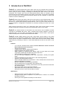
MFB-Doc-25
Sentinel Powerboard User Guide
Issue: A
Models: 93500-50, 93500-51, 93500-53, 93500-54
Firmware Version: 1.0
User Guide
MFB Products Pty Ltd
www.mfb.com.au
1 Disclaimer and Revisions
Operation of this equipment in a residential area may cause interference in which case the user,
at his or her own expense, will be required to take whatever measures may be required to
correct the interference.
Date
Issue
01 Feb 2012
MFB Products Pty Ltd
MFB-Doc-25. 30-Jan-2012
A
Comments
Initial Release
Issue: A
Sentinel Power Board User’s Guide
Page: 1 of 48
2 Warranty
MFB Products Pty Ltd warrants Sentinel
-
If used in accordance with all applicable instructions
-
To be free from defects in material and workmanship for a period of one year from the date of
initial purchase.
This warranty is voided if the customer uses the product in an unauthorized or improper way, or in an
environment for which it was not designed. Warranty does not apply to normal wear or to damage resulting
from accident, misuse, abuse or neglect.
MFB Products Pty Ltd
MFB-Doc-25. 30-Jan-2012
Issue: A
Sentinel Power Board User’s Guide
Page: 2 of 48
Table of Contents
1
DISCLAIMER AND REVISIONS..........................................................................................................................1
2
WARRANTY ........................................................................................................................................................2
3
INTRODUCTION TO SENTINEL .........................................................................................................................5
3.1
4
MODELS .................................................................................................................................. 6
QUICK INSTALL GUIDE .....................................................................................................................................7
4.1
MINIMUM REQUIREMENTS .......................................................................................................... 7
4.2
HARDWARE SETUP ................................................................................................................... 7
4.2.1
Ethernet Connections ................................................................................................... 7
4.2.2
Dual Digital Sensor Connection – Line 2...................................................................... 7
4.2.3
Serial Port Connection – Line 1.................................................................................... 7
5
ACCESSING SENTINEL VIA WEB INTERFACE ...............................................................................................8
6
INTRODUCTION TO USER GROUPS & SECURITY .........................................................................................9
6.1
ADMINISTRATOR GROUP............................................................................................................ 9
6.2
USER GROUP ......................................................................................................................... 10
6.3
SECURITY ON SENTINEL .......................................................................................................... 11
6.3.1
Browser Credentials ................................................................................................... 11
6.3.2
Forgotten Password ................................................................................................... 11
7
CONTROLLING & VIEWING STATUS OF SENSORS AND OUTLETS ..........................................................12
7.1
7.2
7.3
7.4
7.5
7.6
7.7
8
ALARMS ON SENTINEL...................................................................................................................................16
8.1
8.2
8.3
9
EMAIL MESSAGES ................................................................................................................... 17
LCD TEXT IN ALARM CONDITION .............................................................................................. 18
SNMP TRAP MESSAGE........................................................................................................... 18
CONFIGURING SENTINEL ...............................................................................................................................20
9.1
9.2
9.2.1
9.2.2
9.2.3
9.3
9.3.1
9.3.2
9.3.3
9.3.4
9.3.5
9.3.6
9.3.7
9.4
10
VIEW OUTLET STATUS, SENSOR STATUS & TOTAL CURRENT CONSUMPTION OF OUTLETS ............. 13
TURNING ON OUTLETS ............................................................................................................ 14
TURNING OFF OUTLETS .......................................................................................................... 14
REBOOTING OUTLETS ............................................................................................................. 14
GLOBAL ON ........................................................................................................................... 14
GLOBAL OFF .......................................................................................................................... 15
GLOBAL REBOOT .................................................................................................................... 15
OUTLET CONFIGURATION ........................................................................................................ 20
SENSOR CONFIGURATION ........................................................................................................ 21
Current Alarm Settings ............................................................................................... 21
Analogue Sensor Settings .......................................................................................... 22
Digital Sensor Settings ............................................................................................... 22
SENTINEL DEVICE CONFIGURATION .......................................................................................... 23
Device Identification Parameters................................................................................ 23
Network Interface Settings ......................................................................................... 23
SMTP Settings (Email Settings) ................................................................................. 24
SNMP Settings ........................................................................................................... 24
Serial Port Settings..................................................................................................... 24
Set Date & Time ......................................................................................................... 25
Loading Factory Defaults ........................................................................................... 25
MANAGE USERS ..................................................................................................................... 26
SERIAL PORT CONNECTION ON SENTINEL – LINE 1 .................................................................................27
10.1
SERIAL COMMAND TABLE ........................................................................................................ 28
11
DUAL DIGITAL SENSOR CONNECTION – LINE 2 .........................................................................................30
12
ALARM, CONFIGURATION AND EVENT LOGS ON SENTINEL....................................................................30
13
SNMP ON SENTINEL........................................................................................................................................32
13.1
INTRODUCTION TO SNMP FEATURES ON SENTINEL.................................................................... 32
13.2
SNMP IMPLEMENTATION ......................................................................................................... 32
13.3
SNMP TRAP IMPLEMENTATION .............................................................................................. 35
13.4
REQUIREMENTS ...................................................................................................................... 41
13.5
SETTING THE MIB FILE............................................................................................................ 41
13.6
INTERPRETING TRAPS ............................................................................................................. 41
13.6.1
Coldstart trap.............................................................................................................. 41
13.6.2
Temperature (Analogue) warning trap........................................................................ 42
13.6.3
Current Sensor Warning............................................................................................. 42
13.6.4
A digital sensor alarm trap.......................................................................................... 43
MFB Products Pty Ltd
MFB-Doc-25. 30-Jan-2012
Issue: A
Sentinel Power Board User’s Guide
Page: 3 of 48
13.6.5
Outlet State Change Trap Samples............................................................................ 43
13.6.6
A configuration update notification ............................................................................. 44
13.7
SNMP POLLING ..................................................................................................................... 45
14
HARDWARE SPECIFICATIONS.......................................................................................................................46
15
TROUBLESHOOTING.......................................................................................................................................47
15.1
TECHNICAL SUPPORT .............................................................................................................. 47
16
DECLARATION OF CONFORMITY ..................................................................................................................47
17
COPYRIGHT AND TRADEMARK .....................................................................................................................47
MFB Products Pty Ltd
MFB-Doc-25. 30-Jan-2012
Issue: A
Sentinel Power Board User’s Guide
Page: 4 of 48
3 Introduction to Sentinel
Sentinel
is a network based 240V power outlet control unit for computer server racks with
environmental monitoring features. It allows turning 240V powered devices on or off as well as
power cycling by just by visiting a webpage & controlling the power outlet of the device
connected. The ‘Current Load’ and the environmental sensor status on Sentinel can be
monitored via the web interface and the LCD screen on the device. In the case of exceeding
user set Current load or environmental thresholds Sentinel has the capability of notifying the
incident via email or SNMP traps.
Sentinel
allows viewing the status of the server rack power on each individual power outlet,
allows custom controlled timed reboots for each power outlet and adding delays on start-up in
the case of a power failure allowing selected devices to turn on prior to other devices in a
selected sequence. Configuration is performed by remotely accessing the device via a web
interface.
When network connectivity is down, as an alternative outlet control access method, Sentinel
provides a serial port connection to perform the fundamental control to your outlets.
Sentinel is a network element on the network, thus it will have its own IP address. Sentinel
comprises an embedded web server. With a standard web browser installed in almost all
computers today, you may easily view Sentinel web pages to monitor status, control power
outlets remotely and to view the Current load & sensor status.
Sentinel
includes SNMP features where each outlet status, sensor status or the current
consumption can be obtained via SNMP GET commands, thus allowing monitoring systems to
closely monitor the power of attached devices, sensor status and the current loading. SNMP
Traps notify any exceeding of sensor or current load thresholds as well as user action on the
outlets.
Features
o
o
o
o
o
o
o
o
o
o
o
o
o
o
o
o
10 or 20 web controlled power outlets (See Error! Reference source not found.
Error! Reference source not found.)
Current load monitoring
2 Digital sensor inputs to capture external alarms
Inbuilt temperature and humidity sensors.
SNMP enabled for obtaining device details, outlet & sensor status and current
consumption. SNMP traps for alarms and user outlet action.
SMTP enabled for notifying alarm conditions.
2 x row LCD panel displaying current load, temperature, humidity and system
status.
Powerful embedded microprocessor driven, with networking features.
Vertical or horizontal product versions.
LEDs to indicate outlets that are powered on. LED to indicate when Current load or
sensor thresholds are in jeopardy.
Remote configuration and monitoring capabilities.
Up to 30 entries each in configuration, event & alarm logs.
Two level protection in controlling. Administration user and up to three normal users
with restricted grants.
Each power outlet can be configured individually.
Clear status view of each power outlet on user interface.
Serial port access to control & view status of outlets
Applications
o
o
o
Allows total control on power outlets on server racks.
Configures device start up sequence in a power failure occasions for controlled
powering up devices.
Control your home appliances remotely from the Internet.
MFB Products Pty Ltd
MFB-Doc-25. 30-Jan-2012
Issue: A
Sentinel Power Board User’s Guide
Page: 5 of 48
3.1 Models
MFB Part No
93500-50
93500-51
Outlets
10
10
Description
Vertical Active Power Assembly, 10 x 10 amp Australian
outlets, with 10 amp double pole circuit breaker,
Temperature and Humidity sensor, dual digital inputs
Vertical Active Power Assembly, 10 x 10 amp IEC C13
outlets, with 10 amp double pole circuit breaker,
Temperature and Humidity sensor, dual digital inputs
93500-53
20
Vertical Active Power Assembly, 20 x 10 amp Australian
outlets, with 10 amp double pole circuit breaker,
Temperature and Humidity sensor, dual digital inputs
93500-54
20
Vertical Active Power Assembly, 20 x 10 amp IEC C13
outlets, with 10 amp double pole circuit breaker,
Temperature and Humidity sensor, dual digital inputs
MFB Products Pty Ltd
MFB-Doc-25. 30-Jan-2012
Issue: A
Sentinel Power Board User’s Guide
Page: 6 of 48
4 Quick Install Guide
This chapter will guide installing Sentinel on the network.
4.1 Minimum Requirements
The minimum requirements to install and access Sentinel are:
o
o
Access to the local network
A PC with a web browser (IE 6.0, Firefox 3.6 or higher recommended)
4.2 Hardware Setup
4.2.1
Ethernet Connections
Connect Ethernet cable to the Ethernet Socket. Supply power to server rack.
4.2.2
Dual Digital Sensor Connection – Line 2
There is a dual digital connection provided which is an RJ45 type connection.
Please refer to chapter XX for configuration details.
4.2.3
Serial Port Connection – Line 1
The Serial port connection is a RJ45 type connection.
Please see chapter 10 for configuration details.
MFB Products Pty Ltd
MFB-Doc-25. 30-Jan-2012
Issue: A
Sentinel Power Board User’s Guide
Page: 7 of 48
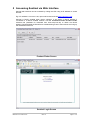
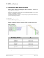
5 Accessing Sentinel via Web Interface
Sentinel web interface can be accessed by visiting the URL using its IP address on a web
browser.
Eg: if IP address is 192.168.1.105, open web browser and visit http://192.168.1.105/
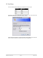
Sentinel is DHCP enabled when factory shipped. It will obtain a DHCP address if
connected to a DHCP enabled network. Use the Controlled Power Product Finder
software tool (available for download from www.csspl.com.au) to obtain the DHCP
address. Please disable the firewall as a troubleshooting event if this tool does not bring up
the IP address of the unit.
Product Finder Screen
Sentinel Login Screen
MFB Products Pty Ltd
MFB-Doc-25. 30-Jan-2012
Issue: A
Sentinel Power Board User’s Guide
Page: 8 of 48
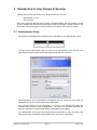
6 Introduction to User Groups & Security
Sentinel has two user groups that may operate the device. They are:
o
o
Administrator (1 user)
User (3 users)
Each user group has different level of grants. The Administrator user has grants to control
outlets, configure the device and sensor status as well as viewing the status of device. The
User group users have grants to view the status of the device and control the outlets.
6.1 Administrator Group
The product is released with the following user credentials for the ‘Administrator’ group.
Username
Password
admin
admin
To login as the administrator, click on ‘Login as an Administrator’ from the main web
page. Enter the administration username & password, and then click OK.
The administrator user is responsible for configuring the unit, its users & each outlet. An
administrator may also control each outlet & view status.
Note: Please configure the ‘secret question’ & ‘answer’ for the administrator within the
‘manage users’ section under ‘configuration’. - In case of a forgotten password the
answer is required to reset the administration password back to default.
The administrator should also set usernames and passwords for the user group. The
default User group credentials are described in the ‘user group’ subheading.
MFB Products Pty Ltd
MFB-Doc-25. 30-Jan-2012
Issue: A
Sentinel Power Board User’s Guide
Page: 9 of 48
6.2 User Group
The unit is released with the following user credentials for the ‘User’ group
Username
Password
user1
pwd1
user2
pwd2
user3
pwd3
To login as a user from the User group, click on ‘Login as a User’ from the main web
page, enter the username and password, and then click OK.
These users have permission to control each outlet & view the status of each outlet and
sensors. There are no grants to configure outlet or device configurations.
MFB Products Pty Ltd
MFB-Doc-25. 30-Jan-2012
Issue: A
Sentinel Power Board User’s Guide
Page: 10 of 48
6.3 Security on Sentinel
6.3.1
Browser Credentials
Authentication is required to view any of Sentinel web pages. Sentinel uses ‘basic
authentication’ via HTTP.
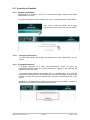
To logout from Sentinel, close the browser or click on the logout button on the interface.
Then, click on ‘close this window’ link to logout
from Sentinel. This will close the browser window.
6.3.1.1
6.3.2
Changing the Password
Only the administrator may change the passwords for both ‘administrator’ & ‘user’
groups.
Forgotten Password
A forgotten password for a user (non-administrative) cannot be reset. The
administrator should provide the correct password by logging in and retrieving the
password set for each user.
If the administrator password is forgotten, the only available option is to reset the
password by responding to the secret question set by the administrator. Answering this
question correctly will reset the administration username and password both to be
‘admin’.
PS: Note for the administrator: Please ensure that the secret question & answer is
updated when the device is configured for the first time.
MFB Products Pty Ltd
MFB-Doc-25. 30-Jan-2012
Issue: A
Sentinel Power Board User’s Guide
Page: 11 of 48
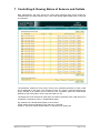
7 Controlling & Viewing Status of Sensors and Outlets
Both ‘Administrator’ and ‘User’ groups can control each individual power outlet. Outlets are
controlled from the ‘Outlet Control’ menu. This is the default page loaded when a user logs
in to Sentinel.
The parameter ‘Sequence Timer’ (Seq. Timer) is an important parameter for each outlet
and is displayed on this page. The ‘Sequence Timer’ is a value in seconds showing how
long it will take for an outlet to turn on when the rack is powered. (Note: the outlet startup
preference has to be setup in such a way that it will turn on)
The Sequence Timer will also be used when the outlet is rebooted. Each outlet will turn off
for duration of Sequence Timer + Global Reboot Delay.
Eg: Sentinel has a Global Reboot Delay of 30 seconds.
Power Outlet 10 has a Sequence Timer value of 14 seconds.
Outlet 10 ‘On Power Failure Outlet Startup’ is selected to be ‘Always On’
MFB Products Pty Ltd
MFB-Doc-25. 30-Jan-2012
Issue: A
Sentinel Power Board User’s Guide
Page: 12 of 48
When server rack is powered on: Outlet 10 will be powered on in 14 seconds
When outlet 10 is rebooted or global reboot is selected outlet 10 will be powered in 44
seconds.
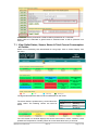
7.1 View Outlet Status, Sensor Status & Total Current Consumption
of Outlets
Status can be viewed by both administrator & user groups. Click on ‘Status Display’ from
the menu.
The legend describes the status of each outlet based on the colour.
The sensor status is updated every 15 seconds and is
colour coded. The following colours are used for
status
Display Colour
Green
Yellow
Red
Blue
Sensor Status
OK
Warning
Alarm
Shutdown
The LCD Screen on Sentinel displays the sensor status when in alarm condition. It also
updates the Temperature, Humidity sensor & Current load values every 3 seconds.
MFB Products Pty Ltd
MFB-Doc-25. 30-Jan-2012
Issue: A
Sentinel Power Board User’s Guide
Page: 13 of 48
7.2 Turning On Outlets
Select the outlet that you intend to turn on by clicking on the appropriate radio button. Eg:
if you wish to turn on ‘SafetyNet Series GSM’ outlet at outlet ID14, click on the ‘Turn ON’
radio button and then click the Apply’ button. Multiple outlets are also selectable.
Only an outlet than is in ‘Off’ position can be turned ‘On’. If the outlet is not in ‘Off’
position the command is ignored.
7.3 Turning Off Outlets
Select the outlet that you intend to turn off by clicking on the appropriate radio button.
Click the ‘Apply’ button. Multiple outlets are also selectable
Outlets will be turned off only if they were turned on or while rebooting. Turning off an
already off outlet will have not affect.
7.4 Rebooting Outlets
Select the ‘Reboot’ radio button of the outlet you intend to reboot and click the ‘Apply’
button. Multiple outlets are also selectable
Outlets will be rebooted only if they were turned on. Rebooting an already off outlet or a
rebooting outlet will have not affect.
Each outlet will reboot with a delay of ‘Sequence Timer’ + ‘On Power Failure Outlet
Startup’ seconds.
7.5 Global On
All outlets can be turned on by selecting this option. Select ‘Global ON’ radio button under
the Global Power Outlet Control heading and click apply.
PS: All outlets that are rebooting or turned off status will turn on.
MFB Products Pty Ltd
MFB-Doc-25. 30-Jan-2012
Issue: A
Sentinel Power Board User’s Guide
Page: 14 of 48
7.6 Global Off
All outlets can be turned off by selecting this option. Select ‘Global OFF’ radio button
under the Global Power Outlet Control heading and click apply
PS: All outlets that are rebooting or turned on status will turn off.
7.7 Global Reboot
All outlets can be rebooted by selecting this option. Select ‘Global Reboot’ radio button
under the Global Power Outlet Control heading and click apply
PS: All outlets that are turned on will reboot. Outlets that are turned off will remain as is.
Each outlet will reboot with a delay of ‘Sequence Timer’ + ‘On Power Failure Outlet
Startup’ seconds.
Sentinel Display Panel
MFB Products Pty Ltd
MFB-Doc-25. 30-Jan-2012
Issue: A
Sentinel Power Board User’s Guide
Page: 15 of 48
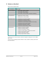
8 Alarms on Sentinel
Sentinel has the following alarms
Associated Sensor
Current Load Sensor
Alarm Type
Current load in warning condition
Current load in alarm condition
Current load in critical condition
Current load in normal condition ( clearance of an alarm)
Dual Digital Sensor
Digital sensor in alarm condition
Digital sensor in normal condition
Temperature Sensor
Temperature in low warning condition
Temperature in low alarm condition
Temperature in low shutdown condition
Temperature in normal condition ( clearance of an alarm)
Temperature in high warning condition
Temperature in high alarm condition
Temperature in high shutdown condition
Humidity Sensor
Humidity in low warning condition
Humidity in low alarm condition
Humidity in low shutdown condition
Humidity in normal condition ( clearance of an alarm)
Humidity in high warning condition
Humidity in high alarm condition
Humidity in high shutdown condition
In the event of any of these conditions, Sentinel is capable of notifying the user via SNMP
traps & email.
The front panel LCD display shall also indicate if in alarm condition. A blinking red LED will
also attract attention.
MFB Products Pty Ltd
MFB-Doc-25. 30-Jan-2012
Issue: A
Sentinel Power Board User’s Guide
Page: 16 of 48
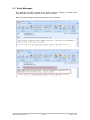
8.1 Email Messages
By configuring the SMTP settings & the relevant sensors, Sentinel can deliver email
notification when sensors get into and out of alarm conditions.
Below are some samples of emails that are sent out from Sentinel
MFB Products Pty Ltd
MFB-Doc-25. 30-Jan-2012
Issue: A
Sentinel Power Board User’s Guide
Page: 17 of 48
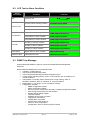
8.2 LCD Text in Alarm Condition
Sensor
Associated
N/A
Condition
LCD Text
X.XXXA
System is OK
X.X°C X.X%RH
All’s Well
Current Load in warning condition
!!Load warning X.XXXA
Current Load in alarm condition
!!Load alarm X.XXXA
Current Load in critical condition
!!Load critical X.XXXA
Temperature in warning condition
!!TMP [High|Low] warning
Temperature in alarm condition
!!TMP [High|Low] alarm
Temperature in critical condition
!!TMP [High|Low] shutdown
Humidity in warning condition
!!HMD [High|Low] warning
Humidity in alarm condition
!!HMD [High|Low] alarm
Humidity in critical condition
!!HMD [High|Low] shutdown
Dual Digital
Digital Senor in alarm condition
!!Digital Alarm [1|2]
Network Cable
Cable Disconnected
!!Network Disconnected
Current Load
Temperature
Humidity
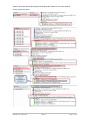
8.3 SNMP Trap Message
Sentinel delivered SNMP V1 traps up to three nominated Network Management
Elements.
Sentinel delivers SNMP traps in the following events:
Coldstart – indicate boot up
User turning on/off/rebooting outlet
User turning on/off/rebooting all outlets via global control
Current sensor reaching warning, alarm or critical levels; also on clearance, ie:
normal conditions
Temperature or Humidity sensor reaching low or high warning, alarm or
shutdown conditions. Also on clearance, ie: normal conditions
Digital sensor 1 or 2 going in or out of an alarm condition
Configuration updates:
o SNMP configuration update
o SMTP configuration update
o Sensor (Current, Temperature, Humidity or Digital) configuration update
o User forcing device reboot via web interface
o System default settings update
o Time/date update
o Updating device name or location
o Triggering of a test email
o Configuration of an outlet
o Configuration of the serial port
o Admin or users configuration
o Configuration, Alarm or Event log being cleared
MFB Products Pty Ltd
MFB-Doc-25. 30-Jan-2012
Issue: A
Sentinel Power Board User’s Guide
Page: 18 of 48
Sentinel Traps are defined and appropriate bindings are defined in CSS-TRAPS-MIB file.
Several sample traps below:
MFB Products Pty Ltd
MFB-Doc-25. 30-Jan-2012
Issue: A
Sentinel Power Board User’s Guide
Page: 19 of 48
9 Configuring Sentinel
Only the administration user can configure Sentinel.
The following can be configured:
o
o
o
o
o
o
Outlet configuration
Sensor configuration - Current Load, Temperature, Humidity and two digital
sensors
Sentinel device configuration, includes Network, SNMP, Serial Port, SMTP & Date
and Time
Loading factory defaults and rebooting via the interface
Manage users ( user names and passwords)
Clear alarm, configuration and event logs
Each of the above shall be described in the following sections.
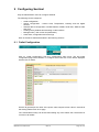
9.1 Outlet Configuration
Click on ‘Outlet Configuration’ from the ‘Configuration’ main menu: The first outlet
configuration page will be loaded. To configure each outlet click on the button displayed
with the ID’s of outlets.
Set the ID (optional) & the name of the power outlet, sequence timer value in seconds &
the startup preference & click ‘Apply’.
The ‘Global Reboot Delay’ can be set whilst setting any of the outlets. PS: note that this is
common to all outlets.
MFB Products Pty Ltd
MFB-Doc-25. 30-Jan-2012
Issue: A
Sentinel Power Board User’s Guide
Page: 20 of 48
9.2 Sensor Configuration
Navigate to ‘Sensor Configuration’ from the ‘Configuration’ main menu. The following
settings are configurable:
o
o
o
o
9.2.1
Set thresholds & preferences for the Current Load sensor
Set thresholds & preferences for the Temperature sensor
Set thresholds & preferences for the Humidity sensor
Set thresholds & preferences for the Dual Digital sensor
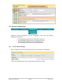
Current Alarm Settings
Allows configuring the Current Load Warning, Alarm & Critical levels in milliAmperes:
Tick the Send Email(s) check box for emails when thresholds are crossed.
MFB Products Pty Ltd
MFB-Doc-25. 30-Jan-2012
Issue: A
Sentinel Power Board User’s Guide
Page: 21 of 48
9.2.2
Analogue Sensor Settings
The analogue sensor (Temperature & Humidity) settings are configured as below:
Send Email(s): Tick to send an email(s) when temperature/humidity alarm moves from one
threshold limit to another
Sensor Name: A name given for sensor for identification purposes
Alarm Thresholds: Set the respective threshold values for warning, alarm & shutdown level
settings for low and high settings. These values are used to trigger analogue alarms.
Note: Shutdown alarms will not turn off outlets or shutdown the power board.
9.2.3
Digital Sensor Settings
Send Email(s): Tick to send an email(s) when digital alarm changes state
Sensor Name: A name given for sensor for identification purposes
Trigger delay: A delay value in seconds that is used to calculate the time to trigger the
digital sensor from change of state. If the sensor changes state for more than the Trigger
time limit the alarm shall be activated.
Contact Closure: ‘Normally Open’ setting is for open contact closure for non alarming state
and vice versa for ‘Normally Close’ state
MFB Products Pty Ltd
MFB-Doc-25. 30-Jan-2012
Issue: A
Sentinel Power Board User’s Guide
Page: 22 of 48
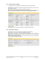
9.3 Sentinel Device Configuration
Navigate to ‘Device Settings’ from the ‘Configuration’ - > ‘Configure’ menu. The following
settings are configurable
o
o
o
o
o
o
o
Device identification parameters
Network interface settings
SMTP settings
SNMP community & Network Manager configuration
Serial port settings
Date & time of Sentinel
Loading factory defaults
There is also an option which allows rebooting Sentinel under this menu. Please note that
rebooting the device shall turn off all outlets and then each outlet will operate as per each
outlet’s start up preference as the device turns on.
9.3.1
Device Identification Parameters
Allows setting name & location details for Sentinel. Click ‘Apply’ to save settings.
Note: You must log out and log back in for these settings to take effect on the main page.
9.3.2
Network Interface Settings
Allows setting the network parameter & boot up preference. I.e.: DHCP or Static. If DHCP
is selected the network parameters entered will be ignored. Within 60 seconds (page
needs to be requested after 60 seconds) these fields shall be updated with the DHCP
obtained IP address. Click ‘Apply’ to save settings.
If a DHCP server is not detected, Sentinel sets in with a fall back IP address as described
below:
o
o
o
Fall back IP address: 192.168.1.100
Fall back subnet mask: 255.255.255.0
Fall back gateway: 0.0.0.0
MFB Products Pty Ltd
MFB-Doc-25. 30-Jan-2012
Issue: A
Sentinel Power Board User’s Guide
Page: 23 of 48
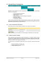
9.3.3
SMTP Settings (Email Settings)
Allows setting the SMTP mail server address, senders email address and the recipient
email addresses. Messages are sent to these recipients when in alarm condition for
sensors which are selected to send emails.
Ensure the SMTP Mail Server address is entered. If your mail server requires
authentication tick the Enable Authorisation check box & provide the username and
password for SMTP authentication.
You can test the email sending functionality by clicking the ‘Test Email’ button. Make sure
you have saved your settings before you click this button.
9.3.4
SNMP Settings
Allows setting read/write SNMP communities and Network managers for receiving trap
notifications.
9.3.5
Serial Port Settings
Allows configuring the serial port connection.
MFB Products Pty Ltd
MFB-Doc-25. 30-Jan-2012
Issue: A
Sentinel Power Board User’s Guide
Page: 24 of 48
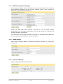
9.3.6
Set Date & Time
Use this section to update the device Date and Time
Ensure the date and time formats conform as displayed below:
Time - > HH:MM:SS – 24 hour format
Date - > DD/MM/YYYY
9.3.7
Loading Factory Defaults
The following action is performed:
o
o
o
o
o
o
User accounts, credentials, secret question & answer are set to defaults.
Device name & location shall be reset.
Each outlet name, ID, sequence timer, preference of startup & global reboot timer
values are reset.
SMTP, SNMP, Serial port settings are set to default
Alarm, configuration & event logs shall be cleared.
Digital and Analogue sensor thresholds and settings shall be set to default values
Network settings or present outlet status will not be affected. Though, when server rack is
powered on the next time, the default preference (ALWAYS ON) of outlets shall be used,
hence all outlets will be powered on.
MFB Products Pty Ltd
MFB-Doc-25. 30-Jan-2012
Issue: A
Sentinel Power Board User’s Guide
Page: 25 of 48
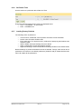
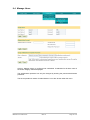
9.4 Manage Users
Click on ‘Manage Users’ to configure user credentials. Credentials for all three users of
the Users category shall be displayed.
The administrator password can only be changed by entering the present administrator
password.
The secret question & answer for administrator is can also be set under this menu.
MFB Products Pty Ltd
MFB-Doc-25. 30-Jan-2012
Issue: A
Sentinel Power Board User’s Guide
Page: 26 of 48
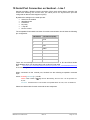
10 Serial Port Connection on Sentinel – Line 1
Sentinel provides a RS232 console connection (RJ45 type) which allows controlling the
outlets and obtaining the Current load. The serial port is an asynchronous port and
configured as data terminal equipment (DTE).
By default the settings on the serial port are:
Serial Port is enabled
9600 Baud rate
8 Data bits
No parity
1 stop bit
No flow control
The acceptable RJ45 based connection for serial communication should have the following
pin configuration:
PIN Number
Console Port (DTE)
1
RTS
2
-
3
TxD
4
GND
5
GND
6
RxD
7
-
8
CTS
There are commercially available RJ-45-to-DB-25 female DTE or RJ-45-to-DB-9 female
DTE adapters which can be used along with a rollover RJ45 cable.
http://www.cisco.com/en/US/products/hw/routers/ps214/products_tech_note09186a00801f5d85.shtml
See
as a reference guide.
When connected via the console port, Sentinel has the following acceptable command
input:
status <outlet# [command]> | <CUR>
outlet#: outlet number in two digit format. Alternatively, the word ‘ALL’ can be provided. 0120, ALL
command: intended action on the ‘outlet#’. Acceptable values are 'ON', 'OFF' or 'REBOOT'
Please see below table for total command set and responses.
MFB Products Pty Ltd
MFB-Doc-25. 30-Jan-2012
Issue: A
Sentinel Power Board User’s Guide
Page: 27 of 48
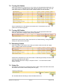
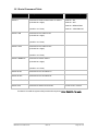
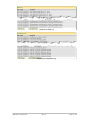
10.1 Serial Command Table
Command
Description
Possible Serial Response
status X
Command to retrieve outlet status of outlet X
Outlet X = ON
(X should be 2 digits)
Outlet X = OFF
Outlet X = REBOOTING
status X ON
(condition: 01<X<20)
Outlet X = STARTING UP
Command to turn outlet X ON
-
(X should be 2 digits)
(condition: 01<X<20)
status X OFF
Command to turn outlet X OFF
-
(X should be 2 digits)
(condition: 01<X<20)
status X REBOOT
Command to reboot outlet X
-
(X should be 2 digits)
(condition: 01<X<20)
status all ON
Command to turn all outlets on
-
status all OFF
Command to turn all outlets off
-
status all REBOOT
Command to reboot all outlets
-
status CUR
Command to obtain Current load
Current Load = 3.267A
If outlet ID is invalid the system shall provide with response: Error: Outlet>20. Try again
MFB Products Pty Ltd
MFB-Doc-25. 30-Jan-2012
Issue: A
Sentinel Power Board User’s Guide
Page: 28 of 48
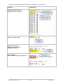
Below are extracted screenshots of requests and responses via the serial port
Activity
Screenshot
Request status of outlet 20
Request status of all outlets
Request ‘Current’ status
Request outlet 04 off
Request outlet 06 reboot
Request outlet 09 on
Error condition:
User requests outlet # not supported
MFB Products Pty Ltd
MFB-Doc-25. 30-Jan-2012
Issue: A
Sentinel Power Board User’s Guide
Page: 29 of 48
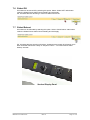
11 Dual Digital Sensor Connection – Line 2
Sentinel provides an RJ45 connection which allows input for two devices each having a
two point connection. A contact input adaptor is available which connects to the digital port
and allows for the connection of the two devices.
Contact Input Adaptor
12 Alarm, Configuration and Event Logs on Sentinel
Sentinel stores internal log entries for each alarm, event and configuration change that
takes place. These are three separate logs with up to 30 entries of each. When the log
reaches more than 30 entries, the oldest entry is removed and the latest entry is added.
Therefore, at any given time it is able to review the last 30 entries of alarms and events &
configuration changes. To keep a record of the alarms and events, it is recommended to
print of the table or copy and paste the table to a file (eg: to Notepad) frequently.
Each log entry consist a time stamp and a description of the alarm, event or the
configuration.
The configuration log can be viewed only by the administrator user group. The
administrator can also clear both types of logs by clicking the ‘Clear Log’ button.
A user from the ‘User group’ can access the event & alarm log. The configuration log will
not be accessible by this user.
Sample of the Event Log
MFB Products Pty Ltd
MFB-Doc-25. 30-Jan-2012
Issue: A
Sentinel Power Board User’s Guide
Page: 30 of 48
Sample of the Alarm Log
Sample of the Configuration Log
MFB Products Pty Ltd
MFB-Doc-25. 30-Jan-2012
Issue: A
Sentinel Power Board User’s Guide
Page: 31 of 48
13 SNMP on Sentinel
13.1 Introduction to SNMP Features on Sentinel
Sentinel supports SNMP (Simple Management Network Protocol) v1. Sentinel is an
SNMP agent where traps for alarming & events and GET/GETS commands are
supported for selected variables.
Sentinel has the capability to deliver traps up to three Network Manager Systems. Refer
to section 8.3 for SNMP configuration.
CSS-TRAPS-MIB.MIB file supplied by Computer Support Systems defines all the trap
types and the bindings for Sentinel.
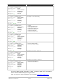
13.2 SNMP Implementation
Computer Support Systems enterprise ID is 14748.
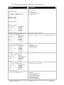
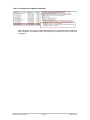
Sentinel supports the SNMP ‘System’ group in the MIB-II Objects:
SysDescr, sysObjectID, sysUpTime, sysContact, sysName, sysLocation & sysServices
Polling results below:
MIB-II System - OID Name
OID
sysDescr
1.3.6.1.2.1.1.1
sysObjectID
1.3.6.1.2.1.1.2
sysUpTime
1.3.6.1.2.1.1.3
sysContact
1.3.6.1.2.1.1.4
sysName
1.3.6.1.2.1.1.5
sysLocation
1.3.6.1.2.1.1.6
sysServices
1.3.6.1.2.1.1.7
Sentinel product OID is set as: 1.3.6.1.4.1.14748.2.7 also named as sentinel20Way in CSSTRAPS-MIB.MIB file.
MFB Products Pty Ltd
MFB-Doc-25. 30-Jan-2012
Issue: A
Sentinel Power Board User’s Guide
Page: 32 of 48
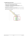
The following implementation is made for the sentinel20Way OID tree:
Object
Description
sentinel20_outlet1
to
sentinel20_outlet20
Provides the Outlet Status of outlet X where X is sentinel20_outletX
OID: 1.3.6.1.4.1.14748.1.7.1.1.1 to
1.3.6.1.4.1.14748.1.7.1.10.1
Eg:
sentinel20_outlet1
sentinel20_outlet2
…
…
sentinel20_outlet10
…
..
sentinel20_outlet20
Numerical syntax:
Integer (32 bit)
Base syntax:
INTEGER
Composed syntax:
INTEGER
Status:
mandatory
Max access:
read-only
Size list: 1: 0..3
sentinel20_currentConsumption_Reading
OID: 1.3.6.1.4.1.14748.2.7.2.1.1
Numerical syntax:
Integer (32 bit)
Base syntax:
INTEGER
Composed syntax:
INTEGER
Status:
mandatory
Max access:
read-only
Size list:
1: 0..40000
sentinel20_currentConsumption_Status
OID: 1.3.6.1.4.1.14748.2.7.2.1.2
Numerical syntax:
Integer (32 bit)
Base syntax:
INTEGER
Composed syntax:
INTEGER
Status:
mandatory
Max access:
read-only
Size list:
1: 0..4
sentinel20_temperature_Name
OID: 1.3.6.1.4.1.14748.2.7.2.2.1
Numerical syntax:
Octets
Base syntax:
OCTET STRING
Composed syntax:
DisplayString
Status:
mandatory
Max access:
read-only
Size list:
1: 0..42
sentinel20_temperature_Reading
OID: 1.3.6.1.4.1.14748.2.7.2.2.2
Numerical syntax:
Integer (32 bit)
Base syntax:
INTEGER
Composed syntax:
INTEGER
Status:
mandatory
Max access:
read-only
Size list: 1: -20..120
sentinel20_temperature_Status
OID: 1.3.6.1.4.1.14748.2.7.2.2.3
MFB Products Pty Ltd
MFB-Doc-25. 30-Jan-2012
00 = OUTLET OFF
01 = OUTLET ON
02 = OUTLET REBOOTING
03 = STARTING UP
Total current consumption - Sentinel 20
This value is in milli-amperes. To convert to Amperes, multiply by 1000
Alarm for Current Load Sensor
0 = level OK
1 = level at warning level
2 = level at alarm level
3 = level at critical level
Temperature Sensor Name - Sentinel 20
Temperature Sensor Reading - Sentinel 20
Use multiplier 0.1 for actual reading
Alarm for Temperature Sensor
0 = level OK
1 = level at high warning level
2 = level at high alarm level
3 = level at high shutdown level
4 = level at low warning level
5 = level at low alarm level
6 = level at low shutdown level
Issue: A
Sentinel Power Board User’s Guide
Page: 33 of 48
Object
Description
sentinel20_humidity_Name
OID: 1.3.6.1.4.1.14748.2.7.2.3.1
Numerical syntax:
Octets
Base syntax:
OCTET STRING
Composed syntax:
DisplayString
Status:
mandatory
Max access:
read-only
Size list: 1: 0..42
sentinel20_humidity_Reading
OID: 1.3.6.1.4.1.14748.2.7.2.3.2
Numerical syntax:
Integer (32 bit)
Base syntax:
INTEGER
Composed syntax:
INTEGER
Status:
mandatory
Max access:
read-only
Size list: 1: -20..120
sentinel20_humidity_Status
OID: 1.3.6.1.4.1.14748.2.7.2.3.3
Numerical syntax:
Integer (32 bit)
Base syntax:
INTEGER
Composed syntax:
INTEGER
Status:
mandatory
Max access:
read-only
Size list: 1: 0..6
sentinel20_digital_1_Name
OID: 1.3.6.1.4.1.14748.2.7.2.4.1
Numerical syntax:
Octets
Base syntax:
OCTET STRING
Composed syntax:
DisplayString
Status:
mandatory
Max access:
read-only
Size list: 1: 0..42
sentinel20_digital_1_Reading
OID: 1.3.6.1.4.1.14748.2.7.2.4.2
Numerical syntax:
Integer (32 bit)
Base syntax:
INTEGER
Composed syntax:
INTEGER
Status:
mandatory
Max access:
read-only
Size list: 1: 0..1
sentinel20_digital_2_Name
OID: 1.3.6.1.4.1.14748.2.7.2.5.1
Numerical syntax:
Octets
Base syntax:
OCTET STRING
Composed syntax:
DisplayString
Status:
mandatory
Max access:
read-only
Size list: 1: 0..42
sentinel20_digital_2_Reading
OID: 1.3.6.1.4.1.14748.2.7.2.5.2
Numerical syntax:
Integer (32 bit)
Base syntax:
INTEGER
Composed syntax:
INTEGER
Status:
mandatory
Max access:
read-only
Size list:
1: 0..1
Humidity Sensor Name - Sentinel 20
Humidity Sensor Reading - Sentinel 20
Use multiplier 0.1 for actual reading
Alarm for Humidity Sensor
0 = level OK
1 = level at high warning level
2 = level at high alarm level
3 = level at high shutdown level
4 = level at low warning level
5 = level at low alarm level
6 = level at low shutdown level
Digital Sensor One Name - Sentinel 20
Digital Sensor One Reading - Sentinel 20
1 = sensor in alarm condition
0 = sensor not in alarm condition
Digital Sensor Two Name - Sentinel 20
Digital Sensor Two Reading - Sentinel 20
1 = sensor in alarm condition
0 = sensor not in alarm condition
The above table provides information of OIDs to perform certain GET commands to
retrieve Sentinel related readings from a given NMS.
Note: The latest CSS-TRAPS-MIB.MIB is also available at http://www.csspl.com.au
MFB Products Pty Ltd
MFB-Doc-25. 30-Jan-2012
Issue: A
Sentinel Power Board User’s Guide
Page: 34 of 48
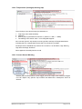
13.3 SNMP TRAP Implementation
CSS-TRAPS-MIB.MIB implements TRAP-TYPE objects defined by RFC-1215:
Trap types for Sentinel can be categorized in to four types:
1. Alarm type traps – for digital and analogue type sensors
2. Warning type traps – for analogue sensors ie: Temperature, Humidity & Current
3. Clear type traps – clearance of an alarm digital/analogue or other
4. Event type traps – Event Notifications.
The trap types can be recognized from the prefix of the trap type name. All trap types have
its Enterprise type set as ‘trapControl’ (1.3.6.1.4.1.14748.4)
The trapControl OID and the trap-type together has all information to capture and display
traps and its relevant bind information
MFB Products Pty Ltd
MFB-Doc-25. 30-Jan-2012
Issue: A
Sentinel Power Board User’s Guide
Page: 35 of 48
Name
OID
trapSource
OID:
Type:
trapDescr
OID:
1.3.6.1.4.1.14748.4.2
Numerical syntax:
Octets
Base syntax:
OCTET STRING
Composed syntax:
DisplayString
Status:
mandatory
Max access:
read-only
Size list: 1: 0..80
provides a textual description of the
particular trap
sensorID
OID:
1.3.6.1.4.1.14748.4.3
Numerical syntax:
Integer (32 bit)
Base syntax:
INTEGER
Composed syntax:
INTEGER
Status:
mandatory
Max access:
read-only
Size list: 1: 0..16
allows identifying the sensor number the
trap originates from
sensorValue
OID:
1.3.6.1.4.1.14748.4.4
Numerical syntax:
Integer (32 bit)
Base syntax:
INTEGER
Composed syntax:
INTEGER
Status:
mandatory
Max access:
read-only
Size list: 1: -200..200
provides the sensor value if originated
from an analogue type
(use multiplier 0.1 for actual reading)
currentConsumption
OID:
1.3.6.1.4.1.14748.4.5
Numerical syntax:
Integer (32 bit)
Base syntax:
INTEGER
Composed syntax:
INTEGER
Status:
mandatory
Max access:
read-only
Size list: 1: 0..40000
Current Consumption Sensor reading.
Value is in milli-Amperes. For value in
Amperes, multiply by 1000
outletID
OID:
1.3.6.1.4.1.14748.4.6
Numerical syntax:
Integer (32 bit)
Base syntax:
INTEGER
Composed syntax:
INTEGER
Status:
mandatory
Max access:
read-only
Size list: 1: 0..20
Provides an identification for outlet,
where an event occurred.
0 = first outlet
1 = second outlet
...
n = outlet n+1
outletName
OID:
1.3.6.1.4.1.14748.4.7
Numerical syntax:
Octets
Base syntax:
OCTET STRING
Composed syntax:
DisplayString
Status:
mandatory
Max access:
read-only
Size list: 1: 0..33
Outlet name where event occurred
MFB Products Pty Ltd
MFB-Doc-25. 30-Jan-2012
Description
1.3.6.1.4.1.14748.4.1
OBJECT-IDENTIFIER
Issue: A
points to the product the trap originates
from - i.e.: sentinel20Way
Sentinel Power Board User’s Guide
Page: 36 of 48
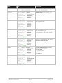
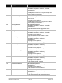
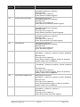
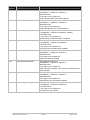
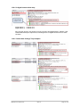
Trap-Type table is listed below. Based on the alarm/warning/clearance or event on Sentinel, the
below trap types are used.
Trap
Number
Trap-Type
Description
20
clearTemperatureSensor
ENTERPRISE trapControl
VARIABLES {trapSource, trapDescr, sensorID,
sensorValue}
DESCRIPTION
Trap origin is from trapSource.
Temperature sensor sensorID alarm is cleared.
Sensor reading is sensorValue
21
warningHighTemperatureSensor
ENTERPRISE trapControl
VARIABLES {trapSource, trapDescr, sensorID,
sensorValue}
DESCRIPTION
Trap origin is from trapSource.
Temperature sensor sensorID has triggered a high warning.
Sensor reading is sensorValue
22
warningLowTemperatureSensor
ENTERPRISE trapControl
VARIABLES {trapSource, trapDescr, sensorID,
sensorValue}
DESCRIPTION
Trap origin is from trapSource.
Temperature sensor sensorID has triggered a low warning.
Sensor reading is sensorValue
23
alarmHighTemperatureSensor
ENTERPRISE trapControl
VARIABLES {trapSource, trapDescr, sensorID,
sensorValue}
DESCRIPTION
Trap origin is from trapSource.
Temperature sensor sensorID has triggered a high alarm.
Sensor reading is sensorValue
24
alarmLowTemperatureSensor
ENTERPRISE trapControl
VARIABLES {trapSource, trapDescr, sensorID,
sensorValue}
DESCRIPTION
Trap origin is from trapSource.
Temperature sensor sensorID has triggered a low alarm.
Sensor reading is sensorValue"
25
clearHumiditySensor
ENTERPRISE trapControl
VARIABLES {trapSource, trapDescr, sensorID,
sensorValue}
DESCRIPTION
Trap origin is from trapSource.
Humidity sensor sensorID alarm is cleared.
Sensor reading is sensorValue.
26
warningHighHumiditySensor
ENTERPRISE trapControl
VARIABLES {trapSource, trapDescr, sensorID,
sensorValue}
DESCRIPTION
Trap origin is from trapSource.
Humidity sensor sensorID has triggered a high warning.
Sensor reading is sensorValue
27
warningLowHumiditySensor
ENTERPRISE trapControl
VARIABLES {trapSource, trapDescr, sensorID,
sensorValue}
DESCRIPTION
Trap origin is from trapSource.
Humidity sensor sensorID has triggered a low warning.
Sensor reading is sensorValue
MFB Products Pty Ltd
MFB-Doc-25. 30-Jan-2012
Issue: A
Sentinel Power Board User’s Guide
Page: 37 of 48
Trap
Number
Trap-Type
Description
28
alarmHighHumiditySensor
ENTERPRISE trapControl
VARIABLES {trapSource, trapDescr, sensorID,
sensorValue}
DESCRIPTION
Trap origin is from trapSource.
Humidity sensor sensorID has triggered a high alarm.
Sensor reading is sensorValue
29
alarmLowHumiditySensor
ENTERPRISE trapControl
VARIABLES {trapSource, trapDescr, sensorID,
sensorValue}
DESCRIPTION
Trap origin is from trapSource.
Humidity sensor sensorID has triggered a low alarm.
Sensor reading is sensorValue"
39
alarmDigitalSensor
ENTERPRISE trapControl
VARIABLES {trapSource, trapDescr, sensorID}
DESCRIPTION
Trap origin is from trapSource.
Digital sensor sensorID has triggered an alarm
40
clearDigitalSensor
ENTERPRISE trapControl
VARIABLES {trapSource, trapDescr, sensorID}
DESCRIPTION
Trap origin is from trapSource.
Digital sensor sensorID has cleared an alarm
101
eventSNMPUpdate
ENTERPRISE trapControl
VARIABLES {trapSource, trapDescr}
DESCRIPTION
Trap origin is from trapSource.
Event 'SNMP settings updated' triggered
102
eventEmailUpdate
ENTERPRISE trapControl
VARIABLES {trapSource, trapDescr}
DESCRIPTION
Trap origin is from trapSource.
Event 'Email settings updated' triggered
103
eventSensorSettingsUpdate
ENTERPRISE trapControl
VARIABLES {trapSource, trapDescr}
DESCRIPTION
Trap origin is from trapSource.
Event 'Sensor settings updated' triggered
105
eventDefaultsLoad
ENTERPRISE trapControl
VARIABLES {trapSource, trapDescr}
DESCRIPTION
Trap origin is from trapSource.
Event 'Defaults loaded' triggered
107
eventPasswordUpdate
ENTERPRISE trapControl
VARIABLES {trapSource, trapDescr}
DESCRIPTION
Trap origin is from trapSource.
Event 'Password changed' triggered
108
eventDeviceReset
ENTERPRISE trapControl
VARIABLES {trapSource, trapDescr}
DESCRIPTION
Trap origin is from trapSource.
Event 'Device reset via web interface' triggered
MFB Products Pty Ltd
MFB-Doc-25. 30-Jan-2012
Issue: A
Sentinel Power Board User’s Guide
Page: 38 of 48
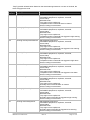
Trap
Number
Trap-Type
Description
109
eventTimeDateUpdate
ENTERPRISE trapControl
VARIABLES {trapSource, trapDescr}
DESCRIPTION
Trap origin is from trapSource.
Event 'Date/Time updated' triggered
110
eventDeviceParamsUpdate
ENTERPRISE trapControl
VARIABLES {trapSource, trapDescr}
DESCRIPTION
Trap origin is from trapSource.
Event 'Device name/location updated' triggered
111
eventNetworkParamsUpdate
ENTERPRISE trapControl
VARIABLES {trapSource, trapDescr}
DESCRIPTION
Trap origin is from trapSource.
Event 'Network parameters changed' triggered
116
eventLogCleared
ENTERPRISE trapControl
VARIABLES {trapSource, trapDescr}
DESCRIPTION
Trap origin is from trapSource.
Event 'Alarm and Event log cleared' triggered
125
eventTestEmail
ENTERPRISE trapControl
VARIABLES {trapSource, trapDescr}
DESCRIPTION
Trap origin is from trapSource.
Event 'Test Email' triggered
126
eventOutletTurnedOn
ENTERPRISE trapControl
VARIABLES { trapSource, trapDescr, outletID, outletName
}
DESCRIPTION
Trap origin is from trapSource.
Event 'Outlet Turned On' triggered. Outlet id is denoted by
outletID. Outlet name is outletName"
127
eventOutletTurnedOff
ENTERPRISE trapControl
VARIABLES { trapSource, trapDescr, outletID, outletName
}
DESCRIPTION
Trap origin is from trapSource.
Event 'Outlet Turned Off' triggered. Outlet id is denoted by
outletID. Outlet name is outletName"
128
eventOutletTurnedRebooted
ENTERPRISE trapControl
VARIABLES { trapSource, trapDescr, outletID, outletName
}
DESCRIPTION
Trap origin is from trapSource.
Event 'Outlet Rebooted' triggered. Outlet id is denoted by
outletID. Outlet name is outletName
129
eventGlobalOutletOn
ENTERPRISE trapControl
VARIABLES { trapSource, trapDescr }
DESCRIPTION
Trap origin is from trapSource.
Event 'Global Outlets Turned On' triggered
MFB Products Pty Ltd
MFB-Doc-25. 30-Jan-2012
Issue: A
Sentinel Power Board User’s Guide
Page: 39 of 48
Trap
Number
Trap-Type
Description
130
eventGlobalOutletOff
ENTERPRISE trapControl
VARIABLES { trapSource, trapDescr }
DESCRIPTION
Trap origin is from trapSource.
Event 'Global Outlets Turned Off' triggered
131
eventGlobalOutletReboot
ENTERPRISE trapControl
VARIABLES { trapSource, trapDescr }
DESCRIPTION
Trap origin is from trapSource.
Event 'Global Reboot on Outlets' triggered
132
eventOutletConfigured
ENTERPRISE trapControl
VARIABLES { trapSource, trapDescr, outletID }
DESCRIPTION
Trap origin is from trapSource.
Outlet bearing 'outletID' has been configured
133
eventCurrentThresholdUpdate
ENTERPRISE trapControl
VARIABLES { trapSource, trapDescr }
DESCRIPTION
Trap origin is from trapSource.
Current Sensor threshold values updated
134
eventSerialPortParamsUpdate
ENTERPRISE trapControl
VARIABLES { trapSource, trapDescr }
DESCRIPTION
Trap origin is from trapSource.
Serial Port Settings Updated
135
eventUserParamsUpdate
ENTERPRISE trapControl
VARIABLES { trapSource, trapDescr }
DESCRIPTION
Trap origin is from trapSource.
User Parameters updated. User names or passwords have
been updated
136
eventAdminUserParamsUpdate
ENTERPRISE trapControl
VARIABLES { trapSource, trapDescr }
DESCRIPTION
Trap origin is from trapSource.
Administrator User Parameters updated
137
eventConfigurationLogCleared
ENTERPRISE trapControl
VARIABLES { trapSource, trapDescr }
DESCRIPTION
Trap origin is from trapSource.
Configuration Log Cleared
MFB Products Pty Ltd
MFB-Doc-25. 30-Jan-2012
Issue: A
Sentinel Power Board User’s Guide
Page: 40 of 48
13.4 Requirements
o
o
A Network Manger System installed on your network or a SNMP sniffer program
installed on your PC to detect SNMP traps.
Correct SNMP configuration panel settings.
13.5 Setting the MIB File
Use the CSS-TRAPS-MIB.MIB file and make it available for the Network Manager
Software. The latest MIB file is located at http://www.csspl.com.au. The SNMP software
will allow configure/add paths to where the MIB file is. Read the SNMP software help files
to find out how to apply MIB paths on your NMS
Once the MIB path is effectively applied the trap bindings will indicate the details of the
trap message.
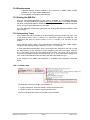
13.6 Interpreting Traps
Every SNMP trap is accompanied by an OID indicating the device of the trap origin. This
is provided by OID 1.3.6.1.4.1.14748.4.1 or ‘trapSource’ object in the MIB File. The
‘trapSource’ will point at ‘Sentinel 20Way’ (1.3.6.1.4.1.14748.2.7) at all times for this
product.
Every trap also binds a string, which describes the notification in plain simple English.
The OID of the message string is ‘trapDescr’ (1.3.6.1.4.1.14748.4.2).
In most alarm/warning/notification cases, more binding are attached to the trap, so that
the alarm/warning or the notification can be handled by the network manager software.
E.g. 1: the sensor value is sent for analogue type sensors. This value can be set to be
checked by the NMS to perform third party action. E.g. 2: If an outlet state is change by a
user, outlet ID & outlet Name are sent along with the appropriate trap type.
A few samples of the SNMP traps detected on a SNMP sniffer programs is depicted
below.
13.6.1 Coldstart trap
The bindings in the above image give indication of:
1. System description: Gives the software version and model name.
2. System up time: How long the device has been up for.
The above bindings are objects on the MIB-II implementation.
MFB Products Pty Ltd
MFB-Doc-25. 30-Jan-2012
Issue: A
Sentinel Power Board User’s Guide
Page: 41 of 48
13.6.2 Temperature (Analogue) warning trap
The 4 bindings in the above image give indication of:
1.
2.
3.
4.
Trap Origin from Sentinel 20Way
trapDescr
Warning trap is generated from Sensor 0 ( Sensor 0 = TMP, 1 = HMD)
The reading of the sensor value = 18.3 centigrade degrees
Also note the ‘Specific’ trap lookup is set as type #22, warningLowTemperatureSensor
indicating that it is a temperature sensor that is in low warning condition.
Similarly there are individual trap numbers of Low Alarm, Low Shutdown, High Warning,
High Alarm and High Shutdown.
Same applies for Humidity Sensor as well.
13.6.3 Current Sensor Warning
Similarly Alarm and Shutdown Current trigger points send traps, thus network managers
now can capture very specific Trap numbers and determine a subsequent action as
desired.
MFB Products Pty Ltd
MFB-Doc-25. 30-Jan-2012
Issue: A
Sentinel Power Board User’s Guide
Page: 42 of 48
13.6.4 A digital sensor alarm trap
Digital Sensor 1 = Sensor ID 0
Digital Sensor 2 = Sensor ID 2
Also note the ‘Specific’ trap lookup is set as type #39, alarmDigitalSensor, Module: CSSTRAPS-MIB, Enterprise: trapControl, indicating that it is a digital sensor that is in alarm
condition.
13.6.5 Outlet State Change Trap Samples
MFB Products Pty Ltd
MFB-Doc-25. 30-Jan-2012
Issue: A
Sentinel Power Board User’s Guide
Page: 43 of 48
13.6.6 A configuration update notification
Note the specific trap type is eventOutletConfigured, #132 indicating that the Outlet has
been configured. The OutletID within the bindings (#3) reveals as to which outlet was
configured.
MFB Products Pty Ltd
MFB-Doc-25. 30-Jan-2012
Issue: A
Sentinel Power Board User’s Guide
Page: 44 of 48
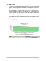
13.7 SNMP Polling
It is possible for the Network Manager Software (NMS) to poll the current sensor/outlet
status and values of analogue sensors periodically and store for graphing purposes. For
digital alarms the poll reply will indicate 1 or 0, where 1 is interpreted as an active alarm
and 0 as an inactive alarm. If sensors are disabled, polled reply will indicate a zero value.
The values retrieved for analogue sensors (including Current) are integers hence a
temperature, humidity value is shown as a multiplication of 10. The Current sensor value
is shown in milli-amps. Most SNMP graphing tools provide a method to view the graph by
using a customised multiplier. In this case, use the multiplier 0.1 to retrieve the exact
value for temperature or humidity type sensor. For example, temperature value 25.6°C is
retrieved as 256 & humidity value 60.4% is retrieved as 604.
Below is sample screen shot of a temperature sensor graph polled via SNMP using a tool
named as Paessler Router Traffic Grapher. (http://www.paessler.com)
MFB Products Pty Ltd
MFB-Doc-25. 30-Jan-2012
Issue: A
Sentinel Power Board User’s Guide
Page: 45 of 48
14 Hardware Specifications
Network Interface
o
o
o
RJ45 Ethernet 10Base-T, Realtek Semiconductors
LED indication: 10Base-T TX Activity, Full/half duplex.
Network Compatibility: Ethernet: Version 2.0/IEEE 802.3
Sentinel MCU Operating Conditions
o
o
Temperature range: -20°C to +70°C
Humidity range: 5 - 95%, non condensing
Power Requirements & Specifications
o
o
o
Input power: 240V A/C 50-60Hz
Current usage: 380 mA for MCU
Total outlet supply: 16A rated. (TBD)
Inbuilt Temperature and Humidity Sensor Specifications
o
o
o
o
Humidity Accuracy ±3.5 % RH,
Temperature Accuracy ±0.5 @ 25°C
Range –20°C to 100°C and 0 to 100%
Power consumption 28µA
LCD Panel Specifications
o
2 x 8 char LCD
MFB Products Pty Ltd
MFB-Doc-25. 30-Jan-2012
Issue: A
Sentinel Power Board User’s Guide
Page: 46 of 48
15 Troubleshooting
15.1 Technical Support
For any technical difficulties contact CSS technical support at:
Email: [email protected]
Telephone:
Fax:
+613-9419 3955
+613-9419 3509
Please have the following details when you contact CSS technical staff:
o
o
o
o
o
Model of product with software version.
Serial number (Label on back panel or from the main menu display)
Date of purchase
Clear definition of problem
Steps taken so far to fix problem
16 Declaration of Conformity
Manufacturer’s Name & Address:
Computer Support Systems Pty Ltd,
373 Johnston Street, Abbotsford, Victoria 3067, Australia.
Product Name & Manufacturers Model Numbers:
Sentinel 20 Way (ZVA1120, ZVA1320, ZVA2420)
Sentinel 10 Way (ZHA1110, ZHA1310, ZHA2410, ZVA1110, ZVA1310, ZVA2410)
17 Copyright and Trademark
© 2010, Computer Support Systems
All rights reserved. No part of the contents of this manual may be transmitted or reproduced in any form or by any
means without the written permission of Computer Support Systems. Computer Support Systems reserves the right to
make changes and improvements to its products without providing notice.
Ethernet is a trademark of XEROX Corporation.
Computer Support Systems Pty Ltd.
Head Office:
373 Johnston Street
Abbotsford
VICTORIA 3067
Australia
Telephone: - 61 3 9419 3955
Facsimile: - 61 3 9419 3509
Web Address: www.csspl.com.au
[email protected]
[email protected]
MFB Products Pty Ltd
MFB-Doc-25. 30-Jan-2012
Issue: A
Sentinel Power Board User’s Guide
Page: 47 of 48