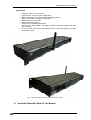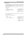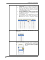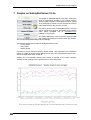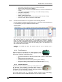
1
SafetyNet Series 5 Lite User Manual Document Revision CSSS5L 12/09 SafetyNet Series 5 Lite Version 1.01 SafetyNet Series Lite 5 User Manual Copyright and Trademark © 2008, Computer Support Systems All rights reserved. No part of the contents of this manual may be transmitted or reproduced in any form or by any means without the written permission of Computer Support Systems. Computer Support Systems reserves the right to make changes and improvements to its products without providing notice. Ethernet is a trademark of XEROX Corporation. Java™ is a trademark or a registered trademark of Sun Microsystems, Inc. in the United States and other countries. Computer Support Systems Pty Ltd. Head Office: 373 Johnston Street Abbotsford VICTORIA 3067 Australia Telephone: Facsimile: Web Address: - 61 3 9419 3955 61 3 9419 3509 www.csspl.com.au [email protected] [email protected] SafetyNet Series 5 Lite by Computer Support Systems -i- CSSS5L 12/09 SafetyNet Series Lite 5 User Manual Disclaimer and Revisions Operation of this equipment in a residential area may cause interference in which case the user, at his or her own expense, will be required to take whatever measures may be required to correct the interference. Date 11/11/2009 17/12/2009 Revision CSSS5L 11/09 CSSS5L 12/09 Comments NK Initial Release Updated Camera View Support SafetyNet Series 5 Lite by Computer Support Systems - ii - CSSS5L 12/09 SafetyNet Series Lite 5 User Manual Declaration of Conformity Manufacturer’s Name & Address: Computer Support Systems Pty Ltd, 373 Johnston Street, Abbotsford, Victoria 3067, Australia. Product Name Model: SafetyNet Series 5 Lite Environmental Monitoring System. Models include ZSN5002P & ZSN5002G SafetyNet Series 5 Lite by Computer Support Systems - iii - CSSS5L 12/09 SafetyNet Series Lite 5 User Manual Warranty Computer Support Systems warrants SafetyNet Series 5 Lite - If used in accordance with all applicable instructions - To be free from defects in material and workmanship for a period of one year from the date of initial purchase. This warranty is voided if the customer uses SafetyNet Series 5 Lite in an unauthorized or improper way, or in an environment for which it was not designed. Warranty does not apply to normal wear or to damage resulting from accident, misuse, abuse or neglect. SafetyNet Series 5 Lite by Computer Support Systems - iv - CSSS5L 12/09 SafetyNet Series Lite 5 User Manual SafetyNet Series 5 Lite Instructions When using this product, basic safety precautions should always be followed to reduce the risk of fire, electric shock, and injury to persons, including the following: 1. 2. Read and understand all instructions. Unplug this product from the wall outlet before cleaning. Do not use liquid cleaners or aerosol cleaners. Use a damp cloth for cleaning. 3. Do not use this product in an outdoor environment or near water, for example, near a bathtub, washbowl, kitchen sink or laundry tub, in a wet basement, or near a swimming pool. 4. Do not place this product on an unstable surface. The product may fall, causing serious damage to the product. 5. This product should never be placed near or over a radiator or heat register. This product should not be placed in a built-in installation unless proper ventilation is provided. 6. Do not allow anything to rest on the power cord. Do not locate this product where the cord will be abused by walking on or over it. 7. Do not overload wall outlets and extension cords as this can result in the risk of fire or electric shock. 8. Never push objects of any kind into this product through the slots as they may touch dangerous voltage points or short out parts that could result in a risk of fire or electrical shock. Never spill liquid of any kind on the product. 9. To reduce the risk of electrical shock, do not disassemble this product. Opening or removing covers will expose you to dangerous voltages or other risks. Incorrect re-assembly can cause electric shock when the appliance is subsequently used. 10. Unplug this product from the wall outlet and return to Computer Support Systems for repairs under the following conditions: a) When the power supply cord or plug is damaged. b) If liquid has been spilled into the product. c) If the product has been exposed to rain or water. d) If the product does not operate normally by following the operating instructions. Adjust only those controls that are covered by the operating instructions because improper adjustment of other controls may result in damage and will often require extensive work by a qualified technician to restore the product to normal operation. e) If the product has been dropped or has been damaged. f) If the product exhibits a distinct change in performance. 11. Do not use sensors that are not supplied by Computer Support Systems SafetyNet Series 5 Lite by Computer Support Systems -v- CSSS5L 12/09 SafetyNet Series Lite 5 User Manual Table of Contents COPYRIGHT AND TRADEMARK................................................................................................................................... I DISCLAIMER AND REVISIONS .................................................................................................................................... II DECLARATION OF CONFORMITY.............................................................................................................................. III WARRANTY ..................................................................................................................................................................IV 1 INTRODUCTION TO SAFETYNET SERIES 5 LITE ........................................................................................... 1 1.1 1.2 2 AVAILABLE SAFETYNET SERIES 5 LITE MODELS........................................................................... 2 SAFETYNET SERIES 5 LITE CONCEPT DIAGRAM ........................................................................... 3 QUICK INSTALL GUIDE ..................................................................................................................................... 4 2.1 2.2 2.3 REQUIREMENTS FOR A SUCCESSFUL INSTALLATION ...................................................................... 4 HARDWARE INSTALLATION ......................................................................................................... 4 ASSIGNING AN IP ADDRESS ........................................................................................................ 4 3 ASSUMPTIONS ................................................................................................................................................... 6 4 INTRODUCTION TO SAFETYNET SERIES 5 LITE WEB INTERFACE ............................................................ 7 4.1 SAFETYNET SERIES 5 LITE WEB INTERFACE – MAIN PAGE/VIEWER ............................................... 7 4.1.1 Menu Item – Viewer ..................................................................................................... 8 4.1.2 Menu Item – View Camera ........................................................................................... 8 4.1.3 Menu Item – View Graphs ............................................................................................ 8 4.1.4 Menu Item – View Logs ................................................................................................ 8 4.1.5 Menu Item – Sensors & Relays .................................................................................... 8 4.1.6 Menu Item – Settings ................................................................................................... 8 4.1.7 Menu Item – Logout ..................................................................................................... 8 4.2 SECURITY ON SAFETYNET SERIES 5 LITE .................................................................................... 8 4.2.1 Password Authentication .............................................................................................. 8 4.2.2 Forgotten Password ..................................................................................................... 9 4.2.3 Timed Redirection based on Inactivity .......................................................................... 9 5 SAFETYNET SERIES 5 LITE VIEWER ............................................................................................................ 10 5.1 6 RELAY STATUS ....................................................................................................................... 13 CONFIGURING SAFETYNET SERIES 5 LITE ................................................................................................. 14 6.1 SETTINGS MENU ITEM ............................................................................................................. 14 6.1.1 Device Settings .......................................................................................................... 14 6.1.2 Network Interface ....................................................................................................... 15 6.1.3 SMTP Configuration ................................................................................................... 15 6.1.4 SNMP Configuration ................................................................................................... 16 6.1.5 Modem/SMS Configuration - PSTN Modem based units ........................................... 16 6.1.6 GSM Modem/SMS Configuration – GSM Modem based units ................................... 17 6.1.7 System Clock Settings................................................................................................ 17 6.1.8 Camera Settings ......................................................................................................... 18 6.1.9 System Maintenance .................................................................................................. 18 6.2 SENSOR & RELAY MENU ITEM .................................................................................................. 19 6.2.1 Sensor Configuration .................................................................................................. 19 6.2.2 Relay Configuration .................................................................................................... 23 6.2.3 IP Address Monitoring ................................................................................................ 24 6.2.4 Sensor Trigger Action ................................................................................................. 24 7 GRAPHS ON SAFETYNET SERIES 5 LITE ..................................................................................................... 27 8 ALARM AND EVENT LOGS ON SAFETYNET SERIES 5 LITE ...................................................................... 29 8.1 ALARM LOG............................................................................................................................ 29 8.2 EVENT LOG ............................................................................................................................ 31 8.2.1 Clearing of Alarm and Event Logs .............................................................................. 31 9 OPERATION OF SAFETYNET SERIES 5 LITE ............................................................................................... 32 9.1 BASIC OPERATION .................................................................................................................. 32 9.2 EXTERNAL SENSORS ............................................................................................................... 32 9.2.1 Temperature and Humidity Sensors ........................................................................... 32 9.2.2 Fluid Detectors ........................................................................................................... 33 9.2.3 Smoke Detectors ........................................................................................................ 33 9.2.4 Digital Sensors ........................................................................................................... 34 SafetyNet Series 5 Lite by Computer Support Systems - vi - CSSS5L 12/09 SafetyNet Series Lite 5 User Manual 9.2.5 DC Voltage Detectors ................................................................................................. 34 9.2.6 AC Voltage Detector ................................................................................................... 34 9.2.7 PIR Motion Detector ................................................................................................... 34 9.3 INBUILT PSTN MODEM............................................................................................................ 34 9.3.1 Modem Initialisation Strings........................................................................................ 35 9.4 INBUILT GSM MODEM ............................................................................................................. 38 9.5 EMAIL MESSAGING FROM SAFETYNET SERIES 5 LITE ................................................................. 38 9.6 NETWORK INTERFACE AND TRAFFIC FROM SAFETYNET SERIES 5 LITE ......................................... 38 10 SMS/PAGER MESSAGES FROM SAFETYNET SERIES 5 LITE .................................................................... 40 10.1 INTRODUCTION TO SMS/PAGER MESSAGES FROM SAFETYNET SERIES 5 LITE ............................. 40 10.2 SMS MESSAGES USING THE GSM MODEM ............................................................................... 40 10.2.1 Requirements for SMS Messages via the GSM Modem ............................................ 40 10.2.2 Limitations .................................................................................................................. 40 10.3 SMS/PAGER MESSAGES USING THE INTERNAL PSTN MODEM .................................................... 40 10.3.1 Requirements for SMS Messages using the Modem ................................................. 41 10.3.2 Subscribing to a Paging Service to Receive SMS Messages ..................................... 41 10.3.3 Limitations .................................................................................................................. 41 10.4 SAMPLE MESSAGES ................................................................................................................ 41 11 SNMP ON SAFETYNET SERIES 5 LITE .......................................................................................................... 43 11.1 11.2 11.3 11.4 11.5 11.6 11.7 11.8 INTRODUCTION TO SNMP FEATURES ON SAFETYNET SERIES 5 LITE ........................................... 43 SNMP IMPLEMENTATION ......................................................................................................... 43 SNMP TRAP IMPLEMENTATION .............................................................................................. 45 REQUIREMENTS ...................................................................................................................... 53 HOW TO RECEIVE TRAPS ......................................................................................................... 53 SETTING THE MIB FILE............................................................................................................ 54 INTERPRETING SAFETYNET SERIES 5 LITE TRAPS ...................................................................... 54 SNMP POLLING ..................................................................................................................... 56 12 HARDWARE SPECIFICATIONS....................................................................................................................... 58 13 TROUBLESHOOTING....................................................................................................................................... 60 13.1 TECHNICAL SUPPORT .............................................................................................................. 61 14 GLOSSARY ....................................................................................................................................................... 62 15 FREQUENTLY ASKED QUESTIONS (FAQ’S) ................................................................................................ 63 SafetyNet Series 5 Lite by Computer Support Systems - vii - CSSS5L 12/09 SafetyNet Series Lite 5 User Manual 1 Introduction to SafetyNet Series 5 Lite SafetyNet Series 5 Lite is modern network based Environmental Monitoring System (EMS). It is capable of monitoring surrounding environment conditions using connected sensors. In alarm conditions, SafetyNet Series 5 Lite alerts notification via SNMP (Simple Network Management Protocol), email messaging (SMTP Protocol), via SMS messaging, Pager notification and by its web interface. Blinking LED’s, a buzzer and a strobe is also activated on alarm and will attract attention on error conditions. The device is capable of activating a relay on alarm activation to activate desired external peripheral. This product is ideal to monitor facility services and notify of potential environmental problems, which may impact on network operations. Additionally, the unit can monitor an IP address and enter into an alarm condition when the IP address does not respond to a ping command. SafetyNet Series 5 Lite comprises an embedded web server and a powerful processor. An attractive, user friendly interface is used for viewing or configuring the device. This interface is accessible via a standard Java enabled web browser installed in almost all computers today. Features o o o o o o o o o o o o o o o o Powerful embedded microprocessor driven, with networking feature o TCP/IP, UDP, DHCP, HTTP, SNMP, SMTP, ICMP, NTP protocols are supported Up to 2 hours of internal battery backed operation in power failures 19” inch rack mountable, compact size, light weight and sleek design SNMP (V1) features to notify error conditions via traps and allows polling data of sensors/relay Email messages up to three given email addresses notifying alarm conditions. SMS messaging or pager messaging via a network interface independent internal PSTN or GSM modem.* Remote configuration and monitoring capabilities via a web interface. User friendly and attractive user interface Six user-configurable contact sensor inputs o Temperature, Humidity, DC Voltage, Digital, Smoke, Fluid, Security etc o Use of dual temperature & humidity sensors** One relay - capable of being controlled manually via a web interface or by sensors upon alarms IP monitoring Optional strobe and a buzzer to indicate error conditions. Blinking LED on unit indicates alarm conditions Inbuilt plotting of graphs for up to four analogue sensors with weekly, daily and 2 hour history Up to 40 entries on alarm and event logs Integrating Camera view on device with compatible IP cameras. Firmware upgrades over the network * Only one type of modem can be ordered on one unit * Utilises two of available sensor input ports. One dual physical sensor is used. SafetyNet Series 5 Lite by Computer Support Systems -1- CSSS5L 12/09 SafetyNet Series Lite 5 User Manual Applications o o o o o o o o o Computer server room monitoring Computer rack monitoring and management Alarm consolidation from other network disabled systems Monitoring of other controlled environments Monitoring of servers or PCs Water monitoring systems Remote door controlling applications Remote PoP, data centers, co-locations, telecom switching facilities and utility site monitoring IP camera view via a single web interface on the monitoring system by using a compatible camera Figure 1: SafetyNet Series 5 Lite Environmental Monitoring System 1.1 Available SafetyNet Series 5 Lite Models SafetyNet Series 5 Lite by Computer Support Systems -2- CSSS5L 12/09 SafetyNet Series Lite 5 User Manual Model Number ZSN5002P ZSN5002G Description Powered by 240 Volt A/C input, includes a PSTN modem & battery backup Powered by 240 Volt A/C input, includes a GSM modem & battery backup 1.2 SafetyNet Series 5 Lite Concept Diagram Network Operations Center Remote Environment SMS Messages via the GSM Network Network Management Software SafetyNet Series 5 – GSM Modem Internet/LAN SafetyNet Series 5 – PSTN Modem Emails/SNMP/Web Browser Connection to the PSTN Network Figure 2: Network Concept SafetyNet Series 5 Lite by Computer Support Systems -3- CSSS5L 12/09 SafetyNet Series Lite 5 User Manual 2 Quick Install Guide 2.1 Requirements for a successful Installation o o Access to the local area network & UDP port 30705 available for communication. Java enabled web browser. (Java™ 2 Runtime Environment, Standard Edition, Version 1.6.0. or higher) 2.2 Hardware Installation 1. SafetyNet Series 5 Lite should be turned off. 2. Connect the Ethernet cable to the interface located on the front panel. 3. Connect necessary inputs on to the back of SafetyNet device. 4. Connect power cable and turn unit on. 2.3 Assigning an IP address DHCP on the network interface is enabled by factory default. Upon non-detection of a DHCP server on the network the unit falls back to IP address 192.168.1.100 with a gateway of 255.255.255.0. An IP address can be applied to the unit by: 1. DHCP server automatic IP allocation. ( factory default) 2. Web browser via the ‘Settings’ menu, ‘’Network Interface’ panel IP address allocation using DHCP If your network is DHCP enabled, SafetyNet Series 5 Lite will be allocated with an automatic IP address, gateway address and a subnet mask when powered on. Consult the network administrator for further details in finding the DHCP allocated IP address using the DHCP server. You may also use the tool “SafetyNetFinder.exe” 1application provided by Computer Support Systems to find out the current IP address of the unit. Once the IP address allocated by the DHCP server is found, use the web browser and point to the IP address to load the web interface. Note: The unit falls back to the IP address 192.168.1.100 with a subnet mask of 255.255.255.0 after 30 seconds if the network is DHCP disabled. If this is the case use a cross over cable on to a PC with an IP address of 192.168.1.xxx (except 100) and set the unit to a static IP address. Once done, turn off unit, connect the unit to the local network and then turn power on. 1 SafetyNetFinder.exe is a tool provided by CSS to locate SafetyNet products on the local network SafetyNet Series 5 Lite by Computer Support Systems -4- CSSS5L 12/09 SafetyNet Series Lite 5 User Manual IP address allocation using a Web Browser Open a web browser and direct to the IP address of the unit. Use the tool “SafetyNetFinder.exe” to find out the IP address of the unit. Chapter 6.1.2 Network Interface shall provide more information on setting up the network parameters. The factory default password to login to the device is ‘password’. IP address allocation when DHCP is disabled If the network is DHCP disabled, SafetyNet Series 5 Lite will allocate itself a fallback IP address. You are advised to use a cross over cable to set a static IP address in this case. Method: A. Use a standalone PC with the IP address set to be of 192.168.1.xxx (xxx should not be 100), set the gateway to be 255.255.255.0 B. Connect SafetyNet Series 5 Lite using a crossover cable and wait for more than 30 seconds once turned on. C. SafetyNet Series 5 Lite will be allocated 192.168.1.100 as its fallback IP address. Open a browser and point to the menu, where a desired static IP address can be set. D. Disconnect SafetyNet Series 5 Lite and connect it back on the network and ping device in order to confirm the presence. Important Tips o o Use the command “ping” to check if the allocated static IP address is a duplicate before you begin. Use the command “ping” to check if you are able to reach the unit once you have configured the unit. Read the trouble shooting section in the user manual for any additional tips. Note: Once the device is configured, please note the network parameters from the network administrator and note below. Serial No: IP Address: Subnet Mask: Gateway: ____ ____ ____ ____ ____ ___ (Rear label on SafetyNet) _______ _______ _______ _______ _______ _______ _______ _______ _______ _______ _______ _______ SafetyNet Series 5 Lite by Computer Support Systems -5- CSSS5L 12/09 SafetyNet Series Lite 5 User Manual 3 Assumptions We assume that you have: o Configured SafetyNet Series 5 Lite network parameters according to the Quick Install Guide - Chapter 2, and that the IP address of the device is known. This manual explains how to operate SafetyNet Series 5 Lite once successfully installed on the network. o An installed SafetyNet Series 5 Lite with all necessary sensors supplied by Computer Support Systems. o All requirements specified below are met. o Access to the local area network o Java enabled web browser. (IE 6.0 or higher recommended) o UDP port 30705 available (firewall enabled) for communication on the network. o Java™ 2 Runtime Environment, Standard Edition, Version 1.6.0 or higher installed on viewing PC.(You may install this from http://java.sun.com) o SMS delivery PSTN modem based SafetyNet Series 5 Lite requires Access Account from Telstra – (SMS Access Manager) GSM modem based SafetyNet Series 5 Lite requires a post paid, PIN disabled GSM SIM card. SafetyNet Series 5 Lite by Computer Support Systems -6- CSSS5L 12/09 SafetyNet Series Lite 5 User Manual 4 Introduction to SafetyNet Series 5 Lite Web Interface SafetyNet Series 5 Lite web interface is controlled by Java applets. Java™ Runtime Environment version 1.6.0 or higher is required to be installed in order to load the applets on the browser. The product uses applets to represent its Graphical User Interface (GUI). This user interface consists of a structural menu for easy navigation and an intuitive interface for setting up & viewing the status of sensors of the device. The ‘configuration elements’ of SafetyNet Series 5 Lite web interface is password protected and case sensitive. A brief description of each web interface menu item is described below. Additional details of each menu item and how to use them can be found under chapter 6, Configuring SafetyNet Series 5 Lite. The web interface is loaded simply using a Java enabled browser, and by pointing it to the IP address of SafetyNet Series 5 Lite. Alternatively, configure the WINS (Windows Internet Name Service) to provide a name resolution for SafetyNet Series 5 Lite from NetBIOS names to IP addresses for Windows PCs. This will enable to use the given resource name instead of the IP address. 4.1 SafetyNet Series 5 Lite Web Interface – Main Page/Viewer The SafetyNet Series 5 Lite web interface consists of a menu structure that is used for navigation. This menu panel is located on the left side of the diagram below. Figure 3: SafetyNet Series 5 Lite Main Page SafetyNet Series 5 Lite by Computer Support Systems -7- CSSS5L 12/09 SafetyNet Series Lite 5 User Manual 4.1.1 Menu Item – Viewer This is the main interface which allows viewing of the current sensor and relay status. It also gives access to control the relay remotely if the relay is set as manually controlled. Other monitored alarm status is also displayed. (e.g.: Faulty sensors, mains failure, etc) The analogue and digital-alarm status are clearly indicated and any fault will attract attention by blinking indicators with varying colours. Chapter 5, SafetyNet Series 5 Lite Viewer discusses further about the Viewer features/descriptions. 4.1.2 Menu Item – View Camera View the IP ‘camera view’ if configured. This provides a link for accessing the camera view instead of requesting another webpage for the camera. 4.1.3 Menu Item – View Graphs View historical analogue sensor data on graphs on SafetyNet Series 5 Lite. 4.1.4 Menu Item – View Logs View the alarm and event log on SafetyNet Series 5 Lite. There are up to 40 log entries on each log type. 4.1.5 Menu Item – Sensors & Relays Primary link to setup all parameters related to sensors and the relay. This includes sensor types, thresholds, linking analogue sensors to graphs, IP monitoring settings, Relay settings, association of relay action to sensors, etc. This menu item is password protected. 4.1.6 Menu Item – Settings Allows setting up the device settings such as network interface, password, system time, modem configuration, SNMP configuration, SMTP setup, Camera setup, hardware resets, loading factory defaults, etc on SafetyNet Series 5 Lite. This menu item is password protected. 4.1.7 Menu Item – Logout Allows logging out if logged into the system. 4.2 Security on SafetyNet Series 5 Lite 4.2.1 Password Authentication A password secures entry to the configuration menu items of the SafetyNet Series 5 Lite. The factory default password is set to be “password”. We recommend changing the password to a desired password with at least six characters. Note: SafetyNet Series 5 Lite password is case sensitive. The password is limited to a maximum number of 12 characters. SafetyNet Series 5 Lite by Computer Support Systems -8- CSSS5L 12/09 SafetyNet Series Lite 5 User Manual 4.2.1.1 Changing the Password A password change may be performed by navigating to the ‘Setting’ menu item and clicking on the ‘Change Password’ button of the ‘Device Settings’ Panel. 4.2.2 Forgotten Password Entering an incorrect password for more than three times on the web interface will direct to a web link where it provides details of how to re-enter a new password. Figure 4: Forgotten Password Upon a successful password unlock key submission the system will then allow entering logging the user in, so that a password change can be made. The default password is set to ‘password’ in such cases. It is expected that the user will change the password via the web interface. 4.2.3 Timed Redirection based on Inactivity If a user logged into SafetyNet Series 5 Lite and been inactive for over five minutes, the user is automatically logged out and the screen will be navigated to the viewer menu item. This feature will protect users from forgetting to logout from the configuration menu items and will attempt preventing unauthorised access to the configuration aspects of the unit. It is recommended that the user clicks on the Logout button when the configuration tasks are complete. SafetyNet Series 5 Lite by Computer Support Systems -9- CSSS5L 12/09 SafetyNet Series Lite 5 User Manual 5 SafetyNet Series 5 Lite Viewer SafetyNet Series 5 Lite viewer is the key web graphical interface which allows viewing the current status of the monitored environment. It gives an overall view of each sensor, its type and the status. Sensor name labels are displayed to identify the sensor clearly. For temperature, humidity & DC voltage type sensors, it gives visual interpretation of the current level with respect to the upper and lower range settings of the sensor thresholds. It provides an immediate impression of what level of threat the environment is in, if at an alarm stage. The viewer also shows the current output status of each individual relay. If the relay is configured to be manually controlled, it allows controlling the relay via this interface. When relay is latched, and no alarms are active it is possible to reset the latched relay via the interface. IP address monitoring errors, hardware errors such as faulty sensors, mains failure type or low battery errors, no dial tone detection errors are also shows on the viewer if they occur. The link status of the interface and the device is portrayed by a series of green moving indicators on the left side of the interface. These indicators turn red, if the link is broken and requires a refresh of the web interface via the browser. A typical “All’s well” status snap shot is displayed below: Figure 5: SafetyNet Series 5 Lite Viewer SafetyNet Series 5 Lite by Computer Support Systems - 10 - CSSS5L 12/09 SafetyNet Series Lite 5 User Manual Figure 6: Features of the Viewer Any warning or alarm of an analogue sensor will be indicated on the interface as below. Figure 7: Warning Condition Figure 8: Alarm Condition SafetyNet Series 5 Lite by Computer Support Systems - 11 - CSSS5L 12/09 SafetyNet Series Lite 5 User Manual If an analogue sensor is faulty (or disconnected), IP monitoring alarm has triggered, no dial tone is detected, 240V mains have failed, or the internal battery is low notification is provided on the ‘Other System Alarms’ panel. Figure 9: Other System Alarms The signal strength of the GSM modem on version ZSN5002G of the device is also displayed on the Viewer. The signal strength bars turn red when the GMS modem does not have sufficient signal strength. SafetyNet Series 5 Lite by Computer Support Systems - 12 - CSSS5L 12/09 SafetyNet Series Lite 5 User Manual 5.1 Relay Status The relay of SafetyNet Series 5 Lite can be setup to be driven by sensors and other system alarms on alarm/warning conditions, manually operated via the web interface or used as a thermostat controller. Latching option is available when the relay is driven via sensors or other system alarms. When the relay is set to be controlled manually, a toggle button on the Viewer allows controlling the relay. This is a toggle button. The text on the button describes the status of the relay. I If the status is ON, click the button to turn OFF and vice versa. The above image describes that the relay at the “Security Door” is ON and the relay at the “A/C Room Latch” is OFF. If sensors drive the relay the following is visible: The “Reset” button would be disabled at all times in the case of sensors drive the relay, except: A. If latching were enabled and, B. If there are no active alarms that drive the relay. SafetyNet Series 5 Lite by Computer Support Systems - 13 - CSSS5L 12/09 SafetyNet Series Lite 5 User Manual 6 Configuring SafetyNet Series 5 Lite Configuring SafetyNet Series 5 Lite is performed remotely using the web interface that embeds a Java™ applet. Any configuration change does not reboot SafetyNet Series 5 Lite; all configuration changes are performed at runtime. Once all configuration aspects have been performed, it is recommended initiating a hardware reset by clicking the “Hardware Reset” button on the ‘System Maintenance’ panel found on the ‘Settings’ menu on SafetyNet Series 5 Lite or by physically turning the device off and then turning it back on using the button on the rear of the device. As a backup of the configuration, we recommend keeping a listing of each of the settings stored elsewhere. Retain a hardcopy of the settings as backup. 6.1 Settings Menu Item To enter this menu item click on “Settings” button on SafetyNet Series 5 Lite web interface. Please note that this is a password protected menu item. Use this interface to configure: o o o o o o o o 6.1.1 Device Settings Network parameters & boot up preference SMTP Configuration SNMP Configuration Modem/SMS Configuration System Clock Settings Camera Settings System Maintenance Options Device Settings Device Name: Indentifies the device. This free form text tag is used on SMS and SNMP traps. Device Location: This free form text tag can be used to indicate the location of the device. The tag is used in SMS and SNMP traps. Apply Button: Checks validity of the available fields and updates ‘Device Settings’ Change Password: Click to change the password on SafetyNet Series 5 Lite. The existing password is required to change the new password. SafetyNet Series 5 Lite by Computer Support Systems - 14 - CSSS5L 12/09 SafetyNet Series Lite 5 User Manual 6.1.2 Network Interface Boot up Preference: Select DHPC or Static. If ‘DHCP’ selected, an IP address is issued by the DHCP server. If ‘Static’ is selected is expected the user to provide the interface IP address, Subnet Mask and the Gateway. IP Address: IP address of the device. Subnet Mask: Subnet Mask of the device. Gateway: Gateway of the device. Apply Button: Checks validity of the available fields and updates ‘Network Interface’ panel settings. PS: Please contact the network administrator for the appropriate settings for the network interface panel. 6.1.3 SMTP Configuration SMTP Main Server: Address of the SMTP Mail server. This could be an IP address or a machine name with a domain address. Senders Email Address: The emails are tagged by this email address as the senders address. SMTP Authorisation: Select to enter the username and the password for the SMTP authentication for delivering emails. Contact the network administrator for details. Email Addresses: SafetyNet Series 5 Lite shall attempt to deliver emails listed. Email on Alarm Clearance: Select to receive emails when alarms are cleared. Test Email: Upon applying settings, this button attempts to deliver a test email to ensure configuration is correct. Apply Button: Checks validity of the available fields and updates ‘SMTP Configuration’ panel settings. SafetyNet Series 5 Lite by Computer Support Systems - 15 - CSSS5L 12/09 SafetyNet Series Lite 5 User Manual 6.1.4 SNMP Configuration Read SNMP Community: The read community setup by the network administrator for SNMP Write SNMP Community: The write community setup by the network administrator for SNMP. There are no writable attributes on SafetyNet Series 5 Lite at this stage. Network Manager 1-3: IP addresses for delivery of SNMP traps. SafetyNet Series 5 Lite is able to deliver the same trap up to 3 network manager IP addresses. Apply Button: Checks validity of the available fields and updates ‘SNMP Configuration’ panel settings. 6.1.5 Modem/SMS Configuration - PSTN Modem based units Enable Modem: Select to enable modem. If modem is not enabled no SMS messages shall be delivered. Dial Tone Check: Select to enable a dial tone check every hour. If the dial tone is not present, SafetyNet Series 5 Lite raises an alarm and then notifies via SNMP/SMTP and the web interface. Provider Telephone Number & Line Type: Enter the dial out number for connecting to pager or SMS service (e.g.: SMS Access Manager).Configure the type of telephone line connected to SafetyNet Series 5 Lite by selecting ‘Direct Line’ or ‘PABX’. If an analogue PABX line is connected, enter the leading digit to get an outside line under the ‘Leading Digit’ field. Access Password: Enter the access password provided by the paging or SMS service. Maximum Attempts to Send Message: Select the maximum number of attempts so that a failing SMS/Pager message is kept trying until it is delivered by the unit. E.g.: line being busy or connection loss fails the delivery. Mobile Number Table: Enter the mobile phone numbers along with names in this table. Names are not mandatory in this setting panel. Send SMS on Alarm Clearance: Select to receive SMS messages when alarms are cleared. SafetyNet Series 5 Lite by Computer Support Systems - 16 - CSSS5L 12/09 SafetyNet Series Lite 5 User Manual Test SMS: Upon applying settings, this button attempts to deliver a test SMS message(s) to ensure configuration is correct. Apply Button: Checks validity of the available fields and updates ‘Modem/SMS Configuration’ panel settings. Modem Initialisation Strings: Modem initialization strings can be applied in sub panel ‘Modem Initialisation Strings’. Enter the strings as necessary and click on ‘Apply Modem Strings’ button. It is assumed that the user is knowledgeable of the affect these strings have on the modem. The modem initialisation strings are further described in section 9.3.1 Modem Initialisation Strings. 6.1.6 GSM Modem/SMS Configuration – GSM Modem based units Enable GSM Modem: Select to enable modem. If modem is not enabled no SMS messages shall be delivered. Maximum Attempts to Send Message: Select the maximum number of attempts so that a failing SMS/Pager message is kept trying until it is delivered by the unit. E.g.: line being busy or connection loss fails the delivery. Mobile Number Table: Enter the mobile phone numbers along with names in this table. Names are not mandatory in this setting panel. Send SMS on Alarm Clearance: Select to receive SMS messages when alarms are cleared. Test SMS: Upon applying settings, this button attempts to deliver a test SMS message(s) to ensure configuration is correct. Apply Button: Checks validity of the available fields and updates ‘Modem/SMS Configuration’ panel settings. 6.1.7 System Clock Settings This panel allows setting the real time clock on SafetyNet Series 5 Lite. The date format should be DD/MM/YYYY and the time format should be HH:MM:SS in 24-hour format. Insert System Time: Extracts the system time & date from the local machine SafetyNet Series 5 Lite by Computer Support Systems - 17 - CSSS5L 12/09 SafetyNet Series Lite 5 User Manual and places them on the appropriate fields. Optionally, SafetyNet Series 5 Lite has capability of using the NTP protocol to retrieve the time from services available on the Internet. Update Date/Time: Updates the time and date on the fields on SafetyNet Series 5 Lite. 6.1.8 Camera Settings SafetyNet Series 5 Lite can be used to view IP Camera pages. Enter the Camera IP address, username and the password to set up camera. The camera view is accessed by clicking on the ‘View Camera’ button on the main menu. Please note that the Camera feature required Active X components and DirectX to run on Internet Explorer, thus virtual machines cannot display the live view. Apply Button: Checks validity of the available fields and updates ‘Camera Settings’ panel settings. 6.1.9 System Maintenance Several maintenance options are provided for management purposes. All buttons have confirmation boxes prompted as accidental clicks may have severe impact on device configuration and data. Clear Graphical Data: This button clears all graph data associated with analogue sensors. This can be useful if the unit is moved to a new location, or when a new monitoring phase is setup. Clear Alarm & Event Log: This button clears both alarm and event logs on SafetyNet Series 5 Lite. Load System Defaults: All settings excluding Network interface settings are set back to default. If there are active alarms on sensors, these shall be turned off as by default all sensors are disabled. If any relays are energized these will be turned off. The alarm, event log and the graph data will be cleared. Hardware Reset: Click to toggle power to the unit and resetting the device. It will cause all alarms to be redetected if present, and both relays to be turned off at start up. Enable EthernetDownloader: Firmware upgrades on the device are carried through using an application named ‘CSS Ethernet Downloader Utility’ provided by Computer SafetyNet Series 5 Lite by Computer Support Systems - 18 - CSSS5L 12/09 SafetyNet Series Lite 5 User Manual Support Systems. In order to download the binary image, it is necessary to authorize the device to receive this firmware file. Click this button to enable receiving new firmware. Please note that rebooting SafetyNet Series 5 Lite will default this option back to an off position. About: Click on the about button to view the firmware version. The about box provides contact and model information. 6.2 Sensor & Relay Menu Item To enter this menu item click on “Sensors & Relays” button on SafetyNet Series 5 Lite web interface menu. Please note that this is a password protected menu item. Use this interface to configure: o o o o o o Sensors Relay IP Address Monitoring Association of Relay action to Sensors state Association of SMS to Sensors/Alarms Association of Emails to Sensors/Alarms o 6.2.1 Sensor Configuration This panel allows sensor configuration. Each row represents a sensor, where a user may configure appropriate settings such as the sensor label, sensor type, trigger delay, contact closure (for digital type sensors). For analogue type sensors there are further settings such as thresholds ( Low Alarm, Low Warning, High Warning & High Alarm), calibration, Graph ID etc. Sensor Settings - General: Column Name Description Enabled To edit/configure a sensor, it has to be enabled first. All disabled sensors are not monitored by SafetyNet Series 5 Lite. SafetyNet Series 5 Lite by Computer Support Systems - 19 - CSSS5L 12/09 SafetyNet Series Lite 5 User Manual Sensor Name A Sensor label can be given for identification of sensor: Type Sensor Type can be selected by clicking on the drop down box in column ‘Type’ on the desired row. Sensor can be of type: • Analogue o Temperature o Humidity o DC Voltage o Dual – Temp/Humd ( temperature and humidity) • Digital o Smoke o Fluid o Digital o Zoned Security o Security Selecting of a particular sensor type automatically sets the threshold values (Low Alarm, Low Warning, High Warning & High Alarm). These can be manually edited if required. The type ‘Temp/Humd’ is selected when dual sensors are used. This is a single physical sensor where both temperature and humidity is measured. This type of sensor is expected to be selected on odd sensor numbers only. The immediate preceding SafetyNet Series 5 Lite by Computer Support Systems - 20 - CSSS5L 12/09 SafetyNet Series Lite 5 User Manual even sensor number is then not available for another physical sensor. Internally, SafetyNet Series 5 Lite maps the odd sensor as a temperature type and the even sensor as a humidity type. Trigger Delay A trigger delay for each sensor can be setup by entering a numeric value (in seconds) in column ‘Trigger Delay’. This value is used to activate an alarm upon triggering and being active for the given duration specified. E.g.: A trigger delay of 20 causes the particular sensor to enter in to alarm mode, only if the alarm is active for 20 seconds. This shall eliminate spikes which may cause unnecessary alarms. Sensor Settings - Digital: Column Name Contact Closure Description Digital sensors can be either “Normally Open” or “Normally Closed”. If the sensor type is selected to be as smoke the contact closure type is automatically selected as “Normally Closed” Sensor Settings - Analogue: Column Name Low Alarm, Low Warning, High Warning & High Alarm Description Set values for thresholds for analogue sensors in these fields. As a rule of thumb the following applies: Low Alarm < Low Warning < High Warning < High Alarm • • When an analogue sensor reading is lower than the ‘Low Alarm’ value for duration longer than ‘Trigger Delay’, it shall cause a Low Alarm for the particular analogue sensor When an analogue sensor reading is between Low Alarm SafetyNet Series 5 Lite by Computer Support Systems - 21 - CSSS5L 12/09 SafetyNet Series Lite 5 User Manual • • • and Low Warning values for longer than ‘Trigger Delay’ duration, it shall cause a Low Warning for the particular analogue sensor When an analogue sensor reading is between Low Warning and High Warning values for longer than ‘Trigger Delay’ duration, it shall clear any alarm condition for the particular analogue sensor When an analogue sensor reading is between High Warning and High Alarm values for longer than ‘Trigger Delay’ duration, it shall cause a High Warning for the particular analogue sensor When an analogue sensor reading is higher than High Alarm value for longer than ‘Trigger Delay’ duration, it shall cause a High Alarm for the particular analogue sensor Calibration Analogue sensor readings can be calibrated if required. Each sensor reading can be calibrated within thresholds of ±3.0 with intervals of 0.1 Graph ID SafetyNet Series 5 Lite has four graphs which can be used for analogue sensor plotting. These graph IDs can be assigned to analogue sensors by selecting an ID for each required sensor. Note that Graph IDs cannot be shared by multiple sensors. SafetyNet Series 5 Lite by Computer Support Systems - 22 - CSSS5L 12/09 SafetyNet Series Lite 5 User Manual If a sensor type is changed from analogue to digital or vice versa and when applied, it is typical to receive the following prompt due to the change of sensor type: It is expected that the user would when change the setting on the Sensor Trigger Action panel, so that it corrects the operation of the sensor when driving the relay. Eg: A digital sensor may have been setup to drive a relay when in ‘Active’ state. When the sensor type is change to analogue type (Temperature), the relay has to be driven at Low Alarm, Low Warning, High Alarm or High Warning. This is expected to be set by the user as described in section 6.2.4 6.2.2 Relay Configuration Sensor Driven Option: The relay can be setup so that alarm activation causes the relay to turn on or off. Latched: Additionally to ‘Sensor Driven Option’, the relay can be set as latched, which allows a trigger of the relay to stay latched (energised) until such time it is released by a user via the web interface. The ‘Reset’ button on the ‘Relay Status’ on the Viewer screen turns active when the relay enters into such mode. Manual: Relay can be setup, so that controlling is manual via the web interface. Thermostat: This option can be only selected if SafetyNet Series 5 Lite has one or more temperature sensors configured. The relay operation takes the selected temperature sensor reading as input when determining the relay status. If the reading falls higher than the ‘High Warning’ threshold the relay turns on where as a reading lower than the ‘Low Warning’ turns the relay off. Apply Button: Checks validity of the available fields/options and updates ‘Relay Configuration’ panel settings. If the ‘Thermostat’ option is selected an additional pop up box is prompted to the user indicating the limits and operation of the relay. SafetyNet Series 5 Lite by Computer Support Systems - 23 - CSSS5L 12/09 SafetyNet Series Lite 5 User Manual 6.2.3 IP Address Monitoring Enable IP Address Monitoring: Select this option to enable IP address monitoring. IP Address to Ping: A ping (ICMP) command is sent to the IP address provided in this field. Ping Frequency: The frequency of the ICMP command is set via this field. Default is set to be 30 minutes. Apply Button: Checks validity of the available fields/options and updates ‘IP Address Monitoring’ panel settings. Please note that the monitored device should respond to ping commands. If ping (ICMP protocol) is disabled, SafetyNet Series 5 Lite may not receive a response, thus causing an IP Address Monitoring alarm. 6.2.4 Sensor Trigger Action This panel holds key mapping configuration settings for each sensor and other system alarms. The mapping allows setting up preference of delivery of emails, SMS messages and also setting up the relay action for the relay when ‘Sensor Driven’ and ‘Latched’ selection is made. The first table (left side of the panel) displays the possible elements that may cause an alarm (I.e.: sensors and other types of alarms) along with the sensor type. SafetyNet Series 5 Lite by Computer Support Systems - 24 - CSSS5L 12/09 SafetyNet Series Lite 5 User Manual Send Emails based on Alarm/Warning: It is required to set which alarms need to send emails to which email address in the matrix given below. (Note: Email addresses are set up as described by section 6.1.3 in this document. Follow each row and mark the columns 1, 2 or 3 with a tick to enabled emails for the email addresses 1, 2 or 3. E.g.: Row 2 indicates that on alarm, sensor 1 (Label: IBM Web Server) shall deliver messages to email addresses at 1 & 3. From SMTP configuration (section 6.1.3) it is clear that emails addresses 1 & 3 are addressed to [email protected] & [email protected] respectively. For analogue sensors, an addition column is available where emails can be setup so that warnings can be alerted via emails. By selection this option, a high warning or a low warning is also notified via an email to each recipient as selected by 1, 2 and 3. Note: emails are not available for ‘Ethernet Disconnection’ error. Send SMS messages based on Alarm/Warning: The set up is similar to above email setup where instead of emails, SMS messages are delivered to recipients denoted by the ‘Modem/SMS Configuration’ described in section 6.1.5. Drive Relay based on Alarm/Warning: For digital based sensors (Digital, Smoke, Fluid, Zoned Security or Security), the relay can be driven on or off based on an alarm being active or inactive. For analogue type sensors (Temperature/Humidity or DC Voltage), the relay can be driven at alarm trigger points such as Low Alarm, Low Warning, High Warning or High SafetyNet Series 5 Lite by Computer Support Systems - 25 - CSSS5L 12/09 SafetyNet Series Lite 5 User Manual Alarm. If the relay is set to be turned on/off at a ‘low warning’ level, the relay shall continue to be turned on/off even if the ‘alarm’ levels are reached. Select the operation of the relay; i.e.: relay to be active when the alarm is active/inactive (for digital) or at low/high warning, low/high alarm (for analogue). Note: If the relay is set up to be manually driven or as Thermostat option the associated column shall not be available for associating with sensors/triggers. SafetyNet Series 5 Lite by Computer Support Systems - 26 - CSSS5L 12/09 SafetyNet Series Lite 5 User Manual 7 Graphs on SafetyNet Series 5 Lite The graphs on SafetyNet Series 5 Lite allow viewing the trend of temperature, humidity or DC Voltage sensors via three types of graphs. These graphs may be viewed as an audit trail as well as a tool to analyse the trend of future data based on the previous records. The data is stored locally in SafetyNet Series 5 Lite and can be cleared upon request. The graphs require Adobe Flash Player (available free at www.adobe.com) installed on the browser. The X-axis displays the most recent time analogue data was updated and the gives timeline of the data records. The Y-axis indicates the average sensor readings. The following graphs are provided on SafetyNet Series 5 Lite: o 2 Hour Graph o Daily Graph o Weekly Graph A maximum of four analogue sensors can be plotted. The association of the analogue sensor to a graph is perform under settings for sensors. This is described in section 6.2.1 Sensor Configuration under ‘Graph ID’. Graphs can be individually selected and viewed if required on the graph interface. Average sensor readings can be obtained on mouse of the graphs. SafetyNet Series 5 Lite by Computer Support Systems - 27 - CSSS5L 12/09 SafetyNet Series Lite 5 User Manual Mouse over on graphs displays the average sensor values. Unselect graphs to eliminate them from the view. (Plotting still occurs internally within the system) Click on the appropriate button to view the appropriate graphs. Click on the ‘Back to Viewer’ button to view the Viewer screen. SafetyNet Series 5 Lite by Computer Support Systems - 28 - CSSS5L 12/09 SafetyNet Series Lite 5 User Manual 8 Alarm and Event Logs on SafetyNet Series 5 Lite SafetyNet Series 5 Lite stores internal log entries for each alarm and event that occurs. These are two separate logs with up to 40 entries of each. When the log reaches more than 40 entries, the oldest entry is removed and the latest entry is added. Therefore, at any given time it is able to review the last 40 entries of alarms and events. To keep a record of the alarms and events, it is recommended to print the table or copy and paste the table to a file and save (e.g.: to Notepad/Excel) frequently. To view the alarm and event logs click on “View Logs” button on the main menu. Each log entry consist a time stamp and a description of the alarm or the event. For sensor related alarms it will include the sensor label in its description for better identification. 8.1 Alarm Log Any sensor related alarm activation or clearance would be logged in the alarm log. If analogue sensors are installed, and they were faulty or disconnected it will also be logged in the alarm log. Analogue sensor alarms will be logged indicating what threshold value it reached as well as the analogue sensor reading. IP monitoring alarm and the dial tone check error will be also logged in the alarm log. Alarm log entries can be delivered via SMS messages when appropriate settings are configured in the ‘Sensor Action Panel’. SMS attempt status is indicated by red or green colours on the alarm log. The SMS attempt status is provided by a number. Click on the ‘Legend’ button on the alarm log screen. Please note that attempt statuses are displayed only on the PSTN modem based version of SafetyNet Series 5 Lite. SafetyNet Series 5 Lite by Computer Support Systems - 29 - CSSS5L 12/09 SafetyNet Series Lite 5 User Manual Other items that are logged in the alarm log are mains failure, low battery warning and Ethernet disconnection errors. Possible SMS status strings for the PSTN version are given in the table below. SMS Status SMS message(s) successful Failed - No reply from provider Failed - No dial tone detected Failed - Line BUSY status reported Failed - No 'ID=' reply Failed - 'ID=' request timeout Failed - 'NO CARRIER' response Failed - 'CONNECT' not received Failed - Incorrect password Failed - Password ACK timeout Failed - Attempted to send. ACK/NAK timeout Failed - Provider did not acknowledge msg Failed - Main time out occurred - max 3 mins Modem is disabled. Cannot send message Message in queue. To be sent Failed - Abandoned due to reset of unit BLANK entry Description The telephone network SMS gateway/Pager Service provider received the SMS/Pager request successfully. SMS/Pager message will be delivered if the mobile phone/Pager is turned on. Unit attempted to dial. No reply from the provider for all re-try attempts Unit attempted to dial. There was no dial tone detected for all re-try attempts Unit attempted to dial. The line was busy for all re-try attempts When dialing up, upon connection the network should reply with ‘ID=”. Unit did not receive such message from the provider. While waiting for ‘ID=’, a time out occurred. The modem responded with ‘No Carrier’ The modem dialed. Expected a ‘CONNECT’ status, however did not get connected with the destination modem. The password sent from the unit is incorrect. While waiting for the password acknowledgement a timeout occurred. The message content was sent, however a timeout occurred while waiting for the ACK or a NAK Message delivery failed. Message not acknowledged. Please check of phone number is correctly inserted. Only 3 minutes is given to send any messages. Message could not be sent due the elapse of 3 minutes The modem needs to be enabled for a message to be sent. The message sending will not be attempted. The message is currently in the queue. Dialing may have begun or is currently active. While a dial process is active the unit was turned off. The message has not been sent and will not be attempted to. If the alarm is still active after a reboot, the alarm will retrigger and then a new message will be sent. Message not to be sent (eg: clearing of an alarm) or messages are not configured for this type of alarm. Table 1.1 SafetyNet Series 5 Lite by Computer Support Systems - 30 - CSSS5L 12/09 SafetyNet Series Lite 5 User Manual 8.2 Event Log The event log simply logs any internal event within SafetyNet Series 5 Lite. To view the event log, click on the tab “Event Log” once the alarm log is displayed. 8.2.1 Clearing of Alarm and Event Logs Logs can be cleared by clicking the ‘Clear Alarm & Event Log’ button on the System Maintenance panel on ‘Settings’ menu. See section 6.1.9 for further details. Note that loading factory defaults shall also clear the alarm and event log. SafetyNet Series 5 Lite by Computer Support Systems - 31 - CSSS5L 12/09 SafetyNet Series Lite 5 User Manual 9 Operation of SafetyNet Series 5 Lite 9.1 Basic Operation SafetyNet Series 5 Lite constantly monitors ‘enabled’ sensors. It is able to notify any alarm condition via several notification methods those being; SNMP traps, Email Messages, SMS messages, visually on the web interface, activation of relays, blinking LED on the unit, an optional strobe and an optional buzzer. SafetyNet Series 5 Lite supports up to 6 universal external sensors. The external sensors are of type analogue or digital. Analogue types are sensors such as temperature, humidity or DC Voltage. Smoke, fluid, security and contact closure based sensors are treated as digital sensor as they possess on/off properties. SafetyNet Series 5 Lite has internal sensors for monitoring anti-tampering, mains failure, low battery, faulty sensors for analogue type, dial tone for PSTN modem and IP address monitoring sensors via software. Any alarm or event will be logged, as an entry in its alarm and event log viewable at any given time. SafetyNet Series 5 Lite works out the average analogue sensor data for data plotting. This data is stored locally up to a week and available graphically. SafetyNet Series 5 Lite is backed by an internal battery, which lasts for approximately 2.5 hours if main A/C power is not present. The internal battery is capable of running the sensors, the strobe and the buzzer at 12V DC. Users must not attempt to replace this battery at any stage. SafetyNet Series 5 Lite relay is driven at 12V DC. Any sensor that is not “enabled” will not be monitored. To disable an existing sensor simply set it as not “enabled” under the Sensor Configuration panel under ‘Sensors & Relays’ menu item, which will then be disregarded as an active sensor. 9.2 External Sensors Only sensors supplied by Computer Support Systems should be used with SafetyNet Series 5 Lite. Sensors are universal and any type of sensor can be connected to any sensor port available on SafetyNet Series 5 Lite. Available sensor types are: • • • • • • • • • • • Temperature Humidity Temperature/Humidity dual DC Voltage AC Voltage Digital (contact closure based) Smoke Fluid Zoned Security Security PIR All sensors are standard RJ45 connection type sensors and connected to the rear panel of SafetyNet Series 5 Lite. The analogue sensors operates using the RS485 protocol, thus sensors can be hundreds of meters away from the unit. 9.2.1 Temperature and Humidity Sensors These are specifically designed to use with SafetyNet Series 5 Lite. Features of these sensors are: SafetyNet Series 5 Lite by Computer Support Systems - 32 - CSSS5L 12/09 SafetyNet Series Lite 5 User Manual o o o o o o o o o 9.2.1.1 Small physical size allows mounting in standard wall plate. High accuracy and long-term reliability. Can be run up to 100m from SafetyNet Series 5 Lite using a standard CAT 5 cable. ± 0.5 @ 25 ºC temperature accuracy, ± 3.5 %RH humidity accuracy. Low power consumption. Excellent noise immunity. Robust, sealed construction. Self-testing; SafetyNet Series 5 Lite raises an alert if sensor is faulty. Immune to most airborne industrial contaminants. Customised Calibrations on Temperature and Humidity Sensors Any self heating of analogue sensors that may occur in still air can be cancelled out at commissioning using the calibration software option. When an analogue sensor is mounted in a position where there is little or no airflow, the electronics within the sensor can create an envelope of warmer air around it which can affect the recorded values for temperature and humidity. SafetyNet Series 5 Lite has a calibration function per sensor type which can, when set with the use of an accurate Hygrometer; allow this self heating trait to be calibrated out of the recorded values for a sensor. Calibration is available to adjust the sensor output by ±3.0 at intervals of 0.1 readings. 9.2.2 Fluid Detectors These sensors are intended to be used anywhere where water or moisture can intervene normal operation of the environment. Features of fluid sensors are: o o o o o 9.2.3 Exclusive mat design for detecting surface water on floors, cabinet bases, etc Self-resets once fluid is removed. Excellent electrical noise immunity and long term reliability. Beep sound when fluid is detected from the sensor itself. An option of having a hard metal cover installed for industrial safety. Smoke Detectors These sensors will constantly monitor any smoke presence on the premises. LED indication is activated when smoke is present. A manual acknowledgement of the sensor is required if triggered. This is performed by simply turning the sensor anti-clock wise, and un-latching the situation. The smoke sensor works on a “Normally Closed” (closed circuit) methodology. Hence, if disconnected from SafetyNet Series 5 Lite, an alarm is raised. SafetyNet Series 5 Lite by Computer Support Systems - 33 - CSSS5L 12/09 SafetyNet Series Lite 5 User Manual 9.2.4 Digital Sensors Digital sensors are contact closure sensors, and are capable of detecting open circuits or closed circuits. At the time of configuring digital sensors the system allows specifying the sensor be “Normally Open” or “Normally Closed”. Each digital sensor carries a trigger delay up to 120 seconds. For example, if you set the trigger delay to be 30 seconds, an alarm is raised only if the digital sensor is active for 30 seconds or more. This feature eliminates any spikes that could occur in the monitored environment. 9.2.5 DC Voltage Detectors Monitors -48VDC or +12VDC voltage inputs and provides voltage measurement to SafetyNet. Two stage alarm limits adjustable across the measurement range. Measurement range is -60-+60 VDC 9.2.6 AC Voltage Detector Monitors 240VAC voltage input and provides voltage measurement to SafetyNet. Two stage alarm limits adjustable across the measurement range. Measurement range is 200 – 280 VAC 9.2.7 PIR Motion Detector Dual Sensor PIR with Pulse Count This advanced design incorporates Motion Signal Discretion (MSD) processing to distinguish between motion and non-motion signals as well as pulse width analysis to ensure fast detection and superior detection performance. Pulse counting technology is utilised to virtually eliminate false detections and provide trouble free operation. This is an ideal PIR to expand your existing alarm system or for new installations that require good performance. Features: * 100 degree angle * Intelligent Pulse Count * Coverage of up to 15m * Simple installation 9.3 Inbuilt PSTN Modem This section applies to model ZSN5002P only. The inbuilt modem is capable of notifying a mobile phone or a pager device when an alarm condition occurs, even when the network is down. This makes SafetyNet Series 5 Lite a reliable device even when power is completely down as the internal batteries will continue the operation of the unit for a further 2.5 hours and continue in notifying. To activate the modem, it has to be enabled. The Modem/SMS Configuration panel under settings will allow configuring the modem and testing its functionality. The modem is able to check for the dial tone every hour to ensure that there is a reliable telephone connection. On a dial tone failure after three consecutive checks, the unit will log an entry in the alarm log indicating the failure and also notify via its user interface. Despite having this alarm active if a new message is to be sent, the unit will still attempt to send the message. SafetyNet Series 5 Lite by Computer Support Systems - 34 - CSSS5L 12/09 SafetyNet Series Lite 5 User Manual The connected telephone line type has to be configured within SafetyNet Series 5 Lite settings. The types that are allowed are a direct line or an analogue PABX line with a leading digit in front. By clicking the “Test Alarm” button on the Modem/SMS Configuration panel under settings, it is possible testing the delivery of the messages to all the numbers entered. Ensure that the latest configuration is updated on the interface with the latest phone numbers by clicking ‘Apply’ before proceeding with this option. 9.3.1 Modem Initialisation Strings The modem initialization strings are expected to be set as default, unless connection issues persist between the provider and SafetyNet Plus. The current default setting value is: AT+MS=V22B,0;+ES=3,,2;\N5 It is recommended that the user is familiar with Hayes AT commands (both basic and extended. The basic set of modem init strings can be set as per guide below. Generic Modem Commands Command: \N Operating Mode – Error Correction Description: Controls the preferred error-correcting mode to be negotiated in a subsequent data connection. 5 Selects normal speed buffered mode (Disables error- correction mode). (Forces &Q6.) Serial interface selected: Selects direct mode and is equivalent to&M0, Q0 mode of operation. (Forces &Q0.) Parallel interface selected: Same as \N0. Selects reliable (error-correction) mode. The modem will first attempt a LAPM connection and then an MNP connection. Failure to make a reliable connection results in the modem hanging up. (Forces &Q5, S36=4, and S48=7.) Selects auto-reliable mode. This operates the same as \N2 except failure to make a reliable connection results in the modem falling back to the speed buffered normal mode. (Forces &Q5, S36=7, and S48=7.) Selects LAPM error-correction mode. Failure to make an LAPM error-correction connection results in the modem hanging up. (Forces &Q5 and S48=0.) Note: The -K1 command can override the \N4 command. Selects MNP error-correction mode. Failure to make an MNP errorcorrection connection results in the modem hanging up. (Forces &Q5, S36=4, and S48=128.) Default: Defined Values: \N0 \N1 \N2 \N3 \N4 \N5 Modulation Control Commands Command: +MS Modulation Selection Description: This extended-format compound parameter controls the manner of operation of the modulation capabilities in the modem. It accepts six subparameters. +MS=[<carrier> [,<automode> [,<min_tx_rate> [,<max_tx_rate> [,<min_rx_rate> ,<max_rx_rate>]]]]]] Where possible <carrier>, <min_tx_rate>, <max_tx_rate>, min_rx_rate>, and <max_rx_rate> values are listed in table below Syntax: SafetyNet Series 5 Lite by Computer Support Systems - 35 - CSSS5L 12/09 SafetyNet Series Lite 5 User Manual Modulation <carrier> Possible (<min_rx_rate>, <min_rx_rate>, (<min_tx_rate>), and <max_tx_rate>) Rates (bps) Bell 103 B103 300 Bell 212 B212 1200 Rx/75 Tx or 75 Rx/1200 Tx V.21 V21 300 V.22 V22 1200 V.22 bis V22B 2400 or 1200 V.23 V23C 1200 V.32 V32 9600 or 4800 V.32 bis V32B 14400, 12000, 9600, 7200, or 4800 V.34 V34 56K K56 V.90 V90 V.92 downstream V92 V.92 upstream V92 Defined Values: 33600, 31200, 28800, 26400, 24000, 21600, 19200, 16800, 14400, 12000, 9600, 7200, 4800, or 2400 56000, 54000, 52000, 50000, 48000, 46000, 44000, 42000, 40000, 38000, 36000, 34000, 32000 56000, 54667, 53333, 52000, 50667, 49333, 48000, 46667, 45333, 44000, 42667, 41333, 40000, 38667, 37333, 36000,34667, 33333, 32000, 30667, 29333, 28000 56000, 54667, 53333, 52000, 50667, 49333, 48000, 46667, 45333, 44000, 42667, 41333, 40000, 38667, 37333, 36000,34667, 33333, 32000, 30667, 29333, 28000 48000, 46667, 45333, 44000, 42667, 41333, 40000, 38667, 37333, 36000, 34667, 33333, 32000, 30667, 29333, 28000, 26667, 25333, 24000 <carrier> A string that specifies the preferred modem carrier to use in originating or answering a connection. <carrier> values are strings of up to eight characters, consisting only of numeric digits and upper case letters. <carrier> values for ITU standard modulations take the form: <letter><1-4 digits><other letters as needed>. Defined values are listed in Table above. <automode> A numeric value which enables or disables automatic modulation negotiation (ITU-T V.32bis Annex A or V.8). 0 = Automode disabled. 1 = Automode enabled. (Default.) <min_rx_rate> and <max_rx_rate> Numeric values which specify the lowest (<min_rx_rate>) and highest (<max_rx_rate>) rate at which the modem may establish a receive connection. May be used to condition distinct limits for the receive direction as distinct from the transmit direction. Values for this subparameter are decimal encoded, in units of bit/s. The possible values for each modulation are listed in Table above. Actual values will be limited to possible values corresponding to the entered <carrier> and fallback <carrier> as determined during operation. (Default = lowest (<min_rx_rate>) and highest (<max_rx_rate>) rate supported by the selected carrier.) <min_tx_rate> and <max_tx_rate> Numeric values which specify the lowest (<min_tx_rate>) and highest (<max_tx_rate>) rate at which the modem may establish a transmit connection. Non-zero values for this subparameter are decimal encoded, in units of bit/s. The possible values for each modulation are listed in Table above. Actual values will be limited to possible values corresponding to the entered <carrier> and fall-back <carrier> as determined during operation. (Default = lowest (<min_tx_rate>) and highest (<max_tx_rate>) rate supported by the selected carrier.). SafetyNet Series 5 Lite by Computer Support Systems - 36 - CSSS5L 12/09 SafetyNet Series Lite 5 User Manual Error Control Commands Command: +ES Modulation Selection Description: This extended-format command specifies the initial requested mode of operation when the modem is operating as the originator. Optionally specifies the acceptable fallback mode of operation when the modem is operating as the originator, and optionally specifies the acceptable fallback mode of operation when the modem is operating as the answerer. Accepts three numeric subparameters. Varies by request <orig_rqst> Decimal number specifies the initial requested mode of operation when the modem is operating as the originator. The options are: +ES0 Initiate call with Direct Mode. +ES1 Initiate call with Normal Mode (also referred to as Buffered Mode) only. +ES2 Initiate V.42 without Detection Phase. If V.8 is in use, disable V.42 Detection Phase. +ES3 Initiate V.42 with Detection Phase. (Default.) +ES4 Initiate MNP. +ES6 Initiate V.80 Synchronous Access Mode when connection is completed, and Data State is entered. (See +ESA and +ITF commands.) +ES7 Initiate Frame Tunneling Mode when connection is complete, and Data Mode is entered. Default: Defined Values: <orig_fbk> Decimal number specifies the acceptable fallback mode of operation when the modem is operating as the originator. +ES0 LAPM, MNP, or Normal Mode error control optional. (Default) +ES1 LAPM, MNP, or Direct Mode error control optional. +ES2 LAPM or MNP error control required; disconnect if error control is not established. +ES3 LAPM error control required; disconnect if error control is not established. +ES4 MNP error control required; disconnect if error control is not established. <ans_fbk> Decimal number specifies the acceptable fallback mode of operation when the modem is operating as the answerer or specifies V.80 Synchronous Access Mode. +ES0 Direct Mode. +ES1 Error control disabled, use Normal Mode. +ES2 LAPM, MNP, or Normal Mode error control optional. (Default) +ES3 LAPM, MNP, or Direct Mode error control optional. +ES4 LAPM or MNP error control required; disconnect if error control is not established. +ES5 LAPM error control required; disconnect if error control is not established. +ES6 MNP error control required; disconnect if error control is not established. +ES8 Initiate V.80 Synchronous Access Mode when connection is completed and Data State is entered (see +ESA and +ITF). +ES9 Initiate Frame Tunneling Mode when connection is complete, and Data Mode is entered. Examples: +ES=6 Enable V.80 Synchronous Access Mode originator. +ES=6 Enable V.80 Synchronous Access Mode originator. +ES=,,8 Enable V.80 Synchronous Access Mode answerer. +ES=6,,8 Enable V.80 Synchronous Access Mode. +ES=3 Enable V.42 with Detection Phase originator. Disable V.80 Synchronous Access Mode originator. SafetyNet Series 5 Lite by Computer Support Systems - 37 - CSSS5L 12/09 SafetyNet Series Lite 5 User Manual +ES=,,2 Allow LAPM, MNP, or Normal Mode connection answerer. Disable V.80 Synchronous Access Mode answerer. +ES=3,,2 Enable V.42 with Detection Phase originator, allow LAPM, MNP, or Normal Mode connection answer. Disable Synchronous Access Mode originator and answerer. To apply the appropriate modem initialisation sting (commands separated by ;) enter value in the value field and click on the ‘Apply Modem Strings’ button. 9.4 Inbuilt GSM Modem The GSM modem in SafetyNet Series 5 Lite requires a valid, post paid, PIN free GSM SIM card along with sufficient signal strength to deliver SMS messages. When in alarm conditions (also when network has failured including power) SafetyNet Series 5 Lite will operate and deliver SMS messages up to three mobile phone numbers. 9.5 Email Messaging from SafetyNet Series 5 Lite The unit can send email messages when an alarm(s) is triggered or cleared up to three email addresses. The unit requires a SMTP mail server address. Enter the SMTP mail server address, a valid senders email address, SMTP authentication details, an email address(es) and click on the ‘Test Email’ button in the email setup page (Settings Æ SMTP Configuration Panel) for testing the units functionality to ensure the unit performs this feature prior to setting up device in the field. 9.6 Network Interface and Traffic from SafetyNet Series 5 Lite SafetyNet Series 5 Lite network interface connects the unit to the local network. The connection is a RJ45 Ethernet 10Base-T connector. Network compatibility is Ethernet version 2.0/IEEE 802.3. The type of traffic is mainly TCP/IP and UDP. UDP packets are sent back and forth when the user interface is active on port 30705. The IP monitoring feature sends ICMP packets based on the frequency specified. SNMP operates on UDP on ports 161 and 162. If the boot up preference is set to DHCP, at boot, up the unit configures its network interface after obtaining the network parameters from the DHCP server using UDP on standard ports used for DHCP/BOOTP protocols. SafetyNet Series 5 Lite has a TCP/IP, HTTP web server that hosts the user interface on port 80. SafetyNet Series 5 Lite by Computer Support Systems - 38 - CSSS5L 12/09 SafetyNet Series Lite 5 User Manual SafetyNetFinder.exe is a tool provided by CSS to locate SafetyNet Family products on the local network. When running this tool please ensure the firewall is not preventing the communication. SafetyNetFinder.exe uses UDP for communications and allocates the next available port. SafetyNet Series 5 Lite by Computer Support Systems - 39 - CSSS5L 12/09 SafetyNet Series Lite 5 User Manual 10 SMS/Pager Messages from SafetyNet Series 5 Lite 10.1 Introduction to SMS/Pager Messages from SafetyNet Series 5 Lite SafetyNet Series 5 Lite is capable of sending SMS messages via two methods depending on the model: 1. Using the internal GSM Modem which requires a GSM SIM card independent of the network interface 2. Using the internal PSTN modem dialer and sending the SMS/Pager message independent of the network interface 10.2 SMS Messages using the GSM Modem This section applies to model ZSN5002G only. SafetyNet Series 5 Lite uses a SIM card and the internal GSM Modem to deliver SMS messages independent from the network interface. The reliability is increased of the transmission as even during network failures or power failure SafetyNet Series 5 Lite shall operate using the internal batteries. 10.2.1 Requirements for SMS Messages via the GSM Modem The requirements to successfully send SMS messages via the GSM modem are: o o o o o A valid GSM SIM card If SIM card is prepaid, sufficient credit Sufficient signal strength Appropriate configuration for GSM modem within SafetyNet Series 5 Lite ‘Sensor Trigger Action’ panel configured appropriately 10.2.2 Limitations o o o o The SMS message is sent only up to the three mobile phone numbers The time stamp noted on the SMS message is extracted from SafetyNet Series 5 Lite. SMS messages rely on the GSM Network SMS messages are delivered only when the mobile phone is switched on. 10.3 SMS/Pager Messages using the internal PSTN Modem This section applies to model ZSN5002P only. This particular model of SafetyNet Series 5 Lite has an inbuilt modem that is capable dialing out & delivering SMS/Pager messages when an alarm condition is triggered. SafetyNet Series 5 Lite converts any warning, alarms or shutdown messages, dials the telephone/pager provider on a given number to a service provider and delivers the SMS/Pager messages via the PSTN (Public Switched Telephone Network). The unit uses the TAP (Telocater Alphanumeric Protocol) protocol to communicate with the service provider. SafetyNet Series 5 Lite by Computer Support Systems - 40 - CSSS5L 12/09 SafetyNet Series Lite 5 User Manual 10.3.1 Requirements for SMS Messages using the Modem The requirements to successfully send SMS/Pager messages via the inbuilt modem are: o o o o An active PSTN telephone line provided to the unit. Correct configuration on the Modem/SMS Configuration on the Settings menu ‘Sensor Trigger Action’ panel configured appropriately Subscribe to a telephone network provider for paging services. (Described in detail on 10.3.2) 10.3.2 Subscribing to a Paging Service to Receive SMS Messages There are several network providers that allow sending SMS/Pager messages via a dial up process. SafetyNet Series 5 Lite uses this service to send SMS/Pager messages on alarm activation. To successfully send SMS messages via the modem the requirements are to have the dialup number and a password configured along with a telephone line connected to the back of the unit. Information to subscribe can be obtained by the telephone network provider. SafetyNet Series 5 Lite has been tested with the following telephone network providers. 10.3.2.1 Telstra Telstra provides a product named as “SMS Access Manager”. Subscribing to this service will provide the necessary password and the dialup number. More information about “Telstra mobile SMS Access Manager” can be found at http://www.telstraenterprise.com/productsservices/mobility/messagingsolutions/Pages /SMSAccessManager.aspx Please note: Chapter 10.3.2.1 information has be retrieved by Telstra’s website at as at 24/04/2009. Information may change due to modifications by Telstra at any given time. Always refer to the current website for the latest information. 10.3.2.2 Link Pager Service SafetyNet Series 5 Lite has been tested with services from Link Pager Service. Contact Computer Support Systems for details in subscribing for this service. 10.3.3 Limitations o o o o The message is sent only up to the three mobile phone The time stamp noted on the message is extracted from SafetyNet Series 5 Lite. Messages rely on the PSTN (Public Switched Telephone Network) on distribution. Messages are delivered only when the mobile phone is switched on. 10.4 Sample Messages Some of the sample messages would look like: (Unit name: ‘Melbourne Unit’, Unit Location ‘Queens St’) Sensor Alarms Message from Melbourne Unit, Queens St. Msg content: High Alarm (30.7°C) at Air Conditioner One 18:04:56 21/04/2009 Message from Melbourne Unit, Queens St. Msg content: Low Warning (26.7°C) at Air Conditioner One 19:24:17 21/04/2009 SafetyNet Series 5 Lite by Computer Support Systems - 41 - CSSS5L 12/09 SafetyNet Series Lite 5 User Manual Message from Melbourne Unit, Queens St. Msg content: Alarm Detected at Fluid sensor under Server 11:21:19 29/04/2009 General alerts Message from Melbourne Unit, Queens St. Msg content: Hardware error detected: Temperature sensor faulty or disconnected 13:44:37 02/04/2008 Message from Melbourne Unit, Queens St. Msg content: Mains failure detected 12:41:15 12/02/2009 Message from Melbourne Unit, Queens St. Msg content: Low battery detected 23:18:01 03/01/2009 Message from Melbourne Unit, Queens St. Msg content: Lost Ethernet connection 10:33:06 27/03/2009 SafetyNet Series 5 Lite by Computer Support Systems - 42 - CSSS5L 12/09 SafetyNet Series Lite 5 User Manual 11 SNMP on SafetyNet Series 5 Lite 11.1 Introduction to SNMP Features on SafetyNet Series 5 Lite SafetyNet Series 5 Lite is a SNMP (Simple Network Management Protocol) agent using SNMP Version 1. The type of sensor, the name and the current reading from any of the analogue or digital sensors and relay status can be retrieved via SNMP polling methods (GET commands). On alarm or on clearance of an alarm, SafetyNet Series 5 Lite sends SNMP trap notifications up to three dedicated network managers. On boot up and on any configuration update, SafetyNet Series 5 Lite will send a trap indicating the update to these network managers. Upon configuration of the SNMP parameters, SafetyNet Series 5 Lite allows to deliver a ‘test’ trap to verify trap delivery. It is assumed that the reader is familiar with SNMP to use SNMP features and to feel comfortable with the rest of this chapter. SafetyNet Series 5 Lite uses SNMP V1 standards. Computer Support Systems shall provide the CSS-TRAPS-MIB.MIB file for SNMP purposes. 11.2 SNMP Implementation Computer Support Systems enterprise ID is 14748. SafetyNet Series 5 Lite supports the SNMP System group and the Interfaces (no packet count information) in the MIB-II – System Objects defined by RFC1213. The following objects are implemented MIB-II System - OID Name OID sysDescr sysObjectID sysUpTime sysName sysLocation 1.3.6.1.2.1.1.1 1.3.6.1.2.1.1.2 1.3.6.1.2.1.1.3 1.3.6.1.2.1.1.5 1.3.6.1.2.1.1.6 SafetyNet Series 5 Lite product OID is set as: 1.3.6.1.4.1.14748.1.8 also named as safetynetseries5lite in CSS-TRAPS-MIB.MIB file. The following implementation is made for the safetynetseries5lite OID tree: Object Description ss5LiteSensorOneType to ss5LiteSensorSixType OID: 1.3.6.1.4.1.14748.1.8.1.1.1 to 1.3.6.1.4.1.14748.1.8.1.6.1 Eg: ss5LiteSensorOneType, ss5LiteSensorTwoType, … … ss5LiteSensorTenType Numerical syntax: Integer (32 bit) Base syntax: INTEGER Composed syntax: INTEGER Status: mandatory Max access: read-only Provides an identification for the sensor/input type 0 = Temperature 1 = Humidity 2 = DC Voltage 3 = Temperature (used as dual temp/humd) 4 = Smoke 5 = Fluid 6 = Digital 7 = Zoned Security 8 = Security SafetyNet Series 5 Lite by Computer Support Systems - 43 - CSSS5L 12/09 SafetyNet Series Lite 5 User Manual Size list: 1: 0..8 ss5LiteSensorOneName to ss5LiteSensorSixName OID: 1.3.6.1.4.1.14748.1.8.1.1.2 to 1.3.6.1.4.1.14748.1.8.1.6.2 Numerical syntax: Octets Base syntax: OCTET STRING Composed syntax: DisplayString Status: mandatory Max access: read-only Size list: 1: 0..42 ss5LiteSensorOneReading to ss5LiteSensorSixReading OID: 1.3.6.1.4.1.14748.1.8.1.1.3 to 1.3.6.1.4.1.14748.1.8.1.6.3 Numerical syntax: Integer (32 bit) Base syntax: INTEGER Composed syntax: INTEGER Status: mandatory Max access: read-only Size list: 1: -200..1200 ss5LiteIpMonitoringReading OID: 1.3.6.1.4.1.14748.1.8.1.7 Numerical syntax: Integer (32 bit) Base syntax: INTEGER Composed syntax: INTEGER Status: mandatory Max access: read-only Size list: 1: 0..1 ss5LiteLowBatteryReading OID: 1.3.6.1.4.1.14748.1.8.1.8 Numerical syntax: Integer (32 bit) Base syntax: INTEGER Composed syntax: INTEGER Status: mandatory Max access: read-only Size list: 1: 0..1 ss5LiteMainsFailureReading OID: 1.3.6.1.4.1.14748.1.8.1.9 Numerical syntax: Integer (32 bit) Base syntax: INTEGER Composed syntax: INTEGER Status: mandatory Max access: read-only Size list: 1: 0..1 ss5LiteFaultySensorReading OID: 1.3.6.1.4.1.14748.1.8.1.10 Numerical syntax: Integer (32 bit) Base syntax: INTEGER Composed syntax: INTEGER Status: mandatory Max access: read-only Size list: 1: 0..1 ss5LiteDialToneOrSIMErrorReading OID: 1.3.6.1.4.1.14748.1.8.1.11 Numerical syntax: Integer (32 bit) Base syntax: INTEGER Composed syntax: INTEGER Status: mandatory Max access: read-only Size list: 1: 0..1 ss5LiteRelay OID: 1.3.6.1.4.1.14748.1.8.2.1 Numerical syntax: Integer (32 bit) Base syntax: INTEGER Composed syntax: INTEGER Status: mandatory SafetyNet Series 5 Lite by Computer Support Systems - 44 - Sensor Name of SafetyNet Series 5 Lite SafetyNet Series 5 Lite sensor one reading. If sensor is Digital 1 = sensor in alarm condition 0 = sensor not in alarm condition if sensor is Analogue use multiplier 0.1 for actual reading SafetyNet Series 5 Lite IP Monitoring Alarm. 1 = alarm condition 0 = not in alarm condition SafetyNet Series 5 Lite Low Battery. 1 = alarm condition 0 = not in alarm condition SafetyNet Series 5 Lite Mains Failure Alarm. 1 = alarm condition 0 = not in alarm condition SafetyNet Series 5 Lite Faulty Sensor(s) Alarm. 1 = alarm condition 0 = not in alarm condition SafetyNet Series 5 Lite Dial Tone Alarm for PSTN Modem Version. SafetyNet Series 5 Lite GSM SIM Card Error Alarm for GSM Modem Version. 1 = alarm condition 0 = not in alarm condition SafetyNet Series 5 Lite Relay Status. 0 = Relay active 1 = Relay inactive CSSS5L 12/09 SafetyNet Series Lite 5 User Manual Max access: Size list: 1: 0..1 read-only Table 2.0 The above table provides information of OIDs to perform certain GET commands to retrieve SafetyNet Series 5 Lite related sensor readings from a given NMS. 11.3 SNMP TRAP Implementation CSS-TRAPS-MIB.MIB implements TRAP-TYPE objects defined by RFC-1215: Trap types for SafetyNet Series 5 Lite can be categorized in to four types: 1. Alarm type traps – for digital and analogue type sensors 2. Warning type traps – for analogue sensors 3. Clear type traps – clearance of an alarm digital/analogue or other 4. Event type traps – Event Notifications. The trap types can be recognized from the prefix of the trap type name. All trap types have its Enterprise type set as ‘trapControl’ (1.3.6.1.4.1.14748.4) The trapControl OID and the trap-type together has all information to capture and display traps and its relevant bind information Name trapSource trapDescr sensorID OID OID: Type: 1.3.6.1.4.1.14748.4.1 OBJECT-IDENTIFIER OID: 1.3.6.1.4.1.14748.4.2 Numerical syntax: Octets Base syntax: OCTET STRING Composed syntax: DisplayString Status: mandatory Max access: read-only Size list: 1: 0..80 OID: 1.3.6.1.4.1.14748.4.3 Numerical syntax: Integer (32 bit) Base syntax: INTEGER Composed syntax: INTEGER Status: mandatory Max access: read-only Size list: 1: 0..16 SafetyNet Series 5 Lite by Computer Support Systems - 45 - Description points to the product the trap originates from - i.e.: safetynetseries5 provides a textual description of the particular trap allows identifying the sensor number the trap originates from CSSS5L 12/09 SafetyNet Series Lite 5 User Manual sensorValue OID: 1.3.6.1.4.1.14748.4.4 Numerical syntax: Integer (32 bit) Base syntax: INTEGER Composed syntax: INTEGER Status: mandatory Max access: read-only Size list: 1: -200..200 provides the sensor value if originated from an analogue type (use multiplier 0.1 for actual reading) Table 2.1 Trap-Type table is listed below. Based on the alarm/warning/clearance or event on SafetyNet Series 5 Lite, the below trap types are used. Trap Number 20 Trap-Type clearTemperatureSensor 21 warningHighTemperatureSensor 22 warningLowTemperatureSensor 23 alarmHighTemperatureSensor 24 alarmLowTemperatureSensor SafetyNet Series 5 Lite by Computer Support Systems Description ENTERPRISE trapControl VARIABLES {trapSource, trapDescr, sensorID, sensorValue} DESCRIPTION Trap origin is from trapSource. Temperature sensor sensorID alarm is cleared. Sensor reading is sensorValue ENTERPRISE trapControl VARIABLES {trapSource, trapDescr, sensorID, sensorValue} DESCRIPTION Trap origin is from trapSource. Temperature sensor sensorID has triggered a high warning. Sensor reading is sensorValue ENTERPRISE trapControl VARIABLES {trapSource, trapDescr, sensorID, sensorValue} DESCRIPTION Trap origin is from trapSource. Temperature sensor sensorID has triggered a low warning. Sensor reading is sensorValue ENTERPRISE trapControl VARIABLES {trapSource, trapDescr, sensorID, sensorValue} DESCRIPTION Trap origin is from trapSource. Temperature sensor sensorID has triggered a high alarm. Sensor reading is sensorValue ENTERPRISE trapControl VARIABLES {trapSource, trapDescr, sensorID, sensorValue} DESCRIPTION Trap origin is from trapSource. Temperature sensor sensorID has triggered a low alarm. Sensor reading is sensorValue" - 46 - CSSS5L 12/09 SafetyNet Series Lite 5 User Manual 25 clearHumiditySensor 26 warningHighHumiditySensor 27 warningLowHumiditySensor 28 alarmHighHumiditySensor 29 alarmLowHumiditySensor 30 clearDCVoltageSensor 31 warningHighDCVoltageSensor SafetyNet Series 5 Lite by Computer Support Systems ENTERPRISE trapControl VARIABLES {trapSource, trapDescr, sensorID, sensorValue} DESCRIPTION Trap origin is from trapSource. Humidity sensor sensorID alarm is cleared. Sensor reading is sensorValue. ENTERPRISE trapControl VARIABLES {trapSource, trapDescr, sensorID, sensorValue} DESCRIPTION Trap origin is from trapSource. Humidity sensor sensorID has triggered a high warning. Sensor reading is sensorValue ENTERPRISE trapControl VARIABLES {trapSource, trapDescr, sensorID, sensorValue} DESCRIPTION Trap origin is from trapSource. Humidity sensor sensorID has triggered a low warning. Sensor reading is sensorValue ENTERPRISE trapControl VARIABLES {trapSource, trapDescr, sensorID, sensorValue} DESCRIPTION Trap origin is from trapSource. Humidity sensor sensorID has triggered a high alarm. Sensor reading is sensorValue ENTERPRISE trapControl VARIABLES {trapSource, trapDescr, sensorID, sensorValue} DESCRIPTION Trap origin is from trapSource. Humidity sensor sensorID has triggered a low alarm. Sensor reading is sensorValue" ENTERPRISE trapControl VARIABLES {trapSource, trapDescr, sensorID, sensorValue} DESCRIPTION Trap origin is from trapSource. DC Voltage sensor sensorID alarm is cleared. Sensor reading is sensorValue. ENTERPRISE trapControl VARIABLES {trapSource, trapDescr, sensorID, sensorValue} DESCRIPTION Trap origin is from trapSource. DC Voltage sensor sensorID has triggered a high warning. Sensor reading is sensorValue - 47 - CSSS5L 12/09 SafetyNet Series Lite 5 User Manual 32 warningLowDCVoltageSensor 33 alarmHighDCVoltageSensor 34 alarmLowDCVoltageSensor 35 alarmSmokeSensor 36 clearSmokeSensor 37 alarmFluidSensor 38 clearFluidSensor 39 alarmDigitalSensor SafetyNet Series 5 Lite by Computer Support Systems ENTERPRISE trapControl VARIABLES {trapSource, trapDescr, sensorID, sensorValue} DESCRIPTION Trap origin is from trapSource. DC Voltage sensor sensorID has triggered a low warning. Sensor reading is sensorValue ENTERPRISE trapControl VARIABLES {trapSource, trapDescr, sensorID, sensorValue} DESCRIPTION Trap origin is from trapSource. DC Voltage sensor sensorID has triggered a high alarm. Sensor reading is sensorValue ENTERPRISE trapControl VARIABLES {trapSource, trapDescr, sensorID, sensorValue} DESCRIPTION Trap origin is from trapSource. DC Voltage sensor sensorID has triggered a low alarm. Sensor reading is sensorValue ENTERPRISE trapControl VARIABLES {trapSource, trapDescr, sensorID} DESCRIPTION Trap origin is from trapSource. Smoke sensor sensorID has triggered an alarm ENTERPRISE trapControl VARIABLES {trapSource, trapDescr, sensorID} DESCRIPTION Trap origin is from trapSource. Smoke sensor sensorID has cleared an alarm ENTERPRISE trapControl VARIABLES {trapSource, trapDescr, sensorID} DESCRIPTION Trap origin is from trapSource. Fluid sensor sensorID has triggered an alarm ENTERPRISE trapControl VARIABLES {trapSource, trapDescr, sensorID} DESCRIPTION Trap origin is from trapSource. Fluid sensor sensorID has cleared an alarm ENTERPRISE trapControl VARIABLES {trapSource, trapDescr, sensorID} DESCRIPTION Trap origin is from trapSource. Digital sensor sensorID has triggered an alarm - 48 - CSSS5L 12/09 SafetyNet Series Lite 5 User Manual 40 clearDigitalSensor 41 alarmZonedSecuritySensor 42 clearZonedSecuritySensor 43 alarmSecuritySensor 44 clearSecuritySensor 45 alarmIPMonitoring 46 clearIPMonitoring ENTERPRISE trapControl VARIABLES {trapSource, trapDescr} DESCRIPTION Trap origin is from trapSource. IP monitoring alarm has been cleared 47 alarmLowBattery ENTERPRISE trapControl VARIABLES {trapSource, trapDescr} DESCRIPTION Trap origin is from trapSource. Low Battery alarm has been triggered 48 clearLowBattery ENTERPRISE trapControl VARIABLES {trapSource, trapDescr} DESCRIPTION Trap origin is from trapSource. Low Battery alarm has been cleared SafetyNet Series 5 Lite by Computer Support Systems ENTERPRISE trapControl VARIABLES {trapSource, trapDescr, sensorID} DESCRIPTION Trap origin is from trapSource. Digital sensor sensorID has cleared an alarm ENTERPRISE trapControl VARIABLES {trapSource, trapDescr, sensorID} DESCRIPTION Trap origin is from trapSource. Zoned Security sensor sensorID has triggered an alarm ENTERPRISE trapControl VARIABLES {trapSource, trapDescr, sensorID} DESCRIPTION Trap origin is from trapSource. Zoned Security sensor sensorID has cleared an alarm ENTERPRISE trapControl VARIABLES {trapSource, trapDescr, sensorID} DESCRIPTION Trap origin is from trapSource. Security sensor sensorID has triggered an alarm ENTERPRISE trapControl VARIABLES {trapSource, trapDescr, sensorID} DESCRIPTION Trap origin is from trapSource. Security sensor sensorID has cleared an alarm ENTERPRISE trapControl VARIABLES {trapSource, trapDescr} DESCRIPTION Trap origin is from trapSource. IP monitoring alarm has been triggered - 49 - CSSS5L 12/09 SafetyNet Series Lite 5 User Manual 49 alarmMainsFailure ENTERPRISE trapControl VARIABLES {trapSource, trapDescr} DESCRIPTION Trap origin is from trapSource. Mains Failure alarm has been triggered 50 clearMainsFailure ENTERPRISE trapControl VARIABLES {trapSource, trapDescr} DESCRIPTION Trap origin is from trapSource. Mains Failure alarm has been cleared 51 alarmDialTone ENTERPRISE trapControl VARIABLES {trapSource, trapDescr} DESCRIPTION Trap origin is from trapSource. Dial tone failure alarm has been triggered 52 clearDialTone 53 alarmFaultyAnalogueSensor 54 clearFaultyAnalogueSensor 55 alarmModemInitialisationError ENTERPRISE trapControl VARIABLES {trapSource, trapDescr} DESCRIPTION Trap origin is from trapSource. Dial tone has been restored. Alarm has been cleared ENTERPRISE trapControl VARIABLES {trapSource, trapDescr} DESCRIPTION Trap origin is from trapSource. Faulty analogue sensor alarm has been triggered ENTERPRISE trapControl VARIABLES {trapSource, trapDescr} DESCRIPTION Trap origin is from trapSource. Faulty analogue sensor alarm has been cleared ENTERPRISE trapControl VARIABLES {trapSource, trapDescr} DESCRIPTION Trap origin is from trapSource. Modem initialisation caused an error 56 alarmSimCardError ENTERPRISE trapControl VARIABLES {trapSource, trapDescr} DESCRIPTION Trap origin is from trapSource. SIM card caused an error 57 clearSimCardError ENTERPRISE trapControl VARIABLES {trapSource, trapDescr} DESCRIPTION Trap origin is from trapSource. SIM card error cleared 58 clearEthernetConnection ENTERPRISE trapControl VARIABLES {trapSource, trapDescr} DESCRIPTION Trap origin is from trapSource. Ethernet Connection error is cleared SafetyNet Series 5 Lite by Computer Support Systems - 50 - CSSS5L 12/09 SafetyNet Series Lite 5 User Manual 100 eventGraphsCleared 101 eventSNMPUpdate 102 eventEmailUpdate ENTERPRISE trapControl VARIABLES {trapSource, trapDescr} DESCRIPTION Trap origin is from trapSource. Event 'Email settings updated' triggered 103 eventSensorSettingsUpdate ENTERPRISE trapControl VARIABLES {trapSource, trapDescr} DESCRIPTION Trap origin is from trapSource. Event 'Sensor settings updated' triggered 104 eventDeviceRebootSuccessful ENTERPRISE trapControl VARIABLES {trapSource, trapDescr} DESCRIPTION Trap origin is from trapSource. Event 'Device reboot successful' occurred 105 eventDefaultsLoad ENTERPRISE trapControl VARIABLES {trapSource, trapDescr} DESCRIPTION Trap origin is from trapSource. Event 'Defaults loaded' triggered 106 eventFlashCorruptionDetection 107 eventPasswordUpdate ENTERPRISE trapControl VARIABLES {trapSource, trapDescr} DESCRIPTION Trap origin is from trapSource. Event 'Falsh Corruption discovered. Loaded defaults' triggered ENTERPRISE trapControl VARIABLES {trapSource, trapDescr} DESCRIPTION Trap origin is from trapSource. Event 'Password changed' triggered 108 eventDeviceReset ENTERPRISE trapControl VARIABLES {trapSource, trapDescr} DESCRIPTION Trap origin is from trapSource. Event 'Device reset via web interface' triggered 109 eventTimeDateUpdate ENTERPRISE trapControl VARIABLES {trapSource, trapDescr} DESCRIPTION Trap origin is from trapSource. Event 'Date/Time updated' triggered SafetyNet Series 5 Lite by Computer Support Systems ENTERPRISE trapControl VARIABLES {trapSource, trapDescr} DESCRIPTION Trap origin is from trapSource. Event 'Graph data cleared by Administrator' triggered ENTERPRISE trapControl VARIABLES {trapSource, trapDescr} DESCRIPTION Trap origin is from trapSource. Event 'SNMP settings updated' triggered - 51 - CSSS5L 12/09 SafetyNet Series Lite 5 User Manual 110 eventDeviceParamsUpdate 111 eventNetworkParamsUpdate 112 eventModemUpdate 113 eventIPMonitoringUpdate 114 eventRelayUpdate 115 eventSensorTriggerActionUpdate 116 eventLogCleared 117 eventRelayThermostatOn ENTERPRISE trapControl VARIABLES {trapSource, trapDescr} DESCRIPTION Trap origin is from trapSource. Event 'Relay - Thermostat On' triggered 118 eventRelayThermostatOff ENTERPRISE trapControl VARIABLES {trapSource, trapDescr} DESCRIPTION Trap origin is from trapSource. Event 'Relay - Thermostat Off' triggered 119 eventCameraUpdate ENTERPRISE trapControl VARIABLES {trapSource, trapDescr} DESCRIPTION Trap origin is from trapSource. Event 'Camera settings updated' triggered SafetyNet Series 5 Lite by Computer Support Systems ENTERPRISE trapControl VARIABLES {trapSource, trapDescr} DESCRIPTION Trap origin is from trapSource. Event 'Device name/location updated' triggered ENTERPRISE trapControl VARIABLES {trapSource, trapDescr} DESCRIPTION Trap origin is from trapSource. Event 'Network parameters changed' triggered ENTERPRISE trapControl VARIABLES {trapSource, trapDescr} DESCRIPTION Trap origin is from trapSource. Event 'SMS/Modem parameters changed' triggered ENTERPRISE trapControl VARIABLES {trapSource, trapDescr} DESCRIPTION Trap origin is from trapSource. Event 'Network monitoring settings changed' triggered ENTERPRISE trapControl VARIABLES {trapSource, trapDescr} DESCRIPTION Trap origin is from trapSource. Event 'Relay settings updated' triggered ENTERPRISE trapControl VARIABLES {trapSource, trapDescr} DESCRIPTION Trap origin is from trapSource. Event 'Sensor trigger action settings updated' triggered ENTERPRISE trapControl VARIABLES {trapSource, trapDescr} DESCRIPTION Trap origin is from trapSource. Event 'Alarm and Event log cleared' triggered - 52 - CSSS5L 12/09 SafetyNet Series Lite 5 User Manual 120 eventRelayTurnedOn ENTERPRISE trapControl VARIABLES {trapSource, trapDescr} DESCRIPTION Trap origin is from trapSource. Event 'Relay turned on' triggered 121 eventRelayTurnedOff ENTERPRISE trapControl VARIABLES {trapSource, trapDescr} DESCRIPTION Trap origin is from trapSource. Event 'Relay turned off' triggered 122 eventRelayLatchReset ENTERPRISE trapControl VARIABLES {trapSource, trapDescr} DESCRIPTION Trap origin is from trapSource. Event 'Relay latch reset' triggered 123 eventTestSNMP ENTERPRISE trapControl VARIABLES {trapSource, trapDescr} DESCRIPTION Trap origin is from trapSource. Event 'Test SNMP Traps' triggered 124 eventTestSMS ENTERPRISE trapControl VARIABLES {trapSource, trapDescr} DESCRIPTION Trap origin is from trapSource. Event 'Test SMS' triggered 125 eventTestEmail ENTERPRISE trapControl VARIABLES {trapSource, trapDescr} DESCRIPTION Trap origin is from trapSource. Event 'Test Email' triggered Refer to the file CSS-TRAPS-MIB.MIB provided in the SafetyNet Series 5 Lite product CD-ROM for further details on the Management Information Base. The latest CSSTRAPS-MIB.MIB is also available at http://www.csspl.com.au 11.4 Requirements o o A Network Manger System installed on your network or a SNMP sniffer program installed on your PC to detect SNMP traps. Correct SNMP configuration panel settings. 11.5 How to Receive Traps If the read community is set according to the local network SNMP read community, on alarm, SafetyNet Series 5 Lite will send a trap out to each network manager IP address defined on its SNMP web interface. SafetyNet Series 5 Lite sends a “cold start” trap at boot-up. In addition, upon a configuration updates a trap notification is sent. SafetyNet Series 5 Lite by Computer Support Systems - 53 - CSSS5L 12/09 SafetyNet Series Lite 5 User Manual 11.6 Setting the MIB File Use the CSS-TRAPS-MIB.MIB file and make it available for the Network Manager Software. The latest MIB file is also located at http://www.csspl.com.au. The SNMP software will allow configure/add paths to where the MIB file is. Read the SNMP software help files to find out how to apply MIB paths. Once the MIB path is effectively applied the trap bindings will indicate the details of the trap message. 11.7 Interpreting SafetyNet Series 5 Lite Traps Every SNMP trap is accompanied by an OID indicating the device of the trap origin. This is provided by OID 1.3.6.1.4.1.14748.4.1 or ‘trapSource’ object in the MIB File. The ‘trapSource’ will point at ‘safetynetseries5lite’ (1.3.6.1.4.1.14748.1.8) at all times for this product. Every trap also binds a string, which describes the notification in plain simple English. The OID of the message string is ‘trapDescr’ (1.3.6.1.4.1.14748.4.2). In most alarm/warning cases, more binding are attached to the trap, so that the alarm or the warning can be handled by the network manager software. Eg: the sensor value is sent for analogue type sensors. This value can be set to be checked by the NMS to perform third party action. A few samples of the SNMP traps detect on a SNMP sniffer programs is depicted below using the SafetyNet Series 5 Lite product. Coldstart trap The bindings in the above image give indication of: 1. System description: Gives the software version and modem name. 2. System up time: How long the device has been up for. The above bindings are objects on the MIB-II implementation. SafetyNet Series 5 Lite by Computer Support Systems - 54 - CSSS5L 12/09 SafetyNet Series Lite 5 User Manual Temperature (Analogue) alarm trap The 4 bindings in the above image give indication of: 1. 2. 3. 4. Trap Origin from SafetyNet Series 5 Lite Message string Alarm trap is generated from Sensor One (port zero on the sensor ports) The reading of the sensor value = 28.1 centigrade degrees Also note the ‘Specific’ trap lookup is set as type #23, alarmHighTemperatureSensor indicating that it is a temperature sensor that is in alarm condition. A digital sensor alarm trap (A/C alarm) The bindings in the above image give indication of: 1. Trap Origin from SafetyNet Series 5 Lite 2. Message string 3. Alarm trap is generated from Sensor Five (4th port on the sensor ports) Also note the ‘Specific’ trap lookup is set as type #39, alarmDigitalSensor, Module: CSS-TRAPS-MIB, Enterprise: trapControl, indicating that it is a digital sensor that is in alarm condition. SafetyNet Series 5 Lite by Computer Support Systems - 55 - CSSS5L 12/09 SafetyNet Series Lite 5 User Manual A configuration update notification The bindings in the above image give indication of: 1. Trap Origin from SafetyNet Series 5 Lite 2. Message string Note the specific trap type is eventSensorSettingsUpdate, #103 indicating that the sensor settings have been updated. Temperature sensor faulty notification trap The bindings in the above image give indication of: 1. Trap Origin from SafetyNet Series 5 Lite 2. Message string Note the specific trap type is alarmFaultyAnalogueSensor, #53 indicating that an analogue sensor(s) are faulty or removed. 11.8 SNMP Polling It is possible for the Network Manager Software (NMS) to poll the current sensor status and values of analogue sensors periodically and store for graphing purposes. SafetyNet Series 5 Lite updates the SNMP objects under ss5LiteReadings and ss5LiteRelay every second with its current values. For digital alarms the poll reply will indicate 1 or 0, where 1 is interpreted as an active alarm and 0 as an inactive alarm. If sensors are disabled, polled reply will indicate a zero value. SafetyNet Series 5 Lite by Computer Support Systems - 56 - CSSS5L 12/09 SafetyNet Series Lite 5 User Manual The values retrieved for analogue sensors are integers hence a temperature or humidity value is shown as a multiplication of 10. Most SNMP graphing tools provide a method to view the graph by using a customised multiplier. In this case, use the multiplier 0.1 to retrieve the exact value. For example, temperature value 25.6°C is retrieved as 256 & humidity value 60.4% is retrieved as 604. Please note that the relay readings are inverted. 1 = relay is not energized and 0 = relay is energized. Below is sample screen shot of a temperature sensor graph polled via SNMP using a tool named as Paessler Router Traffic Grapher. (http://www.paessler.com) SafetyNet Series 5 Lite by Computer Support Systems - 57 - CSSS5L 12/09 SafetyNet Series Lite 5 User Manual 12 Hardware Specifications Device Model: SafetyNet Series 5 Lite, ZSN5002G, ZSN5002P Physical Dimensions o o o Dimensions: 480 mm L X 45 mm H (1 RU) X 107 mm W Weight: 1.65 kg Complies to IP 42 Network Interface o o o RJ45 Ethernet 10Base-T, Realtek Semiconductors LED indication: 10Base-T TX Activity, Full/half duplex. Network Compatibility: Ethernet: Version 2.0/IEEE 802.3 Inbuilt PSTN Modem (Optional - RJ45) o o o o o o Data format: V.92bis/28.8K data rates Error correction: V.42 (LAP-M or MNP 2-4) Data compression: V.42bis, MNP 5 Power consumption: Typical 117mA (.58W @ 5V DC); Maximum 118mA (0.61W @ 5.25V DC) Operational temperature: 0 to +70°C Humidity range: 20 - 90%, non condensing Inbuilt GSM Modem (Optional) o o Cellular Radio Global operation (quad GSM band: 800/900/1800/1900 MHz) Cellular Data GSM standard SMS, Fax, CSD (circuit), GPRS cl 10 (packet) SafetyNet Series 5 Lite Operating Conditions o o Temperature range: -5°C to +55°C Humidity range: 5 - 95%, non condensing Power Supply o o o o o o o o o o o o o o o o o Operating voltage: 15VDC Input via plug pack: 90 – 264 VAC, 47-63Hz Meet energy star level (CEC) for 12~48V Meet EISA 2007(Energy Independence and Security Act) 3poleACinletIEC320-C14 Class I power ( with earth pin) Protections: Short circuit / Overload / Over voltage / Over temperature Class power ( with earth pin) Protections: Short circuit / Overload / Over voltage / Over temperature Fully enclosed plastic case LED indicator for power on Approvals: UL / CUL / TUV / BSMI / CCC / CB / FCC / CE Current usage: 300 -1000mA (high when battery is charging) Internally battery backed up to 2.5 to 3 hours of operation Safety Standards:- UL60950-1, TUV EN60950-1, BSMI CNS14336, CCC GB4943 approved Withstand Voltage:- I/P-O/P:3KVAC I/P-FG:1.5KVAC O/P-FG:0.5KVAC Isolation Resistance:- I/P-O/P, I/P-FG, O/P-FG/25/70%RH:100M Ohms/500VDC RH SafetyNet Series 5 Lite by Computer Support Systems - 58 - CSSS5L 12/09 SafetyNet Series Lite 5 User Manual o o o EMI Conduction & Radiation:- Compliance to EN55022 class B, FCC PART 15 / CISPR22 class B, CNS13438 class B, GB9254 class B Harmonic Current:- Compliance to EN61000-3-2,3, GB17625.1 EMS Immunity:- Compliance to EN61000-4-2,3,4,5,6,8,11, light industry level, criteria A Temperature / Humidity Sensor o o o o Humidity Accuracy ±3.5 % RH, Temperature Accuracy ±0.5 @ 25°C Range –20°C to 100°C and 0 to 100% Power consumption 28µA PIR Motion Detector o o o o o o o o Dual element sensor 13mA current draw Selectable pulse count 2-3 Tamper switch Walk test LED RFI immunity Ave. 30V/m (10-1000 MHz) Detectable speed range 0.3 - 1.5m/sec Dimensions 100(H) x 60(W) x 40(D)mm SafetyNet Series 5 Lite by Computer Support Systems - 59 - CSSS5L 12/09 SafetyNet Series Lite 5 User Manual 13 Troubleshooting This chapter provides troubleshooting tips for SafetyNet Series 5 Lite without having to contact technical support staff from Computer Support Systems. When troubleshooting the following problems, make sure that the SafetyNet Series 5 Lite is powered on. Confirm that you are using an active network connection. Note: Some unexplained errors might be caused by duplicate IP addresses on the network. Make sure that your unit's IP address is unique. Problem/Message Reason Solution When you load the IP address on your browser, get an error message. Your computer is not able to connect to port 30705 (77F1h) on the unit or your PC could not allocate a port to connect to SafetyNet Series 5 Lite. There is no response when you type the IP address on the browser address bar. The SafetyNet Series 5 Lite may not have rebooted properly. The device may not be powered on. The device may have its main connection fail and its internal battery life may have run out. You are unable to find what the IP address of the unit is, or you have forgotten the IP address of the unit. A new DHCP lease may have been issued. Make sure that port 30705 (77F1h) is not blocked with any router that you are using on the network. Close your browser, wait for a few minutes and try again. Make sure the Java Runtime environment is installed and the browser is configured to use the JRE. Ping the IP address for a response to detect if the device is active Make sure the product is active. The red led indicator shows the power status. The Ethernet link activity cable shows that the unit is up and running on the network. Use the SafetyNet Series 5 Lite Finder Application provided by Computer Support Systems to locate your unit on the local network. If the product is not shown it may be behind a router. Make sure that you are on the same local network and that the unit is turned on. When you type the IP address on the browser the web interface is not loaded. You may not have the Java™ Runtime Environment 1.6.0 or higher installed on your PC. SNMP polling shows values more than 100 for temperature or humidity sensors. Temperature values and humidity values are represented by Integers. SNMP traps are sent, detected but SNMP bindings are not shown. CSS-TRAPS-MIB.MIB may not have been configured on your SNMP sniffer/detector A temperature or humidity sensor did not send SMS messages for warnings or shutdown limit alarms. Sending warnings optional specified panel’ SafetyNet Series 5 Lite by Computer Support Systems SMS messages for and shutdowns are and need to be on the ‘Sensor action - 60 - Install the Java™ Runtime Environment on your PC. This environment is a requirement of this product. Use a multiplier of 0.1 to get the correct analogue sensor value. E.g.: 257 is 257*0.1 = 25.7 degrees Configure the MIB file on your Network Management System. Read on help files of your software & follow steps on how to insert MIB files. Make sure appropriate configuration is present for the ‘Sensor Action Panel’ is set. CSSS5L 12/09 SafetyNet Series Lite 5 User Manual 13.1 Technical Support If unable to troubleshoot SafetyNet Series 5 Lite using the above table, or if the FAQ section does not provide a solution, or if you cannot fix the error, you may contact CSS technical support at Email: [email protected] Telephone: Fax: +613-9419 3955 +613-9419 3509 Please have the following details when you contact CSS technical staff: o o o o o Model of product with software version. Serial number (Label on back panel or from the main menu display) Date of purchase Clear definition of problem Steps taken so far to fix problem SafetyNet Series 5 Lite by Computer Support Systems - 61 - CSSS5L 12/09 SafetyNet Series Lite 5 User Manual 14 Glossary SNMP – Simple Network Management Protocol Simple Network Management Protocol is used for internetwork management. More information can be obtained from http://www.snmplink.org/ (link active as at 22/06/2004) MIB – Management Information Base This is an important component of SNMP. Contains information for Network Managers interpretation. WINS - Windows Internet Name Service Windows Internet Name Service (WINS) provides a distributed database for registering and querying dynamic NetBIOS names to IP address mapping in a routed network environment for name resolution. SafetyNet Series 5 Lite Password Unlock Key A specific key that allows entering a new password at the time of forgetting the SafetyNet Series 5 Lite password. This key is only valid for a day. In order to obtain this key it is required to request this key officially from Computer Support Systems on a company letterhead, authorised by an authorised personnel. DHCP - Dynamic Host Configuration Protocol The Dynamic Host Configuration Protocol (DHCP) is an Internet protocol for automating the configuration of computers that use TCP/IP. DHCP can be used to automatically assign IP addresses, to deliver TCP/IP stack configuration parameters such as the subnet mask and default router, and to provide other configuration information such as the addresses for printer, time and news servers. UDP - User Datagram Protocol The User Datagram Protocol belonging to the TCP/IP family offers only a minimal transport service - non-guaranteed datagram delivery - and gives applications direct access to the datagram service of the IP layer. UDP is used by applications that do not require the level of service of TCP or that wish to use communications services (e.g., multicast or broadcast delivery) not available from TCP. SafetyNet Series 5 Lite by Computer Support Systems - 62 - CSSS5L 12/09 SafetyNet Series Lite 5 User Manual 15 Frequently Asked Questions (FAQ’s) FAQ 1. My product is connected to the network and turned on. Now what do I do? Answer: Use the application “SafetyNetFinder.exe” provided by Computer Support Systems in the CD-ROM/website (www.csspl.com.au) of SafetyNet Series 5 Lite to detect the IP address of the unit. Alternatively, get your network administrator to look up the DHCP leases on your server and try to locate the device by using the MAC address of the unit. The MAC address can be found on the back of the unit on a label attached to it. Disable the firewall when the SafetyNet Finder application is used. FAQ 2. My Java™ applets do not load up or my interface does not show up any buttons to click. What am I doing wrong? Answer: Your system may not have the Java™ Runtime Environment (JRE) version 1.6.0 or higher installed. FAQ 3.What type of sensors and how many of them can I connect? Answer: SafetyNet Series 5 Lite supports up to 6 universal sensors. These sensors can be configured as temperature, humidity, fluid, smoke or as contact input sensor types. SafetyNet Series 5 Lite also supports a dual temperature/humidity sensor, however when used, the system utilizes two ‘soft’ ports and one ‘physical’ port. Ie: the second physical port cannot be used. The dual sensor type can be connected only to odd sensor numbers. FAQ 4. What trigger delays are associated with sensors? Answer: All sensor types have default trigger delays based on the sensor type. The user may adjust the trigger delay as required. FAQ 5. How long can I run my sensor cables from SafetyNet Series 5 Lite? Answer: We recommend up to 60m of distance from the sensor to SafetyNet Series 5 Lite using CAT 5 type cables. FAQ 6. My network is not DHCP enabled. Because the device is set by factory default to have DHCP when shipped, what IP address does it load up with? Answer: If your network is not-DHCP enabled, after a timeout of 30 seconds the device will fall to IP address 192.168.1.100 (DHCP fall back IP address) with a subnet mask of 255.255.255.0. The best method to allocate a preferred static IP address is to connect the device direct to a PC using a crossover cable. Set the PC IP address to 192.168.1.xxx (excluding 192.168.1.100) with a subnet mask of 255.255.255.0 and attempt pinging SafetyNet Series 5 Lite on the fallback DHCP IP address. Once you are able to communicate with the device, then you may set the preferred static IP address and connect SafetyNet Series 5 Lite on the network. SafetyNet Series 5 Lite by Computer Support Systems - 63 - CSSS5L 12/09 SafetyNet Series Lite 5 User Manual FAQ 7. I have forgotten my password on my SafetyNet Series 5 Lite system. How can I access the product now? Answer: SafetyNet Series 5 Lite provides a secure method to re-enter a new password if you have forgotten the existing password. If attempted to login to SafetyNet Series 5 Lite more than three times with an incorrect password it will provide specific instructions on how to obtain a password unlock key to access the product. SafetyNet Series 5 Lite by Computer Support Systems - 64 - CSSS5L 12/09