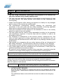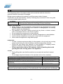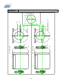
1
Motorised Sieve Shaker SV001 Impact Test Equipment Ltd www.impact-test.co.uk & www.impact-test.com User Guide User Guide Impact Test Equipment Ltd. Building 21 Stevenston Ind. Est. Stevenston Ayrshire KA20 3LR T: 01294 602626 F: 01294 461168 E: [email protected] Test Equipment Web Site www.impact-test.co.uk Test Sieves & Accessories Web Site www.impact-test.com CONTENTS Chapter 1 1.1 1.2 1.3 1.4 Chapter 2 2.1 2.2 2.3 2.4 Chapter 3 3.1 3.2 3.3 3.4 Chapter 4 4.1 4.2 Chapter 5 5.1 Chapter 6 6.1 6.2 6.3 6.4 6.5 6.6 6.7 6.8 6.9 6.10 Chapter 7 7.1 7.2 Chapter 8 8.1 Chapter 9 9.1 9.2 GENERAL INFORMATION GENERAL FEATURES IDENTIFICATION APPLICATIONS STRUCTURE AND OPERATING OF THE MACHINE SAFETY INFORMATION GENERAL SAFETY STANDARDS SAFETY SYSTEMS DANGEROUS PARTS AND RESIDUAL RISKS NOISE INSTALLATION LIFTING UNPACKING INSTALLATION ELECTRIC CONNECTIONS MACHINE FEATURES DIMENSIONS AND MASS OF THE APPLIANCE CHANGE OF THE VIBRATING INTENSITY OPERATOR INTERFACE CONTROLS AND MESSAGES USE WARNINGS SWITCHING ON OF THE APPLIANCE MACHINE TOOLING SPECIMEN POSITIONING TEST STARTING EMERGENCY STOP RESTARTING AFTER AN EMERGENCY STOP SWITCHING OFF FIRST TRIAL SWITCHING ON OPERATING EXAMPLE MAINTENANCE ROUTINE MAINTENANCE SPECIAL MAINTENANCE FAULT FINDING FAULT FINDING STORAGE AND DISPOSAL STORAGE DISPOSAL APPENDICES A B GENERAL VIEW OF THE APPLIANCE VIEW OF THE MOTOR WITH ECCENTRIC WEIGHTS -1- Chapter 1 1.1 GENERAL INFORMATION GENERAL FEATURES This manual is addressed to the carrier, the installer, the user, the maintenance operator, and the disposal operator. Please read it carefully because it contains information about the operation of the machine in safe conditions. This manual is to be considered a part of the product and relates only to the machine it is delivered with. Keep the manual in good order during the lifetime of the appliance for consultation. In case of sale, the manual should be supplied with the machine. The manufacturer assumes no liability for any damages caused by a misuse of the machine. The manufacturer has the right to modify this technical literature as well as the machines this refers to without any previous notice. Alerts: ATTENTION DANGER 1.2 Procedures that can seriously damage the machine if they are not followed carefully. Procedures that can be dangerous to the operator if they are not followed carefully. IDENTIFICATION SUPPLIER IDENTIFICATION: MACHINE IDENTIFICATION: 1.3 See the front page of this user guide See the plate on the machine where the complete identification data and electrical features are to be found. APPLICATIONS The SV001 Sieve Shaker has been manufactured for sieving tests on materials with a thin granulometry and for wet tests. It is suitable for site laboratory tests and eliminates the complexity of a hand sieving operation. This appliance should not be used for any other purpose other than that specified above.. ATTENTION The instructions given in this operating manual cover the correct use of the appliance. To carry out the test, the user must refer to specific applicable standards. -2- 1.4 STRUCTURE AND OPERATION OF THE MACHINE The appliance comprises a sieve holder plate with an electric motor fitted with eccentric weights; these eccentric weights turn and give the plate vertical sinusoidal vibrations. The appliance cannot hold more than eight sieves, plus lid and receiver. Sieves cannot be loaded with more than 6 kg of material. If further information is required please contact Impact Test Equipment. -3- Chapter 2 2.1 SAFETY INFORMATION GENERAL SAFETY STANDARDS The use, lifting, installation, maintenance and disposal of the machine are only to be carried out by suitably qualified staff. The user must learn about the operation of the machine to avoid misuse of it and the safety devices. Any safety devices must always be kept assembled and checked daily. Impact Test Equipment offers training and assumes no liability for any damages due to misuse of the machine by unskilled staff. The manufacturer recommends carefully following the instructions and procedures in this user guide and the safety standards concerning applicable safety devices and the general rules of the work environment. Verify the accordance of the machine to the standards in force in the country where the machine has to be installed. This user guide must be read by those responsible for safety, by the operators and maintenance engineers. It must be kept with the machine in order to be accessible at all times. Any tampering or modifications to the machine (electric, mechanical etc.) that have not been approved by written agreement from the manufacturer are not permitted and the manufacturer will not be liable for any damage caused by such modifications. The removal of or tampering with any safety devices will be an infringement of EEC Safety Standards. The manufacturer assumes no liability for any damages. The machine must be installed in a place free from the risk of fire and explosions. Only original spare parts and accessories are recommended; if other parts are used the manufacturer assumes no liability. Be careful to avoid dangerous situations during operation; immediately stop the machine if it no longer works properly and contact Impact Test Equipment. The manufacturer assumes no liability for any damage caused to people, property and animals if general safety standards or the instructions of this user guide are not followed. 2.2 SAFETY SYSTEMS Safety devices are all the safety measures using specific technical equipment (guards, cages etc.) to protect the operator from any danger that couldn’t be avoided when the appliance was planned. DANGER The removal of any safety devices or any tampering of the machine could cause risks to the operator or to any other people. ACTIVE SAFETY DEVICES All those devices avoiding or reducing the risks for the operators are active safety devices. These devices require an active and aware intervention to be operated. The switchboard has a main switch that can also be used as an emergency switch. -4- 2.3 DANGEROUS PARTS AND RESIDUAL RISK The dangerous place is the space inside and around the machine where the operator could be wounded or damaged. During some procedures the operator could face some risks of danger. These risks can be eliminated by carefully following the procedures in this user guide and using suitable safety devices. ATTENTION If Impact Test Equipment does not install the machine, employ only skilled operators trained for the lifting of heavy machinery. GENERAL INFORMATION Before starting to use the equipment, ensure that all the components are in good working condition and check there are no defective or damaged parts. If necessary repair or replace any damaged part. Pay attention to the risk of electric shock both by direct or indirect contact, due to unforeseen failure to the electric system. Do not subject the equipment to violent shocks. Do not expose the equipment to fire, extreme temperature or weld splatters. Avoid corrosive substances coming into contact with the equipment. Never wash the appliance using water sprays. DURING USE In order to ensure maximum safety for the operator, do not touch any moving components during the test and always use the proper safety devices. During the test always pay attention to the possibility of trapping hands, fingers or clothing in the moving parts of the equipment. Do not wear loose clothes, ties, watches, rings or jewellery that could get tangled in the moving parts of the appliance. LIFTING During lifting take care that the machine is securely held and that it cannot slide. Do not apply any kind of stress on the cylinders and on the crossbars. RISK OR DANGER FORESEEN SAFETY MEASURE FINGERS OR HANDS GETTING TRAPPED ABRASIONS – CUTS DAMAGE TO EYES CAUSED BY PROJECTING MATERIAL HEARING DAMAGE CAUSED BY EXCESSIVE NOISE REINFORCED GLOVES REINFORCED GLOVES SAFETY GOGGLES EAR DEFENDERS The manufacturer assumes no liability for any damage caused to people, property and animals if general safety standards or the instructions of this user guide are not followed. -5- 2.4 NOISE The indicated levels of noise are not necessarily safety levels for the operator. The exposure levels of the operator are obviously related to the emission levels of the appliance, but other factors influence the exposure levels as the time of exposure, the environment, and other appliances installed near to the appliance etc. The exposure levels permit to value the damages that could be caused by the noise. Acoustical pressure level equivalent Laeq at 1 mt. distance Acoustical power emitted by the appliance LWA Standard above data are referred DANGER 98 dB(A) 98 dB (A) EN ISO 3746 The continuous use of the machine together with other noisy appliances could cause a high level of exposure to noise. If the daily exposure of the operator is equal or higher than 85 dB(A), the use of safety devices such as ear defenders are suggested. If the daily exposure is equal or higher than 90 dB(A), the use of such a safety device is compulsory. For further information consult the standards of the country where the machine has been installed. -6- Chapter 3 INSTALLATION DANGER 3.1 Consult DANGEROUS PARTS AND RESIDUAL RISKS before proceeding LIFTING The operating instructions must be respected during the moving of the appliance and particularly in the following phases: Lifting and the storing First installation Further installations The machine is usually packed in a wooden case or in a carton that allows it to be moved easily. The machine must be moved by a forklift truck suitable for the weight indicated on the plate on the machine. The moving of cases with lifting devices must be made with required caution and following the indications given on the packing. Never use chains to lift the cases. 3.2 ATTENTION Pay attention to avoid impact and turning the equipment over ATTENTION Protect the machine from atmospheric agents. Water and humidity could oxidise it, causing serious damage. UNPACKING After removing the package, check that any parts of the machine are not damaged. In case of doubt, DO NOT USE THE MACHINE and contact Impact. DANGER 3.3 The materials used for packaging (plastic, polystyrene, screws, nails, wood etc.) must be kept away from children. They must be disposed of properly. ATTENTION Pay attention to avoid impact and turning the equipment over ATTENTION Before throwing away the packaging, ensure that no accessories, manuals, documents or spare parts are inside. INSTALLATION The machine must be placed in an environment suitable for the use it is designed for (laboratory protected by any atmospheric agents). A skilled operator must perform the installation. OPERATING TEMPERATURE OPERATING HUMIDITY O.S.L. MAXIMUM HEIGHT from + 5°C to + 40°C from 30% to 95% 1000 m -7- GENERAL RECOMMENDATIONS The machine must be installed so that it has free space on each side to allow for maintenance operations to be carried out. No authorised persons and no dangerous objects should be allowed near the machine. In order that the machine does not suffer displacement caused by vibration, the appliance has to be placed on a flat surface that is clean, without oil or grease. 3.4 ELECTRIC CONNECTIONS DANGER A skilled electrician must make the electrical connections. DANGER Before connection, see the attached electrical diagram and the plate on the machine for information about the voltage, frequency, etc. DANGER Connect the earth by the terminal PE (yellow-green) before making any other connections. DANGER Apply a knife switch at the top of the connecting cable of the machine to the power system. The knife switch must be combined with a safety device to protect from overload with a differential switch (safety switch). The technical features of the safety device must be in accordance with the standards in force in the country where the machine has been installed and following the machine features. ELECTRIC TOLERANCES: Real voltage 10 % of the nominal one Frequency: 1 % of the nominal one in a continuous way 2 % of the nominal one for a short period The harmonic distortion of the sum from the second to the fifth harmonics not more than 10 % of the total voltage as a real value between the conductors. A further distortion of 2% is accepted for the sum from the sixth to the thirtieth harmonics of the real total value between the conductors. With reference to the tension unbalance of the three-phase voltage, the inverted sequence component and the zero sequence component must not be more than 2% of the direct sequence component of the voltage The voltage pulses must not last more than 1,5 ms with an up/down time between 500 ms e 500 s and a peak value not higher than 200 % of the real value of the nominal tension. The electric feeding must not be interrupted or zeroed for more than 3 ms. Between two interruptions it must not take more than 1 s. The interruptions must not overcome 20 % of the tension peak for more than one cycle. Between two interruptions it must not take more than 1 s. -8- Chapter 4 4.1 DIMENSIONS AND MASS OF THE APPLIANCE LENGTH WIDTH HEIGHT WEIGHT 4.2 MACHINE FEATURES 343mm 411mm 1180mm 24 kg CHANGE OF THE VIBRATING INTENSITY The sieve shaker is designed to work with two different vibration intensities: high intensity and low intensity. The instrument is originally set on the low intensity, but if required high intensity can be obtained by changing the position of the vibrating weights on the motor shaft (see appendix B). As one can see the eccentric weight has two different holes: one is positioned at 28mm from the edge and another one at 21.5mm. from the edge. The first hole positioned at 28mm corresponds to the low intensity and is the hole, where the motor shaft is introduced. The other one (at 21.5mm) corresponds to the high intensity vibration. To go from low to high intensity the hole on the motor shaft must be changed. It must go from the hole at 28mm. from the edge to the other one at 21.5mm. from the edge. Below is the procedure for changing the vibration intensity of the shaker: 1. Unscrew the fixing screw (B4) from the eccentric weight (B5) to the motor shaft (B3). 2. Unthread the eccentric weight from the hole (B1) it is assembled to the motor shaft. 3. Assemble the eccentric weight on the other hole it has and screw the fixing screw. See Appendix B -9- Chapter 5 5.1 OPERATOR INTERFACE CONTROLS AND MESSAGES See Appendix A A1 CROSSBAR LOCKING HANDLES For locking the crossbar into place against the sieves, locating them strongly to the sieve holder. A2 CROSSBAR CLOSING THE SIEVES Locates the sieves against the sieve holder. A3 THREADED BARS For setting the crossbar height. A4 FIXING NUTS FOR THREADED BARS To fix the threaded bars to the sieve holder. A5 SIEVE HOLDER The base on which a series of sieves is placed according to requirements. A6 SUPPORTING FEET Allow the sieve shaker to be placed strongly on any king of supporting surface. A7 MAIN SWITCH For turning the sieve shaker on and off. A8 TIMER Selection of the sieving time from 0 to 60 minutes. - 10 - Chapter 6 USE DANGER 6.1 Consult DANGEROUS PARTS AND RESIDUAL RISKS before proceeding. WARNINGS Before starting the normal use of the equipment it is recommended to verify that it is in good working conditions with no defective or damaged parts. If necessary proceed with the required maintenance operations 6.2 SWITCHING ON OF THE APPLIANCE Put the main switch on “I” 6.3 MACHINE TOOLING Below we describe some “standard procedures” allowing even a less experienced operator to complete a correct tooling up of the sieve shaker. INSTALLATION OF THE THREADED BARS If these were not in position, screw the threaded bars (A3) to the sieve holder (A5) following the instructions given below: 1. Thread the bars (A3) in the foreseen positions on the sieve holder (A5) 2. Stop the threaded bars (A3) using the fixing nuts (A4). 3. Position the crossbar (A2) at the wished height on the threaded bars and block it using the blocking handles (A1). See Appendix A PREPARATION OF THE SIEVES The SV001 can receive mesh sieves and sieves with perforated plates having 200250-300-315 mm and 8”-12” diameter. The sieves must be placed as follows: 1. Place the receiver in its place on the sieve holder of the sieve shaker base. 2. Add the sieves paying attention to the order, starting with the smaller apertures on the bottom and continuing with the larger apertures on the top. 3. At the end add the lid and fix the series of sieves strongly using the blocking crossbar (A2) introduced into the threaded bars that are placed on the sieve holder. The system of placing sieves and the blocking crossbar gives the possibility of also fitting a receiver and a lid for wet sieving tests. ATTENTION Before any kind of tooling up action on the sieve shaker be sure that the main switch is positioned on “0”. - 11 - ATTENTION 6.4 Before proceeding with the normal use of the appliance ensure that all the parts composing the appliance are properly tooled up and are suitable for the test they have to make. SPECIMEN POSITIONING ATTENTION Before proceeding with the normal use of the appliance ensure that the sieves installed on the appliance are suitable for the specimen that has to be tested (check on the chapter “MACHINE TOOLING”). The positioning of the material to be tested can be made in many different ways depending on the kind of test to be carried out. For the correct preparation of the materials check the standards applicable to the test to be carried out. 6.5 TEST STARTING Set the timer to the sieving time required and put the main switch on “I“. 6.6 EMERGENCY STOP In case of emergency the test can be stopped immediately by positioning the main switch (A7) on position “0”. ATTENTION 6.7 Please remember that a sieving interruption could give wrong results for the test and the operator may have to cancel the test. RESTARTING AFTER AN EMERGENCY STOP DANGER Before starting the appliance again, find and eliminate the problem, which caused the need for an emergency stop. To start the appliance again turn the main switch (A7) on position “I”, this will start the normal operation of the sieve shaker again. 6.8 SWITCHING OFF Once the test cycle is finished, follow the instructions below to turn off the appliance: 1. Switch off the appliance by turning the main switch (A7) to the position “0”. 2. Remove all the sieves and carefully clean the shaker. 6.9 FIRST TRIAL SWITCHING ON Before beginning regular use of this machine, check it is working perfectly by performing at least one complete trial cycle according to the instructions given above. In case of problems during this test cycle, see the Chapter entitled “ FAULT FINDING “. If none of the instructions given in this user guide solve the problem, please contact Impact. - 12 - 6.10 OPERATING EXAMPLE Below we describe some “standard procedures” allowing even a less experienced operator to complete a correct tooling up of the sieve shaker. 1. Tool up the sieve shaker properly as explained in the chapter “MACHINE TOOLING” of this operation manual. 2. Turn the handle of the timer to the sieving time required. 3. Turn on the appliance, positioning the main switch on “I”. Once the sieving time has passed the appliance stops and the test is finished. Now the main switch must be turned on “0”. For other tests please follow the above procedure. - 13 - Chapter 7 7.1 MAINTENANCE DANGER Consult "DANGEROUS PARTS AND RESIDUAL RISKS” before proceeding. DANGER All the maintenance operations must be carried out with the machine turned off and unplugged from the knife switch. DANGER Skilled operators instructed on the purposes the machine is designed for must carry out any kind of maintenance operations involving the mechanical components of the machine and electric components, even those which may seem very simple. DANGER Only original spare parts are allowed. The Manufacturer assumes no liability in the event that other parts are used. ROUTINE MAINTENANCE In order to maintain good working of the machine for a long time, periodically clean all the parts and oil the parts that are not painted. Do not use solvents, which may damage the paintwork and parts made of synthetic materials. After each test, check that all parts of the shaker are undamaged. If something is damaged please contact Impact. 7.2 SPECIAL MAINTENANCE In case of special maintenance operations (repairs, replacement of parts and any other operation not described in this manual) please contact Impact. - 14 - Chapter 8 FAULT FINDING Some easy to solve and simple problems, which can happen during the working of the shaker, are introduced in this chapter. ATTENTION All maintenance, checking, control and repairing operations of each part of the machine or of the electric system, must be carried out by skilled operators instructed in the functions and working procedures of the appliance. PROBLEM POSSIBLE CAUSE Sieve shaker doesn’t start after No supply activation of the Main switch Damage to the motor Damage to the electric installation The fuses have blown ATTENTION ACTION Check that the plug is properly plugged to the main. Contact Impact Contact Impact Contact Impact to proceed with the proper replacement of the fuses. Contact Impact for any other kind of problem that is not described in the above table or in case the problem continues after the suggested action above. - 15 - Chapter 9 9.1 STORAGE AND DISPOSAL STORAGE 1. In the case of long-term storage it is necessary to disconnect the electric supply. 2. Carry out all maintenance operations. 3. Lubricate non-painted parts with some oil. Cover the machine to protect it from dust and moisture. 9.2 DISPOSAL When the machine is no longer used, the following is recommended: 1. Disconnect the feeding cable. 2. Cover/destroy all the parts which may be dangerous as cutting, projecting or sharpened ones. 3. Disassemble the machine and scrap it as per the actual laws. - 16 - APPENDIX A GENERAL VIEW OF THE APPLIANCE A1 A2 A3 A4 A5 A8 A7 A6 - 17 - VIEW OF THE MOTOR WITH ECCENTRIC WEIGHTS - 18 - B4 B3 HIGH VIBRATIONS B4 LOW VIBRATIONS B3 B2 B5 B1 B2 B1 B5 APPENDIX B