1
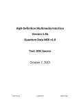
Using HDMI Guide. A technical briefing by J. S. Technology. 1. 2. 3. 4. 5. 6. 7. 8. 9. 10. 11. 12. 13. 14. 15. 16. 17. Introduction. ___________________________________________________________________1 Does it Have To Be HDMI? _______________________________________________________ 1 Which Version of HDMI? ________________________________________________________ 2 HDMI Cables – Which to buy? ____________________________________________________ 3 HDMI Version Number Verses Standard and High Speed Leads. __________________________ 4 HDMI – Long Lengths.___________________________________________________________ 5 HDMI Switching. _______________________________________________________________ 6 Multiple Displays. _______________________________________________________________ 7 Multiple Inputs and Multiple Outputs. _______________________________________________ 7 The Pitfalls – Multiple Displays. ___________________________________________________ 9 An Alternative – Convert HDMI to HD Component Video (YUV / YPbPr). ________________ 11 3D TV and HDMI. _____________________________________________________________ 12 The Mixing of 3D with HD Audio. ________________________________________________ 12 3D with Multiple Displays. _______________________________________________________ 14 Future Technologies and HDMI Alternatives. ________________________________________14 Conclusions. __________________________________________________________________16 References. ___________________________________________________________________18 1. Introduction. HDMI is the new SCART connector. An all-in-one connector covering both video and audio interfacing between your A/V source and display. It promises HD video and audio, and the very latest versions also include networking. Yet, HDMI isn’t without its problems. Multi-display environments often highlight the complex nature of HDMI and its incompatibilities. In HDMI’s short life there have already been several versions. Recently support for 3D TV has been added creating further incompatibilities with existing hardware. Then there’s HDCP, the copy protection system, which is often blamed for preventing the smooth operation of an audio / visual system. In this guide we’ll cover some of the connection methods and the drawbacks of HDMI. 2. Does it Have To Be HDMI? This may be a strange question to ask in a guide to HDMI. However, this is an important question. HDMI has been seen as the connector for “HD” or High Definition video, yet before HDMI there was component (YUV / YPbPr) and also DVI connections. In the professional video world there is also the SDI interface, see Figure 1. Each of these connection types gives similar results [1]. As we will see later there are other means in which to connect HD video to a display. Using HDMI Guide. © J. S. Technology Ltd. 2012. Page 1 Component Video, typically three phono / RCA connectors. DVI Connector. HDMI connector. SDI is carried by co-ax cable, and terminates on a BNC connector. Figure 1. Several types of connection for High Definition Video. HDMI has been promoted for domestic use because it is a closed system. It has within it HDCP, a means to restrict the use of the HD content. Not only does the HDMI have this “protection” but also licensing terms enforce manufacturers of video sources that include HDMI to restrict the resolution of other outputs [2]. Therefore, the consumer is not given a free choice of which connection scheme to use but is forced to use HDMI. Displays and sources which were HD compatible before the HDMI connector, or had additional outputs, are being made obsolete by these conditions. HDMI has in place key restrictions which seem monopolistic. Therefore in a consumer video situation the answer is: YES; it has to be HDMI. 3. Which Version of HDMI? HDMI has been developed in the public eye. Version 1.4 is the latest, but 1.2 and 1.3 devices are common (Table 1). Although backward compatibility is claimed for HDMI, as we’ll see below with 3D this is not always the case. It could be argued that the end user is expected to upgrade their products to cope with each iteration of HDMI. Full Resolution 1080p 192kHz 24 bit audio DVD Audio Support Super Audio CD Deep Colour Auto Lip Sync HD Audio Stereoscopic 3D Ethernet Channel V1.0 V1.1 V1.2 V1.3 V1.4 Table 1. HDMI versions and their salient features [3]. A brief description of each of these features is given below: Full Resolution 1080p – The typical resolution for Blu Ray and games consoles. 192kHz 24 bit audio – This defines the included audio stream within the HDMI feed. DVD Audio Support – A new type of CD audio for improved sound quality. Super Audio CD – A new type of CD audio for improved sound quality. Using HDMI Guide. © J. S. Technology Ltd. 2012. Page 2 Deep Colour – The ability to show a larger range of colours using a higher precision numbering system. Auto Lip Sync – To automatically adjust for delays between audio and the displaying video. HD Audio – Support for Dolby TrueHD and DTS-HD Master Audio. Stereoscopic 3D – Defines 3D modes. (HDMI V 1.3 has also been shown to support 3D.) Ethernet Channel – Network interface between connected devices. Note: The stated compliance with a version does not imply that all features are available! For example, a V1.4 device may not have the Ethernet channel included. 4. HDMI Cables – Which to buy? There can be no justification for over spending on HDMI leads. When dealing with digital signals you get the same information on an inexpensive cable as you do on highly advertised and expensive branded cable. It’s similar to sharing digital photos from one mobile phone to another. It’s made a digital pathway from phone to phone through the ether, and yet the picture is identical. Same with HDMI; it’s a digital connection. An inexpensive cable need not be a poor quality one. To illustrate that an inexpensive unbranded lead will give an identical picture to an expensive branded lead an experiment was carried out. Using a well-known brand against an old and unbranded lead. The branded lead is the very latest HDMI 1.4 compliant lead with the Ethernet channel, whereas the unbranded is one of the oldest that could be found. Both are 2m long. The source was a Blu Ray player connected to a plasma screen. Both tests were conducted at 1080p, and verified to be at 1080p. Each picture was taken on a DSLR camera, and has only been cropped by GIMP to remove the excess boarder. No other image manipulation has been performed. Figure 2 shows the resultant images. As can be seen from the images below there is no difference in results from the two leads tested. The expensive highly advertised branded lead gives a clear and vibrant pictures, however, so does the inexpensive unbranded lead. With longer leads it’s more likely that missed edges of the HDMI signal will impact on the image as small white dots, also known as “sparkles”. Or the lead may simply not work at all, but that same lead may work in another system. It then becomes dependent upon the source and display equipment. No guarantee can be offered by the manufacturers of the source or display, or indeed the lead, that a certain length will work. See the next section for an alternative solution. Longer lengths are also made from thicker cable than shorter ones, therefore it may be more difficult to route the lead neatly. Costs for these longer leads do increase but it is still not a justification to opt for an expensive highly advertised brand. J.S. Technology deliberately doesn’t stock branded cables for HDMI in the firm belief that they offer no advantage to the customer. Only quality unbranded leads that have been tested and proven in a real world home-cinema are stocked. Using HDMI Guide. © J. S. Technology Ltd. 2012. Page 3 Inexpensive unbranded lead. Highly advertised branded lead. Figure 2. Comparison between two different leads and the resultant imagery. 5. HDMI Version Number Verses Standard and High Speed Leads. As discussed in a previous section there have been a number of different versions of HDMI. Since a lead just creates a data link the minor differences between some versions of HDMI cannot affect picture quality. Various companies have, however, used the introduction of a new HDMI version number to release a new range of leads suggesting a requirement to also upgrade the leads when upgrading other parts of the system. Yet, as demonstrated in the previous section, even the very latest V1.4 lead gave the same picture as an old pre-V1.4 lead. In a move claimed to bring clarity to the HDMI lead market the HDMI Licensing LLC company have created new classifications for HDMI leads to adhere to. For those who license from HDMI they must not use an HDMI version number for the leads but rather these new classifications. The salient ones for home use are: Standard HDMI Cable. High Speed HDMI Cable. Standard HDMI Cable with Ethernet. High Speed HDMI Cable with Ethernet. Using HDMI Guide. © J. S. Technology Ltd. 2012. Page 4 “Standard” is considered to be a picture of 720p, 1080i or lower, without Deep Colour. “High Speed” is able to handle all resolutions including 1080p and 3D. The option of “with Ethernet” is required where an internet connected device is to be used via the HDMI lead, although many devices have their own direct connection to the internet. For example a Blu-Ray player will have a LAN port for direct connection to the internet to enable the BD-Live service. While it is internet enabled, it does not necessarily mean that a “Cable with Ethernet” is required as it may not be utilising the HDMI system for networking. Since most home systems will already be operating at 1080p the leads will already be “High Speed”. Only where a system will specifically use the HDMI Ethernet channel will leads have to be upgraded as this is a new feature that was not supported previous to V1.4. [4] 6. HDMI – Long Lengths. HDMI leads up to 25m can be found, but are rare and costly. Generally it’s considered that 10m is a safe limit for HDMI. For longer lengths another means for transporting the HDMI signal should be considered. The most common solution is an HDMI to CAT5e / CAT6 converter, as shown in Figure 3. Distances of up to 60m at Full HD have been claimed, with CAT5e / CAT6 cabling costing as little as 20p per metre [5]. An example of an HDMI to CAT5e / CAT6 Interface and its use. Figure 3. An alternative solution for transporting HDMI over longer distances. These devices will allow the HDMI signal to be carried over inexpensive CAT5e / CAT6 cables, as used in computer networking. At the source there is a small box to convert the connection from HDMI to an RJ-45 network type connection, where the CAT5e / CAT6 cables will attach. On the distant receiving side is a similar box converting the signal back to an HDMI connector. Operation of these is typically transparent to the user. CAT5e and CAT6 are types of cable used in computer networks. They’re terminated in an RJ-45 connector, as shown in Figure 4 below. Most PCs and laptop computers will have a socket for a LAN interface using this type of connector. Although the connections are the same, HDMI over CAT5e / CAT6 systems should not be connected to a computer network but have their own dedicated cables. Using HDMI Guide. © J. S. Technology Ltd. 2012. Page 5 An RJ-45 connection on a CAT5e/CAT6 network lead. Figure 4. A typical network connection. 7. HDMI Switching. With so many different sources all using HDMI there simply isn’t enough inputs on a TV, and worse for other display types such as projectors. There has to be a means to switch these sources. Simple switches, Figure 5, act upon the most recent active source to automatically switch over. Others require the user to switch using an IR remote control, Figure 6. Two input HDMI switch. Automatically switches to the most current active input. Figure 5. HDMI switching for two sources. Four input HDMI switch. Controlled by via remote control. Figure 6. HDMI switching for four sources. Using HDMI Guide. © J. S. Technology Ltd. 2012. Page 6 8. Multiple Displays. Although without doubt HDMI has been designed as a single ended system, where one source is connected to one display, it is possible to use “splitters”. This is a very bad term as the signal isn’t split at all! Rather the input signal is regenerated and passed to each individual output as a fresh copy. As the information is digital there is no loss in quality when creating these copies. In Figure 7 there are two examples of HDMI splitters, one for connecting two displays and another for four. Ideal applications for these would be where there is a flat screen TV for general viewing and a projector for occasional use. Top images:1 to 2 outputs. Lower images: 1 to 4 outputs. Figure 7. Distributing HDMI to multiple displays. 9. Multiple Inputs and Multiple Outputs. There are three types of device that have multiple inputs and outputs. Firstly there are switches which also incorporate a splitter within the one unit. Secondly there are “cross-over” switches where each output can be connected to an individual input, but no two on the same input as they lack the splitter functionality. Finally there are “Matrix” switches which can further allow any of the inputs to be routed to any of the outputs to show the same or different source. When a switch is combined with a splitter it performs both functions in the one unit. Firstly it is able to select between each of the inputs to the unit, and secondly display this selected source to all its outputs. This is shown in Figure 8 where there are four different sources, but only one switching circuitry outputting to a splitter which then drives the two displays. Using HDMI Guide. © J. S. Technology Ltd. 2012. Page 7 HDMI Switch with integrated Splitter. Both output displays show the same picture (pink). Figure 8. HDMI switch whose output also includes a splitter function. A “cross-over” switch is one where each of the outputs can individually be connected from any of the inputs. In effect a cross-over switch is built from multiple switches all in the one unit. There is a significant limitation with cross-over switches in that each output must have a unique input selection and cannot both be connected to the same source at the same time. It does not have any splitter functionality. In Figure 9 the first output, display 1, is connected to the first source (pink) just as the previous example. Because of the limitation that no two outputs can select the same source the second display, display 2, has to be changed over to a different input, in this case source 3 (yellow), but it could have equally been source 2 (tan) or source 4 (green). Cross-over switches allow each output to select a unique input. Figure 9. A type of HDMI switch with multiple switching circuits. The third device type is the “matrix” switch. It combines the features of both the switch with splitter and cross-over switches in to one unit, allowing for each output to select an input which is either different from or the same as any other output. It is more complex than the previous examples, with multiple switching circuits and multiple splitters inside the one unit. The left hand example of Figure 10 replicates the switcher with splitter function where both outputs are able to display the same input. In the right hand example, using the same connections as previously, each display is able to select a different source similar to the way the cross-over switch would work. The advantage with a matrix switch is the flexibility that it offers to select any input for any output. Using HDMI Guide. © J. S. Technology Ltd. 2012. Page 8 Both switches are set to the same input source; therefore both displays show the same (pink). Top switch selects source 4 for display 1 (green). Lower switch for display 2 selects source 2 (tan). Figure 10. Matrix switching where each switch can select any source without prejudice. An example of a Matrix switch is shown in Figure 11 for 4 inputs with 2 outputs. On the rear are the two output HDMI connectors, and a group of four input connections. The front display has indicators to highlight which input has been selected. This type of unit is supplied with an IR remote control, but also has two front mounted selection buttons. Matrix switch with four inputs and two outputs. Figure 11. An example of a Matrix switch. 10. The Pitfalls – Multiple Displays. It would seem that HDMI was conceptualised from the very start as being a single source to a single screen. Much like DVI for PCs where the source (PC) is under the desk of the monitor, and that only one monitor would be driven off that single connection. However, in a home environment it’s not uncommon to have multiple screens driven off the one source: Main living room TV. Bedroom TV. Kitchen TV. Projector for movies or sports. HDMI only outputs one video stream, and that is of a certain resolution. Therefore, all the screens must support that same resolution otherwise it will default to the highest common resolution. This may mean Using HDMI Guide. © J. S. Technology Ltd. 2012. Page 9 that in the main living room the TV won’t receive the 1080p signal it can handle because the bedroom TV can only accept 720p. There is also a common misunderstanding when a TV is marked as “HD Ready” as it then can only accept 720p or 1080i resolutions. A “Full HD” or “Full 1080p” screen will be able to accept 1080p. Unfortunately there is no standard which guarantees that the HD screen is indeed one which is able to accept 1080p and the best advice is to look for a “1080p” marking on the screen or in the TV’s specifications. The examples below in Figure 12 show how a mixed HD Ready and Full HD screen will operate. When the higher resolution screen of a Full HD model is mixed with a lower HD Ready screen the system will select the highest common resolution. This resolution will either be 1080i or 720p and not 1080p. Only when the Full HD screen is mixed with a similar one will it be able to display the full 1080p picture. In this example we’re showing the HD Ready with a 720p picture as this is its natural resolution. Often the screen will select 1080i, an interlaced mode, as its default resolution. It is suggested that if the source is able to run as high as 1080p then it’s best to change this to 720p for use with an HD Ready display. This is because it will better match the displayable lines than allowing the sources to automatically select 1080i as they will typically do. Often it is sufficient to switch off the HD Ready screen when only wishing to view on the Full HD screen at 1080p. It’s not uncommon, however, that the output video resolution settings in the source have to be readjusted again to 1080p. With mixed HD Ready and Full HD screens the resolution defaults to the most compatible resolution, which is lower than the Full HD screen can display. When two Full HD screens are mixed it is possible to run both at the full 1080p resolution. Figure 12. The difficulties in mixing displays of different resolutions. Further, there are just simple incompatibilities. It may not be possible for whichever splitter that you choose to share the HDMI to find a common and compatible screen resolution. It’s been observed that even just routing from one source, through a switch, to a screen for the source to default to a lower resolution than is possible with a direct connection. Or in some situations, the HDCP protection system will not allow content to be displayed. In these cases it is an incompatibility in the source, the screen, or even the splitter itself. There is diagnostic equipment which will help establish the actual cause, but it is expensive and not simple to use [6]. For an end user updating each of the source’s firmware is the best advice, and trying alternative splitters. If this fails then the displays or sources may have to be replaced. Using HDMI Guide. © J. S. Technology Ltd. 2012. Page 10 11. An Alternative – Convert HDMI to HD Component Video (YUV / YPbPr). Not every display has an HDMI connector but they may have another high quality input – the YUV / YPbPr Component video input. How does one change HDMI to YUV? The solution is to use an HDMI to YUV / YPbPr Component video converter, Figure 13. Both HDMI and YUV Component video are similar in terms of quality, so with a high quality video converter there will be no degradation in picture quality. Additionally due to the complex nature of HDMI in muti-display environments it’s sometimes more desirable to use YUV / YPbPr component video where there are few problems with distributed video. For this very reason some professional installers prefer to convert HDMI to YUV to ensure compatibility for their clients. HDMI Input. YUV / YPbPr and audio Output. The HDMI to YUV / YPbPr Component Video Converter. Figure 13. An alternative to solving incompatibilities with HDMI. In addition to HDMI to Component Video converters there are other options. Conversion to DVI is possible, but this will typically only allow for a PC monitor to be used. Using DVI will typically maintain HD video resolutions, but in some cases it’s a standard definition signal that’s required. It may be desired to connect and HD source with a standard definition TV or even data projector where HDMI or component video isn’t available. For that the options are to convert HDMI to either SCART, S-Video or Composite video. An example is converting Apple TV, which only has an HDMI output (V2 and V3), to a normal TV. Two such converters are shown in Figure 14. HDMI to SCART Converter. HDMI to S-Video and Composite Converter. Figure 14. Two solutions to connecting HDMI to standard inputs. Using HDMI Guide. © J. S. Technology Ltd. 2012. Page 11 12. 3D TV and HDMI. Cinemas have had a resurgence of 3D projection, with some of the biggest films recently being in 3D. Even some older films are being re-mastered and released in 3D [7]. With films being produced in 3D an outlet for the home was the next obvious step [8]. Initially HDMI did not support 3D, but some HDMI V1.3 devices were seen to start supporting 3D content in a limited fashion. With HDMI V1.4 a much larger range of 3D resolutions and modes are supported within the standard [3]. However, there are two serious issues that have been discovered by professional installers and others: 1. Audio being routed via an external amplifier. 2. Multi display systems. These will be covered in the next sections. 13. The Mixing of 3D with HD Audio. Remember that HDMI carries audio as well as video. The HDMI must then be routed via an amplifier to gain access to the audio streams, and especially the HD audio content (see Figure 15). This creates a problem that the amplifier may not understand the 3D video signal, which results in amplifier switching off the 3D video stream. It then leaves the viewer with a choice of having no 3D but HD audio, or 3D picture but no HD audio. Neither case is satisfactory. Routing HDMI via a non-3D aware external amplifier to use the audio information contained within the HDMI stream. Because the amplifier is not 3D aware it will refuse to accept 3D video, resulting in only 2D imagery on the screen. Figure 15. How HDMI with 3D and HD Audio conflicts when not all systems are 3D compatible. Using HDMI Guide. © J. S. Technology Ltd. 2012. Page 12 Before HDMI this wouldn’t have been a problem as digital audio was carried separately via the TosLink system (either an optical or an electrical connection). It would also have been easy to “split” or buffer the video or audio between both the amplifier and the screen. However, even if we tried an HDMI 1 to 2 splitter this would fail. The HDMI system would still default to the non-3D picture. It is expected that the owner changes the amplifier to a newer model just to support the 3D video stream, in addition to already having to upgrade their sources and screen. Fortunately some models of Blu-Ray players have adapted to this issue and are now supporting dual HDMI output connections, with one for video and one for audio. One example is the Panasonic BMP-BDT310, whose connections we show in Figure 16. The “MAIN” HDMI output would carry the 3D picture to the screen, with audio being routed to the amplifier via the “SUB” HDMI output. Even with this solution other control functions have to be switched off to allow for the output audio to be forced into HD mode. Rear of a Panasonic Blu Ray Player. Note – Dual HDMI output (Highlighted). [9] Figure 16. Some HDMI sources have resorted to using multiple outputs to avoid incompatibilities. When using a source with two HDMI outputs, such as the one discussed above, the “sub” HDMI feed goes directly to the amplifier for HD Audio and the “main” feed for picture goes to the screen. The diagram in Figure 17 details how to connect these up. It is typical that the “sub” or audio output HDMI has also a basic low resolution picture included. Although not shown, it is common to also have a connection from the amplifier to the TV to allow for the setting up of the amplifier and to adjust the audio levels of the surround sound speakers. How to use a 3D source with Dual HDMI outputs. One output is dedicated for 3D video while the other contains the audio with a low resolution 2D image. Figure 17. 3D imagery and HD Audio are being connected separately to avoid incompatibilities. Using HDMI Guide. © J. S. Technology Ltd. 2012. Page 13 14. 3D with Multiple Displays. Splitting the HDMI between a 3D screen and a 2D screen also causes problems. Similar to the previous example where difficulties arise when sharing HDMI between screens of different resolutions, the HDMI will default to a 2D picture. Other than disconnecting the 2D screens there currently no known effective solution to maintaining a 3D picture. 15. Future Technologies and HDMI Alternatives. The future for HDMI is very reactionary and will depend upon any new technologies or developments both from the world of cinema and consumer electronics. With the latest HDMI standard there is an increase in resolution with 4k (4,096 x 2,160 at 24fps) images a possibility. This is one of the standards for digital cinema [10] but as of yet there are no known sources of material for home consumption. However, digital cinema may in future opt for higher frame rates beyond what HDMI is currently capable of. An increase in frame rate would most likely once again require another iteration of HDMI to support faster data rates than currently supported. If anything, the history of HDMI has shown is that it’s not a future proofed technology. For screen display interfacing perhaps the most important interface right now is the network connection. With an ever increasingly connected world there is without a doubt demand for TVs to be connected to the internet [11]. Be it WiFi or Ethernet, TVs are already becoming aware of the internet, and with newer models also supporting hard drives, it’s clear that movie rentals streamed over the internet and stored on a local drive is the future. In a world of internet TVs the notion of an external player containing the source material that then requires a video connection to the screen doesn’t exist; the TV is its own combined source and display [12]. WiFi and Ethernet cables are common in the modern home. Figure 18. WiFi and LAN interfaces. An “internet TV” typically has an Ethernet connection with the option of WiFi and both of those interfaces are well known technologies (Figure 18). There is already sufficient infrastructure within many homes to allow for a TV to be easily connected to the internet. Adding an internet TV does not require other items to be upgraded as it can do with HDMI. DisplayPort has also been proposed as an alternative to HDMI. Without the restrictive licensing terms of HDMI for manufacturers it’s a more desirable proposal, certainly in PC terms, than DVI. One major advantage of DisplayPort is the ability to drive a number of monitors off a single connection. It is able to display the same image on a number of monitors, or a different image over various monitors [13]. As it Using HDMI Guide. © J. S. Technology Ltd. 2012. Page 14 stands DisplayPort already supports 4k video resolution, deep colour, and 3D. This type of connector, shown in Figure 19, will probably remain only on PCs. DisplayPort logo and typical cable. Figure 19. An alternative PC monitor interface. Apple and Intel have jointly worked on a new type of interface, called Thunderbolt [14]. It is intended to be able to offer exceptionally high speed connections with multiple devices connected to the Thunderbolt “chain”. It combines PCI-Express with DisplayPort to allow for both monitors and external PC equipment, such as hard drives and networking, to be easily connected. As with DisplayPort, Thunderbolt can drive a number of external monitors, not just a single one, at high bandwidth. Thunderbolt logo and typical cable. Figure 20. A new type of display interface with the ability to connect other types of peripherals. Thunderbolt can have up to 7 devices daisy chained off the one source, but with the use of external hubs this can be extended further. Thunderbolt can be carried on either copper wires, Figure 20, or optical fibre, with the latter able to transport over many tens of metres. If Apple were to release a TV it would certainly be supplied with Thunderbolt. At the moment only displays designed for computer use have so far been equipped with Thunderbolt. There is sufficient capacity within Thunderbolt for future technologies to be carried on this interface. Multiple monitors could be the next logical progression for games consoles, following where games PCs have already progressed [15]. Multiple monitors have been used in flight simulations to give a separate instrument display from that of the flight path, but are also now being used to give a more complete surround view for other types of games. The example in Figure 21 shows a car racing game being played. HDMI doesn’t have the native ability to connect up multiple monitors, whereas DisplayPort and Thunderbolt already have this within their standard. Using HDMI Guide. © J. S. Technology Ltd. 2012. Page 15 Three monitors offer surround viewing capability. This example is for car racing, but flight simulation and role playing are also possible. Figure 21. Multiple monitor gaming example featured on http://multimonitor.net. Future games consoles may opt for DisplayPort or Thunderbolt to offer native multiple display support. There are simple adaptors to allow these types of connection to be converted to HDMI for backward compatibility; therefore there is no need for HDMI to be offered on the consoles too. 16. Conclusions. The consumer has been forced to use HDMI and with it face various incompatibility issues. While a single source to one display typically doesn’t have any problems, mixing various sources and multiple screens can raise serious questions on the viability of HDMI as a standard. Further, the new breed of 3D TVs has shown more limitations and incompatibilities in HDMI. Some source manufacturers have been forced to provide multiple HDMI outputs as a work-around for these problems. It’s been shown that the need for expensive highly advertised branded leads simply doesn’t exist as an inexpensive unbranded lead will give the same quality of picture. This is because the link is digital and both types of leads carry exactly the same information. For long cable lengths HDMI simply isn’t as robust as the previous HD component video standard. Where lengthy runs are required it is advisable to convert HDMI to run on CAT5e/6 network cabling instead as this offers easier cable management and reduced costs compared to long HDMI leads. Multiple sources and multiple displays can cause issues with a lack of inputs on a screen, and the splitting of the HDMI signal. Care should be exercised when selecting either switchers or splitters. Often just trying a different switch or splitter can help. Although no guarantee of compatibility can be given it is best to buy from a company who tests for real-world compatibility with a range of sources and screens such as J.S. Technology Ltd. It may be that the best means to overcome incompatibilities within the HDMI standard for splitting and distribution is to convert to an alternative format such as component video (YUV / YPbPr). HD video is supported, with fewer problems when distributing, switching, or using longer cable lengths. With a source which offers an HDMI output but lack a standard video outputs, such as Apple TV V2 & V3, Using HDMI Guide. © J. S. Technology Ltd. 2012. Page 16 video converters are available from J.S. Technology which make the connection to a standard display possible. See our guide to connecting Apple TV V2 & V3 [16]. For PCs the DisplayPort and Thunderbolt interfaces offer a better connection scheme more in keeping with their needs. Multiple displays, and the ability to connect many different types of equipment via Thunderbolt is an exciting prospect. Even more exciting would be for future games consoles to make use of the ability to drive multiple displays for immersion gaming. In the future domestic audio / visual equipment may all be simply connected to the internet, with music, films and TV shows all streamed directly to the TV. An internet connected TV uses the current networking infrastructure that is already available in most homes. In that future there is no need for HDMI. With limited ability to future proof any HDMI installation the advice can only be to choose the most appropriate switches, splitters, converters and leads required at the time. It must be accepted that an upgrade may be required at a later date as the HDMI standard evolves, or when new sources or displays are purchased. Therefore, the choice of which HDMI accessory to add to a system is dictated by the immediate requirements of the system. Using HDMI Guide. © J. S. Technology Ltd. 2012. Page 17 17. References. [1] “DVI vs. HDMI vs. Component Video -- Which is Better?,” February 2005. [Online]. Available: http://www.ecoustics.com/electronics/products/articles/122868.html. [2] “What is HDCP?,” [Online]. Available: http://www.digitalconnection.com/faq/HDTV_12.asp. [3] “HDMI #Versions,” [Online]. Available: http://en.wikipedia.org/wiki/Hdmi#Versions. [4] J. Knott, “When Do You Need High Speed HDMI?,” Electronic House, January 2010. [Online]. Available: http://www.electronichouse.com/article/when_do_you_need_high_speed_hdmi/. [Accessed April 2012]. [5] “CAT6-CCA C6 UTP Ethernet Network SOLID Cable Reel Box Wire 305m,” Kenable, [Online]. Available: http://www.kenable.co.uk/product_info.php?products_id=4172. [Accessed April 2012]. [6] Quantum Data, 20112. [Online]. Available: http://www.quantumdata.com/. [7] “Titanic Movie,” Twentieth Century Fox, 2012. [Online]. Available: http://www.titanicmovie.com/. [Accessed 2012]. [8] “Quality warnings issued over 3DTV,” BBC, June 2010. [Online]. Available: http://www.bbc.co.uk/news/10446419. [Accessed 2012]. [9] “Panasonic BMP-BDT310 User Manual,” [Online]. Available: http://service.us.panasonic.com/OPERMANPDF/DMPBDT310-MUL.PDF. [10] A. Koebel, “Digital cinema projection:choosing the right technology,” 2011. [11] M. Warman, The Telegraph, September 2011. [Online]. Available: http://www.telegraph.co.uk/technology/news/8779777/Internet-connected-TV-overshadows3D.html. [12] “Love Film,” 2012. [Online]. Available: http://www.lovefilm.com/. [13] “DisplayPort,” [Online]. Available: http://www.displayport.org/. [14] “Thunderbolt,” Intel, [Online]. Available: http://www.intel.com/content/www/us/en/io/thunderbolt/thunderbolt-technology-developer.html. [15] Multi Monitor . Net, 07 2008. [Online]. Available: http://multimonitor.net/2008/07/well-designedcommercial-racing-cockpit/. [16] D. J. Sim, “Connecting Apple TV V2 & V3 to a SCART / S-Video / Composite Input,” J.S. Technology Ltd, March 2012. [Online]. Available: http://www.jstechnology.com/store/info/avguides/connectingappletvv2.pdf. [Accessed April 2012]. Version: Release Date: Author: 1.00 04/2012 Dr John Sim J.S. Technology Ltd. can not be held responsible for any loss, damage, or injury arising from use of this information. All information is believed to be accurate. Using HDMI Guide. © J. S. Technology Ltd. 2012. J. S. Technology Ltd. APL Centre, Stevenston Industrial Estate, Stevenston, Ayrshire. KA20 3LR United Kingdom. Page 18