1
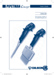
User’s Guide ENGLISH Other languages available on our website: www.gilson.com. 1 2 3 4 5 6 Introduction 3 3 Getting Started 4 Battery charging Setting-up Initializing Standby Screen 4 4 5 5 Description 5 Pipette Keypad Screen (LCD) Tip-ejector Extension 5 6 6 7 Operation 7 Switching On Thumbwheel Start Button Speed Buttons Direction Button Mode Buttons Reset Button and Connectors Tip-Ejector Button 7 7 8 8 8 8 8 8 Pipetting Modes 9 Overview Selecting Aborting the Active Mode Mode Description AUTO AUTO + MIX MANUAL REPETITIVE REVERSE Programming Modes DILUTE DILUTE AND MIX MULTIPLE ASPIRATES DISTRIBUTION WITH TIMER 9 9 9 10 10 11 12 13 14 15 15 15 15 15 Gilson Diamond® Tips 15 8 Pipetting Techniques 16 Guidelines for Good Pipetting Aspirate and Dispense GLP Features 10 System Menu 19 Configuration Beeper Screen contrast Volume limit 23 Maintenance Warnings23 Maintenance Operations23 Maintenance Operations for Single channel24 Tip-holder and Tip-ejector24 Changing the Tip-ejector24 Changing the Tip-holder24 Changing the O-ring (or seal for C10)24 Servicing the Piston25 Removing the Piston25 Maintenance Operations for Multichannel26 Removing and reassembling the Head26 Removing the Plastic Cover...26 Servicing the Ejector-cover...27 Reassembling the Piston Assemblies...27 How to Lubricate the Piston (except for C10)28 12 Cleaning and Decontamination 28 Cleaning29 External29 Internal29 Decontamination29 Autoclaving29 Chemical Decontamination 30 13 Leak Test C10 to C300 Single and Multichannel C1200 to C10ml 14 Troubleshooting 30 30 31 31 15 Accessories & Replacement Parts 32 Accessories Replacement Parts for Concept Single channel Replacement Parts for Concept Multichannel 18 18 18 18 (continued) 11 User Maintenance 16 17 General Cycle counters Alarms System Menu Calibration20 Standard Readjustment20 Quick Adjustment21 Factory Settings21 Maintenance21 Disassembly21 Service Info22 Service Settings22 Maintenance Alarm22 Pipette Info22 Personalization22 Parts Check List and Accessories 3 Accessories 7 9 10 19 19 19 19 -- 32 32 34 16 SAFETY PRECAUTIONS... 34 17 Specifications 36 18 gilson max. permissible errors 37 EC Declaration of conformity 38 notes 39 ENGLISH 1Introduction Thank you for choosing Gilson Pipetman® Concept - the latest and most user-friendly of motorized pipettes. It is another quality product from Gilson, which is fully ISO8655 compliant, CE labeled (conforms to the EC directives on in vitro diagnostic medical devices, electromagnetic compatibility and safety). To ensure the best performance from your Gilson pipette you should always use Gilson Diamond® Tips (in accordance with ISO8655) to complete your pipetting system, because Diamond Tips were used to establish the specifications cited in Chapter 17. Please refer to Chapter 16 for Safety precautions and limitations of use. 2 Parts Check List and Accessories The following items are supplied in the box: - Pipetman Concept pipette - Battery block - Sample Diamond Tips (Tipack rack or for C5000 and C10ml a bag of tips) - Guarantee and quality certificate - User’s Guide & Quick Guide - Safety bag - Tip-holder reassembly tool (Multichannel models only) - Tube of lubricant - Identification tags - Tip-ejector extension (C10 model only) Accessories The following item may be supplied either in the box or separately by your Gilson distributor: • AC adaptor (four region types are available: Europe, UK, USA/Japan, Australia). The following items are not supplied in the box: • Rapid charging and storage stand (AC adaptor not included) • PC Connection kit (includes PC cable plus programming and maintenance software) • Additional battery block Please contact your Gilson Distributor for these accessories. Order with the reference numbers given in Chapter 15. -- 3 Getting Started 1) Slide the battery block into the pipette (see fig. 1). Figure 1 2) Your Gilson distributor supplies an AC adaptor that is suitable for your country – either in the pipette box or separately. You must only use an original Gilson AC adaptor specific to this product. 3) Connect the AC adaptor to a suitable AC power supply and plug the adaptor into the pipette (see figure 2). If you have a charging stand, then you must first place the pipette on the stand and plug the adaptor into the stand. It takes two to three hours to fully charge the battery or one hour for 80% charge. We strongly recommend you fully charge the battery before using the pipette. Contacts for charging the battery from the stand Figure 2 Power Supply Battery Charging Volume range When charging the pipette you see the following screen: 20 - 300 µL Pipetman Concept Charging... Get a second battery block – that way one can be charged while the pipette is in use (you can plug the battery block into the charging stand). V2.10 Version number of the firmware Setting-up 1) Set the position of the adjustable hook to the position of maximum comfort for you size of hand (see figure 3). Loosen the retaining screw (do not undo completely), slide the hook into the most comfortable position, and then retighten the screw. 2) Fit Gilson Diamond Tips appropriate for the model of Pipetman Concept that you are using (see Chapter 7). You must always fit a tip before using any pipette. 3) Rotate the tip-adjustment force regulator until you reach the optimum force for you and the type of tip being used (see figure 3). 4) Optionally, you may personalize the name of your pipette (see Chapter 10). -- ENGLISH Initializing Press any button to activate the pipette. You then see the start-up screen: 20 - 300 µL Pipetman Concept Select your mode (see Chapter 6) and enjoy using your Pipetman Concept. Initializing... V2.10 To get used to the pipette, we recommend you select the AUTO mode. Standby Screen Pipetman Concept goes to stand-by after 3 minutes of inactivity. Press any button to reactivate the pipette. If you do not press one of the buttons within 3 minutes of the end of the current cycle, you will see the standby screen: 20 - 300 µL Pipetman Concept On stand by... V2.10 When you next press a button, the software reinitializes the piston. 4 Description 1 Pipette (figure 3) 1 Adjustable tip-ejector button, can be positioned for left or right-handed operation. 2 Ergonomic, adjustable hook, to make the pipette more comfortable to use, and to reduce fatigue. 3 4 Identity-tag window (see GLP features). 5 Tip-ejector stroke adjustment-wheel – Force Regulator. 6 Tip-ejector: removable to access piston assembly and tip-holder. 7 Optimized tip-holders to reduce tip fitting and ejection forces – removable for cleaning and servicing. 2 3 4 5 Connecting nut – links handle to the lower part. 6 7 Figure 3 -- Keypad (figure 4) The following buttons are used to control the pipette. 2 3 1 Thumbwheel to set the volume and other system parameters: setting by rolling, and validating by clicking, 2 Reset button, to initialize the pipette (see chapter 5), 3 Contacts for charging the battery from the stand (see chapter 15), 5 4 Two buttons (+) and (-) to adjust the speed, 6 5 Two mode buttons, one for right handed and one for left handed, to select the requested mode, 7 6 A button to inverse direction of piston motion (Manual mode), 7 Start button, to aspirate and dispense, 8 A button for tip ejection. 1 4 8 Figure 4 Screen (LCD) Typically, the LCD screen is used to display: - The available modes and the parameters required for a specific mode. Battery State Volume Mode and Units Piston Position !54/ - Information relating to the current manipulation in real time. - 2 3PEED#OUNT - Battery state (4 levels) - Piston direction and motion in real time (see Chapter 6). - Configuration and maintenance information (see Chapter 10). - Cycle counter (see Chapter 9). - Warning messages, which appear in the place of volume (refer to Chapter 14 for the full list). -- Speed Piston Direction Cycle Counter ENGLISH Tip-ejector Extension (only with C10 model) Figure 5 In order to eject D10 tips, tip-ejector extensions are supplied with C10 pipettes (figure 5). The tip ejector extension, which is made of PVDF (polyvinylidene difluoride), is autoclavable. Do the following to fit a tip extension. 1) Hold the pipette with the LCD uppermost and hold the extension with the slot uppermost, a) b) 2) Slide the extension over the tip-holder, 3) Push the extension firmly onto the end of the tipejector until it clicks into place (see opposite). 4) To remove a tip-ejector extension (see opposite): a) Hold the pipette in one hand and grip the extension with the other. b) Gently twist the extension (either direction) and pull it away from the pipette. 5 Operation Switching On (figure 6) Press any button to activate the pipette. After pressing a button, if nothing shows on the screen, check that the battery is charged (see Chapter 3). Speed Buttons Thumbwheel Thumbwheel There are two ways of using the thumbwheel: by rotating in either direction or by pressing inward sharply (clicking). For example, to set the volume: 1) Click the thumbwheel to unlock the volume. 2) Rotate the thumbwheel to set the volume. Mode Button Direction Button Start Button Mode Button Figure 6 3) Click the thumbwheel to lock the volume. -- The thumbwheel is also used to select parameters and to choose from the System menu. However, it always operates in the same manner; click then turn to select and click again to confirm your choice. These options are explained in the following text at the appropriate point. When setting the volume, use a sharp motion on the thumbwheel to move rapidly through the volume range or use a slow and deliberate motion to fine tune the volume. Start Button This button is the equivalent of the plunger on a manual pipette. However, very little force is needed to operate it. A simple click is all that is needed to aspirate and dispense or to purge the pipette. Speed Buttons These buttons are used to change the speed (which may be set from 1 to 5) of a pipetting cycle: + to increase the speed – to decrease the speed. The speed can be changed before or during a pipetting cycle. Direction Button Press this button to change the direction in which the piston is moving. The arrow on the screen will change accordingly. This button is only active in the MANUAL mode (see Chapter 6). Mode Buttons There are two buttons located at either side of the pipette: one each for left- or right-handed operators. Press either of these buttons to display the mode menu on the screen (see Chapter 6). Pressing both at the same time will switch the pipette to System menu (see Chapter 10). Reset Button and Connectors (figure 7) The reset button is recessed at the back of the pipette between the power supply and the PC connector. Insert a small plastic probe or a tip and press to reinitialize the pipette. PC Connector (Serial Port Interface) Reset Button Power Supply Figure 7 Tip-Ejector Button (figure 8) Tip-ejector Button This is a mechanical button that can be set for left- or righthanded users. Figure 8 -- ENGLISH 6 Pipetting Modes Overview Pipetman Concept has five pre-programmed modes. The “AUTO” mode is the recommended for the new user to become familiar with the operation of Pipetman Concept. Selecting Press either of the “Mode” buttons. The “Mode” menu shows on the LCD screen. The active mode is indicated. To select another mode, scroll the different modes by turning the thumbwheel, then press the thumbwheel to confirm. In each of the modes listed below the parameters last used are kept in memory until you change them. After a few seconds the display returns to the last mode used, if no new mode is selected. AUTO AUTO + MIX MANUAL REPETITIVE REVERSE The REVERSE mode can be replaced by another programmed mode that can be uploaded by the user with a PC Connection Kit (optional). The kit, which includes a PC cable, programming and configuration software, can be obtained from your usual Gilson representative (the reference number is F30755). Reminder: Pressing both mode buttons at the same time switches the pipette to System menu (see Chapter 10). Aborting the Active Mode If you press one of the mode buttons during the current cycle the following is displayed: If you do not press the START button within a few seconds you are sent back to the previous screen. 7!2.).' 0ROCESSABORTED 0RESS34!24TO"LOW/UT -- Mode Description auto a) Description: This is the simplest mode. Aspirate and dispense are initiated using the START button. b) Protocol: i) Click on the thumbwheel to unlock the volume setting – the current volume will flash. ii) Set the sample volume: turn the thumbwheel until you see the selected volume displayed on the screen, then press the thumbwheel to lock the volume – you cannot dispense until this is done. iii) Set the speed (optional): press the +/- keys to increase or reduce the speed (default is 5). The speed can be changed before or during a pipetting cycle. c) Functionality: i) Immerse the tip in the liquid to be aspirated. ii) To aspirate: click (press and release) the START button and wait until the motor stops (check piston position indicator). iii) To dispense: click (press and release) the START button. Three things happen: sample dispense, automatic purge and piston reset to zero. However, if you keep the button pressed until the end of the dispense cycle (when the motor stops) the piston reset takes place after you release the START button again.This feature enables you to remove the tip from the liquid – otherwise liquid would be re-aspirated when the piston resets. AUTO AUTO + MIX MANUAL REPETITIVE REVERSE !54/ - 3PEED#OUNT 6 0URGE 34!24BUTTON /PTIONAL34/0 In this mode the user has access to a cycle counter, which is incremented after each pipetting cycle. It counts up to 999 before starting again at zero. The counter is reset to zero each time the volume is changed or by pressing twice on the thumbwheel. - 10 - ENGLISH auto + MIX a) Description: This mode operates in the same way as AUTO, but is followed by a mixing phase, which is achieved by repeatedly aspirating and dispensing. AUTO AUTO + MIX MANUAL REPETITIVE REVERSE b) Protocol: i) Set the sample volume: with “AUTO” flashing on the screen, click the thumbwheel then turn it until you see the selected volume displayed, then press the thumbwheel to lock the volume. ii) Set the mix volume: with “MIX” flashing on the screen, turn the thumbwheel until you see the selected volume displayed, then press the thumbwheel to lock the volume. Then “AUTO” is displayed again. The default is the sample volume previously selected, to accept this value for mixing simply press the thumbwheel for the second time. iii) Set the speed (optional): press the +/- keys to increase or reduce the speed (default is 5). The speed can be changed before or during a pipetting cycle. Disp Asp c) Functionality: i) Immerse the tip in the liquid to be VMIX aspirated. VAUTO ii) To aspirate: click (press and release) the START button and wait until the motor stops (check piston position indicator). 0 iii) To dispense: click (press and release) the START button. Three Purge things happen: sample dispense, automatic purge and piston reset to zero. However, if you keep the Optional STOP button pressed until the end of the START button Start Purge dispense cycle (when the motor stops) the piston reset takes place after you release the START button again. iv) To mix: press the START button again; mixing continues for as long as you keep the START button pressed. Release the START button to complete the current mixing cycle. v) Purge: click on START to purge and reset the piston. “BLOW OUT” appears on the screen until the piston has reset to zero. During the normal aspirate and dispense phase the word “AUTO” appears; the volume displayed is the sample volume. During the mixing phase the word “MIX” appears ; the volume displayed is the mix volume. In this mode the user has access to a cycle counter, which is incremented after each pipetting cycle. It counts up to 999 before starting again at zero. The counter is reset to zero each time the volume is changed. - 11 - MANUAL a) Description: This mode simulates the way in which a manual pipette is operated. The user can stop and start the aspirate and dispense phases at will. This enables you to load a gel or measure a sample volume. You can also set a volume limit before aspirating a liquid phase. b) Protocol: i) Set the volume limit (optional): click on the thumbwheel than turn it until you see the selected volume limit (Vmax) displayed on the screen, then press the thumbwheel to lock the volume – you cannot dispense until this is done. If you do not set a volume, the default volume is the nominal volume of the pipette. ii) Set the speed (optional): press the +/- keys to increase or reduce the speed (default is 5). The speed can be changed before or during a pipetting cycle. AUTO AUTO + MIX MANUAL REPETITIVE REVERSE Indicates the volume aspirated or remaining to dispense Indicates the volume limit -!.5!,, - 3PEED Indicates piston direction in real time c) Functionality: i) To aspirate: keep the START 6MAX button pressed. You can stop by releasing the START button and restart by pressing it again. You can aspirate until Vmax or the nominal volume is reached. ii) Press the DIRECTION button to change the direction in which the piston moves from up to down 0URGE (see direction arrow on the dis34!24BUTTON play). You can change direction 2ELEASE34!24 3TART0URGE at any time during an aspirate or a dispense cycle. iii) Dispense: keep the START button pressed. At any time, you can stop by releasing the START button and restart by pressing it again. When the volume reaches 0.0 µL, dispensing stops. iv) Purge: click on START to purge and reset the piston. “BLOW OUT” appears on the screen until the piston has reset to zero. The volume of liquid present in the tip is permanently displayed in real time. As a consequence, you can use the MANUAL mode to measure unknown volumes. However, take care to reset the selected volume (Vmax) to the nominal volume (e.g. 1200 µL for a C1200). - 12 - ENGLISH REPETITIVE a) Description: This mode distributes a number (N) of equal aliquots. You supply the aliquot volume (AV) and the pipette automatically calculates the number from the nominal volume (NV) of the pipette as follows: N = NV/AV (e.g. 120 µL x 10 for C1200). b) Protocol: i) Set the aliquot volume: click the thumbwheel, the default volume flashes. To change the volume turn the thumbwheel until you see the required volume displayed on the screen. ii) Then press the thumbwheel to lock the volume and calculate the number of aliquots. The number of aliquots flashes. You can change the number of aliquots using the thumbwheel or simply press the thumbwheel to accept the number displayed. iii) Set the speed (optional): press the +/- keys to increase or reduce the speed (default is 5). The speed can be changed before or during a pipetting cycle. AUTO AUTO + MIX MANUAL REPETITIVE REVERSE 2%0%4)4)6% Y - 3PEED c) Functionality: V (+ extra vol)* i) Immerse the tip in the liquid to be aspirated. ii) To aspirate*: click (press and release) the START button and wait until the motor stops (check piston position indicator). 0 iii) To dispense: click (press and release) the START Purge button “N” times to sequenSTART button Optional STOP Start Purge tially dispense the aliquots. The number of aliquots left *the needed volume plus an automatically selected excess to dispense is displayed on volume. the screen. iv) iv)“BLOW OUT” appears on the screen when no aliquots are left to dispense. Click on START to purge and reset the piston. However, if you keep the button pressed until the end of the dispense cycle (when the motor stops) the reset takes place after you release the START button again. Also, you can abort the cycle (and purge) by pressing one of the mode buttons. - 13 - REVERSE a) Description: This mode is like reverse mode pipetting using a manual pipette and recommended for viscous liquid. Please refer to the Gilson Guide to Pipetting for further information. b) Protocol: i) Set the sample volume: turn the thumbwheel until you see the selected volume displayed on the screen, then press the thumbwheel to lock the volume – you cannot dispense until this is done. ii) Set the speed (optional): press the +/- keys to increase or reduce the speed (default is 5). The speed can be changed before or during a pipetting cycle. AUTO AUTO + MIX MANUAL REPETITIVE REVERSE 2%6%23% - 3PEED#OUNT c) Functionality: i) Immerse the tip in the liquid to V (+ extra vol)* be aspirated. ii) To aspirate*: press the START button, wait until the motor resets and stops at the end of the aspiration phase. iii) To dispense: press and release 0 the START button. iv) “BLOW OUT” appears on the Purge screen: click on START to purge and reset the piston. However, START button Optional STOP Start Purge if you keep the button pressed *the needed volume plus an automatically selected until the end of the dispense excess volume. cycle (when the motor stops) the reset takes place after you release the START button again. Also, you can abort the cycle (and purge) by pressing one of the Mode buttons in every modes. The REVERSE mode may replaced by a pre-programmed mode uploaded from your computer (see below). - 14 - ENGLISH Programming Modes You may replace REVERSE with your own custom built mode, which you have programmed on a Personal Computer (PC) with the Pipetman Concept Utility Software. You have total flexibility and an almost unlimited number of combinations are possible (see program guide). To operate in the program mode, you need a PC and a kit (reference F30755) containing the necessary software and connectors. The kit is available from your usual Gilson distributor (see Chapter 15). Typically you can do the following and combine protocol tasks at will: DILUTE Aspirate volumes V1 and V2 with an air gap between the two volumes then distribute the ensemble. DILUTE AND MIX Aspirate volumes V1 and V2 with an air gap between the two volumes, mix (as above), then distribute the mixture. MULTIPLE ASPIRATES Aspirate N times a volume and then distribute the ensemble. DISTRIBUTION WITH TIMER Distribute multiple aliquots with a user defined time interval between each. 7 Gilson Diamond Tips Gilson Diamond Tips are made to the highest specifications, strict quality control is maintained throughout the manufacturing process. Diamond Tips are used to calibrate Pipetman Concept, therefore for optimum performance, you are strongly advised to use Gilson’s Diamond Tips with your Pipetman Concept. Diamond Tips have the Gilson logo engraved on their collar, ensuring that you have a genuine Gilson product. To ensure accuracy and precision, Gilson’s Quality Assurance System focuses on the following critical parameters. • Diamond Tips are made from pure polypropylene (virgin, metalfree, to avoid the possibility of contamination). They are available sterilized and with filters. - 15 - Figure 9 Gilson Logo ID Number • Gilson’s sterilized Diamond Tips are certified free of detectable RNases, DNases, DNA, RNA, and proteases. • Optimized shape (revised collar for optimum sealing, thin walls, and fine point), making them easier to mount, more flexible, with no vortexing, and improved precision. • Diamond Tips are free from defects, especially at the orifice. All surfaces are smooth and hydrophobic, thereby avoiding the excessive retention of liquids that causes poor accuracy and a lack of precision. • Mold and cavity references are marked on the collar, ensuring the traceability for quality assurance purposes, batch numbers appear on all packages (bags and boxes). • They form an air-tight seal with the tip-holder, preventing the leaks that cause poor accuracy and a lack of precision. • They may be autoclaved at 121°C for 20 minutes at 0.1 MPa. 8 Pipetting Techniques Guidelines for Good Pipetting 1) Make sure that you fit new tips. 2) Each new tip(s) should be pre-rinsed with the liquid to be pipetted. 3) When aspirating, keep the tip(s) at a constant depth below the surface of the liquid (refer to Table 1). 4) Change the tip(s) before aspirating a different liquid, sample, or reagent. 5) Change the tip(s) if a droplet remains at the end of the tip(s) from the previous pipetting operation. 6) Liquid should never enter the tip holder. To prevent this: - Never turn the pipette upside down, - Never lay the pipette on its side when there is liquid in the tip(s), - Refer to the specific mode for details of the functionality. 7) The use of the Gilson Charging Stand (see Chapter 15) is recommended to store your Pipetman Concept pipette in the vertical position. 8) When pipetting liquids with temperatures different to the ambient temperature, pre-rinse the tip(s) several times before use in order to reach an equilibrium between the temperatures of the liquid and the pipette’s air-cushion. 9) For volatile liquids you should saturate the aircushion of your pipette by aspirating and dispensing the liquid repeatedly before aspirating the sample. - 16 - ENGLISH 10)After pipetting acids or other corrosive liquids that emit vapors, clean the pipette, as described in Chapter 12. 11)The pipette can be used between + 4 °C and + 40 °C, but the specifications may vary. 12)Do not pipette liquids having temperatures above 70°C or below 4°C. Extreme temperatures can affect accuracy and precision. Aspirate and Dispense 1) Fit new Gilson Diamond Tip(s) (for the best results - see “Specifications”, Chapter 17). Push the tip-holder into the tip using a slight twisting motion to ensure a firm and airtight seal. 2) Pre-rinse the tip(s). Pre-rinsing consists of aspirating the first volume of liquid and then dispensing it back into the same vessel (or to waste). Subsequent volumes that you pipette will have levels of accuracy and precision within specifications. Some liquids (e.g. protein-containing solutions and organic solvents) can leave a film of liquid on the inside the wall of the tip; pre-rinsing the tip minimizes any errors that may be related to this phenomenon. 3) Hold the pipette vertically and immerse the tip(s) in the liquid (see Table 1). Press START to aspirate the set volume of liquid. Wait a few seconds (time depends on model, see Table 1); then withdraw the pipette-tip from the liquid. You may wipe any droplets away from the outside of the tip(s) using a medical wipe, however if you do so take care to avoid touching the tip’s orifice. Table 1 - Immersion Depth and Wait Time Model Immersion Depth Wait Time (mm) (Seconds) C10, 8x10, 12x10 C100, 8x100, 12x100 C300, 8x300, 12x300 C1200, C5000 C10ml 1 2-4 2-4 2-4 3-6 5-7 1 1 1 2-3 4-5 4-5 4) Place the end of the tip(s) against the inside wall of the recipient vessel (at an angle of 10° to 40°). Press the START button. Wait for at least a few seconds before releasing the START button to expel any residual liquid from the tip(s). While removing the pipette draw the tip along the inside surface of the vessel. 5) Eject the tip(s) by pressing firmly on the tip ejector button. - 17 - 9 GLP Features Your Pipetman Concept is fully compliant to ISO8655 standard and is CE marked (for IVD and EMC directives). Pipetman Concept enables error-free manipulations, and includes the following GLP features. General • Lockable volume. • Name of model is marked on the color-coded START button. • Volume range is displayed on the screen and on the ejector-cover (Multichannel models). • Serial number is engraved on the handle of the pipette and encoded in the firmware. • Bar code: on the box and with the certificate (can be transferred). • Personalization by nametag (for marking application or user name) and by encoding in the firmware. The name appears on the screen when the pipette goes to standby (after 3 minutes of inactivity). • System menu can be locked from a PC thanks to the Utility Software (see Chapter 10). Cycle counters • From last volume setting, counts the number of cycles in the current ‘run’ (0 to 999). Appears on the main screen. • From manufacture and since the last service (see Chapter 10). • Indicators (R1, R2, R3 … Rx) each time pipette is readjusted (see Chapters 10 & 17). • Maintenance intervals can be specified by weeks or number of cycles elapsed. These and other parameters may be locked by the using the Pipetman Concept Utility Software. Alarms • Low battery warning (flashes in the place of the volume indicator). Push any button and the message disappears – this gives a few minutes of use enabling you to finish the current manipulation and then to recharge the battery (or replace with another charged battery). • Volume out of specifications warning (for Program mode). • Service is overdue warnings (see Chapter 10). • Beeper can be set On or Off. - 18 - ENGLISH 10 System Menu Press both Mode buttons at the same time to accede to the System Menu. This menu lets you choose between 4 sub-menus: Configuration, Calibration, Maintenance and Personalization. > Configuration* Calibration Maintenance Personalization Quit Select a menu by rotating the thumbwheel, then click on the required item to enter the sub-menu; select an item from the sub-menu in the same way. * asterisk means that the system menu is locked. You can modify the parameters associated with each one, provided that the sub-menu was not locked by computer-based software (using the PC Connection Kit, see Chapter 15). Configuration This menu allows you to configure the following items. Beeper: Click on the thumbwheel to set the beeper ON or OFF (the beeper will not operate, except in the case of an error or if set in Program mode). #ONFIGURATION #ALIBRATION -AINTENANCE 0ERSONALIZATION 1UIT Screen contrast: Click on the thumbwheel, rotate the thumbwheel to select a value from 1 to 5, then click again to confirm the value. Volume limit: "EEPER/&& #ONTRAST 6OLUMELIMIT 1UIT Click on the thumbwheel, rotate the thumbwheel to select a volume (default = nominal), then click again to confirm the value. To return to the currently active screen: select Quit and click to confirm. - 19 - Calibration As part of your quality system you may have standard operating procedures for pipette calibration. In accordance with ISO 8655 Gilson recommends a gravimetric procedure for pipette calibration. Please refer to “Verification Procedure for Accuracy and Precision, reference LT802292”, which you can download from the Gilson website. This gravimetric method is used to establish the mean mass of a given volume of water (taking into account evaporation losses, where necessary). After converting the mean mass to a volume (using the Z factor), you enter the measured volumes(s) into the pipettes memory and the software readjusts the pipette accordingly. Pipetman Concept allows the user to adjust the pipette quickly with maximum accuracy and with the flexibility to use one, three or four calibration points (see below). The calibration menu allows you to #ONFIGURATION 3TDREADJUSTMENT access the following items: Standard #ALIBRATION 1UICKADJUSTMENT Readjustment, Quick Re-adjustment -AINTENANCE &ACTORYSETTINGS 0ERSONALIZATION 1UIT or Factory setting. 1UIT Following readjustment by the user, Rn (R1, R2, etc) is displayed on the active screen to indicate the number of times the pipette has been readjusted since manufacture. The value of n is increased by 1 when you use Quit to leave the screen after a modification or confirmation of the values. You select the operation that you wish to perform using the thumbwheel, and then click the thumbwheel to access the corresponding parameters. After this, select the volume that you wish to enter, click the thumbwheel, turn the thumbwheel until you see the measured volume, and click to confirm the value. Continue this process for the other volumes (if any), then select Quit and click to confirm. Standard Readjustment This menu allows you to readjust the pipette using 3 calibration points: 10 %, 50 % and 100 % of nominal volume nominal (according the recommandation of ISO8655).These three values are stored in the firmware. 3TDREADJUSTMENT 1UICKADJUSTMENT &ACTORYSETTINGS 1UIT - 20 - -EASUREDVOLUME 1UIT ENGLISH Quick Adjustment This menu allows you to adjust the pipette using 1 calibration point. Effectively, by adding a fourth point to the standard calibration values. By default the value stored in the firmware is zero in which case it is not taking into account as a fourth calibration point. -EASUREDVOLUME 1UICKADJUSTMENT &ACTORYSETTINGS 1UIT 1UICKADJUSTMENTVOLUME 4ARGET -EASURED 1UIT If the value entered for Calibration volume is the same as one of the values used for the Standard re-adjustment then the Measured volume of Quick readjustment will replace the Measured volume of Standard readjustment when calculating the correction to be used. Factory Settings This option allows you to reset the volumes to the three factory calibration values (Std. Adjustment), which are permanently stored in the pipette’s firmware. If you choose this option you will erase the fourth calibration point from the Quick Readjustment procedure. Maintenance This menu allows you to check and set parameters relating to pipette maintenance. Select a submenu by rotating the thumbwheel, then click on the required item to enter the sub-menu; select an item from the sub-menu in the same way. Routine maintenance procedures are described in the next Chapter. #ONFIGURATION #ALIBRATION -AINTENANCE 0ERSONALIZATION 1UIT Disassembly This option allows you to disassemble the lower part safely (protection of the piston and the motor). If you select “Disassembly”, the following screen appears: $ISASSEMBLY 3ERVICEINFO 3ERVICESETTINGS 0IPETTEINFO 1UIT )TISNOWSAFETO DISASSEMBLETHE ,OWERPART 1UIT To close the “Disassembly” menu, the only possibility is to choose “Quit”. If you select “Quit”, a confirmation message appears. If you select “No”, the display will return to the “Disassembly” menu. If you select “Yes”, you must first ensure that the pipette has been correctly reassembled (see Chapter 11). The software then resets the piston and the display returns to the last mode used. - 21 - Service Info This screen is read only – you cannot modify any of the items, which are: the number of cycles and the date since the pipette was serviced. $ISASSEMBLY 3ERVICEINFO 3ERVICESETTINGS 0IPETTEINFO 1UIT Last Service > Cycles: 20537 Date: 18 JAN 07 Quit Service Settings Select an item by rotating the thumbwheel, then click on the required item to select it; rotate the thumbwheel to select a value (e.g. “Weeks”) and then click on the thumbwheel to confirm. You can change four variables: “Cycles” to next service, “Weeks” to next service, “Date” of the service, and “Alarm” (see below). When it comes to setting the date, you have three fields to modify, one after the other, day - month - year (dd mm yy) in the same way as the other parameters mentioned above. The 3 letters for the months are as follows; JAN, FEB, MAR, APR, MAY, JUN, JUL, SEP, OCT, NOV, DEC. $ISASSEMBLY 3ERVICEINFO 3ERVICESETTINGS 0IPETTEINFO 1UIT Cycles: 20000 > Weeks: 36 Date: 18 JAN 07 Alarm: ON Quit Maintenance Alarm By default the maintenance alarm is set to OFF – rotating the thumbwheel alternates between On and Off confirm by pressing the thumbwheel. Warning messages will be displayed depending on the maintenance settings that you make (see Chapter 11). Pipette info This screen is read only – you cannot modify any of the items, which are: - The serial number of the pipette. - The version of the firmware. - The number of cycles since the pipette was manufactured. $ISASSEMBLY 3ERVICEINFO 3ERVICESETTINGS 0IPETTEINFO 1UIT S/N: Z10001A Firmware: V2.10 Total cycles: 41353 > Quit Personalization This menu allows you to personalize the standby screen. Select “New Id”. With the cursor aligned as shown (>A), click and turn the thumbwheel to select a character and click it to confirm. You may enter a string of up to 15 alphanumeric characters. Use the asterisk (*) to signal that you have entered the last character; use / to cancel. #ONFIGURATION #ALIBRATION -AINTENANCE 0ERSONALIZATION 1UIT - 22 - )D0)0%4-!.#ONCEPT .EW)D ! CONFIRM CANCEL 1UIT ENGLISH 11User Maintenance It is best to inspect your pipette regularly and to routinely clean and change parts if required. To help you to keep up a regular schedule and in the interests of GLP, you can configure your pipette to display an alarm before a service is due (refer to Chapter 10). Setting maintenance alarm to “On” results in the following messages. Maintenance Warnings • Date of next service: warning about 1 week before and if overdue. • If you exceed a service interval that was set relative to the number of pipetting cycles, the system flashes the following message place of the volume indicator. Cycles: 20000 > Weeks: 36 Date: 18 JAN 07 Alarm: ON Quit Push any button and the following is displayed. Select “Maintenance ?” to go to the system menu or “Remind me later” to delay by one day. • If you exceed a service interval that was set relative to a time limit, the system flashes the following message place of the volume indicator. 3%26)#%0)0%44%./7 ;4IMELIMITPASSED= -AINTENANCE 2EMINDMELATER Select “Maintenance ?” to go to the system menu or “Remind me later” to delay by one day. Maintenance Operations You may perform the following operations yourself. - Clean or autoclave the parts specified under “Cleaning and Decontamination”, Chapter 12 - Change the parts specified under “Replacement Parts”, Chapter 15 - Lubricate the piston, - Change the battery. Please contact your Gilson distributor if you require their assistance in the form of training or if you would like to enter into a service contract with them. Go to Maintenance>Disassembly and confirm to disassemble the lower part safely (see page 21). - 23 - Maintenance Operations for Single-channel models Tip-holder and Tip-ejector These parts must be changed, if they are accidentally damaged or attacked chemically. You should also remove these parts for cleaning or decontamination purposes. Changing the Tip-ejector Figure 10 1) Keep the tip-ejector button depressed, and grip the top of the tip-ejector with the other hand. 2) Gently rotate the tip-ejector counterclockwise and separate its connector from the activating rod (figure 10). 3) Pull the tip-ejector away from the handle of the pipette. 4) Clean or autoclave the tip-ejector and refit it (or a new one) by reversing the procedure. Changing the Tip-holder (lower part) After removing the tip-ejector, you may remove the lower part of the tip-holder, which is more likely to become contaminated or damaged than the upper part. Removal of the lower part is shown below; for the upper part refer to “Removing the Piston” (special precautions are necessary). 1) Gently rotate the lower part of the tip-holder counterclockwise to unscrew it from the upper part (figure 11). Figure 11 2) Separate the parts and remove the O-ring (see “Changing the O-ring”, figures 12 and 13). 3) Clean and if required autoclave the lower part of the tipholder. Figure 12 4) If required lubricate the piston (see “How to Lubricate the Piston”) and fit a new O-ring. 5) Screw the two parts together; making sure that the two parts are fully tightened by hand, using latex gloves. Figure 13 6) Refit the tip-ejector. Changing the O-ring (or seal for C10) The O-ring is contained by the two halves of the tip-holder; if worn or damaged in any way, it must be replaced. To access the O-ring, remove the tip-ejector and unscrew the lower part of the tip-holder - if the O-ring is not immediately visible on the piston, select the AUTO mode then set the volume to the nominal and press the ACTION button.You should now be able to remove the O-ring from the piston. Sometimes, the O-ring may be found in the recess at the top-end of the lower part of the tip-holder. - 24 - ENGLISH If required lubricate the piston (see “How to Lubricate the Piston”) then fit a new O-ring by sliding it onto the piston. Reassemble the pipette. Servicing the Piston You may remove the piston-assembly to clean, lubricate, or change the piston. The specifications of the pipette must be checked after changing the piston. Removing the Piston Use the stand-by procedure (Disassembly, see Chapter 10: “Maintenance”). 1) Select the “Disassembly” option in the System menu (System menu>Maintenance>Disassembly). Figure 14 2) Remove the tip-ejector and (optionally) the lower part of the tip-holder. If you remove the lower part, take care to remove the piston seal as described in “Changing the O-ring”. 3) Unscrew the connecting-nut (turn by hand, counterclockwise, figure 14). 4) Pull on the spring guide to remove the piston assembly from the handle of the pipette - separate the parts (figure 15). For C5000 and C10 ml, the connecting nut is combined with the upper part of the tip-holder (see “Spare Parts”). 5) Clean and autoclave (if required) the piston and holder, together with any other parts that may need to be treated in the same way (see “Cleaning and Decontamination”). 6) Lubricate the piston (except C10), see at the end of chapter. 7) Reassemble the piston, spring and spring guide; then carefully insert the assembly into the handle of the pipette (figure 16).The spring guide should hold the piston assembly inside the handle of the pipette. Take care to position the small- diameter end of the spring as shown (innermost), and that the flanged end of the spring guide is outermost. 8) Reassemble the upper part of the tip-holder and the connecting nut, and then refit to the handle of the pipette by rotating the connecting nut clockwise until it is finger tight (figure 17). Fit the seal and reassemble the lower part of the tip-holder. Refit the tip ejector. - 25 - Tip-holder (lower) Connecting nut Figure 15 Spring guide Tip-holder (upper) Piston Spring (tapered) Piston holder Figure 16 Figure 17 The seal for C10 is fragile and can only be used once. So, after unscrewing the lower part of the tip-holder you must fit a new seal. 9) Quit the “Disassembly” screen (Quit>Yes). Maintenance Operations for Multichannel models Removing and reassembling the Head Figure 18 Use the stand-by procedure (Disassembly, see Chapter 10: “Maintenance”). 1) Select the “Disassembly” option in the System menu (System menu>Maintenance>Disassembly). 2) Keep the tip-ejector button depressed and grip the ejector-clip. 3) Unlock the ejector-clip and separate it from the activating rod (figure 18). 4) Unscrew the connecting nut. 5) Extract the head. 6) After reassembling the head, quit the “Disassembly” screen (Quit>Yes). Removing the Plastic Cover, Piston Assemblies and Tip-holders 1) Remove the two screws, which are located at either side of the head, using a miniature screwdriver (figure 19). Figure 19 Figure 20 2) Gently pull the ejector-cover away from the head (figure 20). 3) Remove the wire clips (+ wire guides for 12 channels-models) from the piston tray-cover (figure 21). 4) Lay the pipette flat and push awards (with your thumbs) on the catches at either side of the piston-tray cover (figure 22). The cover will flip upwards to reveal piston and tip-holder assemblies. 5) Lift the tip-holder upwards, away from the lower rake, then push the tip-holder back along the axis of the piston. Figure 21 Wire clips Pistons Tip-holders (+ wire guides for 12 channel-models) - 26 - Figure 22 Rake (upper) Rake (lower) Wire guides Wire clips ENGLISH Now, pull the piston away from the upper rake and lift it and the tip holder out of the tray, taking care not to lose or damage the piston spring. 6) Gently pull the piston assembly out of the tip-holder. Servicing the Ejector-cover, Piston Assemblies and Tip-holders (all models except Multichannel x10) Tip-holder 8x300/12x300 The tip-holders and piston assemblies must be changed, if they are accidentally damaged or attacked chemically (figures 23 and 24). Figure 23 You should also remove them for cleaning or decontamination purposes, and to lubricate the pistons. 1) Examine the ejector-cover, if it is cracked or badly corroded it should be replaced with a new part. Otherwise, it should be cleaned and if necessary autoclaved. 2) Check the piston for damage or corrosion. Lubricate and replace as necessary. 3) After removing the locking clip, gently pry out each tip-holder’s internal components: locking-clip, spring, O-ring and seal-holder (figure 25) – this can be done using the reassembly tool. Replace or clean and decontaminate these components. Replace or clean and decontaminate the tip-holder. The O-ring can get trapped in tip-holder. Use a fine plastic probe to extract the O-ring. Piston Piston spring Figure 24 O-ring Seal holder Tip-holder spring Figure 25 Reassembling the Piston Assemblies, Tip-holders, and Plastic Ejector-cover A) Tip-holders 1) Use a lubricated piston to transfer a small quantity of lubricant to the O-ring. 2) With reference to the figure 26, place the components on the reassembly tool in the following order: locking-clip, tip-holder spring, seal-holder, O-ring – take care that the spring is the correct way up and the flat surface of seals, rings and washers faces the spring. 3) Insert the components into the tip-holder with the aid of the reassembly tool. 4) Push on the locking-clip until it snaps into place. - 27 - Locking-clip x300 Seal (O-ring) Seal holder Spring Locking-clip Figure 26 B) Piston Assemblies 1) Lubricate the piston, as described in the section below. 2) Gently, slip a lubricated piston into the tip-holder, with a slight twisting motion. Avoid using too much force as this could dislodge the O-ring. C) Closing-up 1) Refit each tip-holder/piston assembly so that the top of the piston and the tip-holder snap into the upper and lower rakes, respectively. To facilitate fitting a piston assembly to the upper rake, you should incline the piston assembly and compress the pistonspring against the upper rake, before pushing the assembly into place. 2) Close the piston tray-cover, after checking that all assemblies are correctly installed. 3) Refit the wire-clips (+ wire guides for 12 channel-models). 4) Slide the ejector-cover back over the piston-tray and reattach using the two screws. How to Lubricate the Piston (all models, except C10 and Multichannel x10) Use only Gilson lubricant (ref: F3070902, as supplied). Squeeze a small quantity from the tube onto a clean, nonabrasive cloth. Use the cloth to transfer the lubricant to the piston. Ensure that the piston is evenly lubricated, and that you wipe away any excess - remember only a fine film of lubricant is required (over the entire piston). 12 Cleaning and Decontamination Pipetman Concept is designed so that the parts normally in contact with liquid contaminants can easily be cleaned and decontaminated. As part of your quality system, you may have procedures for pipette decontamination. We recommend that you refer to “Decontamination Procedures for Gilson Pipettes” (reference LT802288), which you can download from Gilson’s website. Liquid must not enter the handle of the pipette. If you use chemical solutions for decontamination or detergents for cleaning, other than specified below, you should check with your supplier that the solution or detergent used does not attack any of the following materials: stainless steel, POM (Polyoxymethylene), PVDF (Polyvinylidene fluoride), PC (Polycarbonate) and PBT (Polybutylene Terephthalate). - 28 - ENGLISH Cleaning The pipette must be cleaned, as described below, before it is decontaminated. You may use a simple soap solution for cleaning Pipetman Concept or any of the solutions mentioned in “Decontamination Procedures for Gilson Pipettes” (reference LT802288). External 1) Remove the tip-ejector (see Chapter 11). 2) Wipe the tip-ejector with a soft-cloth or lint- free tissue impregnated with soap solution. 3) Wipe the entire pipette with a soft-cloth or lint-free tissue impregnated with soap solution, to remove all dirty marks. If the pipette is very dirty, a brush with soft plastic bristles may be used. 4) Wipe the entire pipette and the tip-ejector with a soft cloth or lint-free tissue impregnated with distilled water. Internal The following components only can be immersed in a cleaning solution: tip-ejector, tip-holder (both parts), connecting nut, piston (including holder), return spring, and spring guide. 1) Disassemble the pipette as described in Chapter 11. 2) Set aside the upper part in a dry and secure location. 3) Clean the individual components of the lower part of the pipette using an ultrasonic bath (20 minutes at 50°C) or with a soft-cloth and brushes. Small round brushes with soft plastic bristles may be used to clean the interior of the tip-holder. 4) Rinse the individual components with distilled water. 5) Leave the parts to dry by evaporation or wipe them with a clean soft-cloth or lint-free tissue. 6) Lubricate the piston and reassemble the pipette according to the instructions given earlier in the previous chapter. Decontamination Autoclaving The handle of the pipette is not autoclavable. Only the following parts may be autoclaved individually: tip-ejector, tip-holder (both parts), connecting nut, piston (including holder), return spring, spring guide, O-ring (warning: can be damaged when autoclaved), and airtightness kit (Multichannel models). 1) Clean the parts to be autoclaved, especially the tip-holder. 2) Put the parts in an autoclaving sack. 3) Autoclave at 0.1 MPa at 121°C for 20 minutes. 4) Check that the parts are dry before reassembling the pipette. 5) Set the pipette aside to stabilize at room temperature. - 29 - The specifications of the pipette must be checked after autoclaving. Chemical Decontamination You may choose to decontaminate your pipette chemically, in accordance with your own procedures. Whatever decontaminant you use, check that it is compatible with the plastics used in the construction of the pipette (see previous page). • Parts that may not be immersed 1) Wipe the handle of the pipette with a soft-cloth or lint-free tissue impregnated with the chosen decontaminant. 2) Wipe the handle of the pipette with a soft-cloth or lint-free tissue impregnated with distilled water. • Parts that may be immersed The following components only can be immersed in a decontaminant solution: tip-ejector, tipholder (both parts), connecting nut, piston (including holder), return spring, and spring guide. 1) Disassemble the pipette as described in “Maintenance”. 2) Immerse the components in the decontaminant solution or wipe them according the instructions given by the manufacturer or supplier of the decontaminant. 3) Rinse the individual components with distilled or sterile water. 4) Leave the parts to dry by evaporation or wipe them with a clean lint-free tissue or soft-cloth. 5) Lubricate the piston and reassemble the pipette according to the instructions given in this chapter. 13 Leak Test This test may be performed at any time to check that the pipette does not leak, especially after performing a maintenance or decontamination procedure. If a pipette fails this test you should replace the O-ring and seal and repeat this test, after making sure that the pipette is correctly reassembled. C10 to C300 Single and Multichannel - fit a Gilson Diamond Tip, - set the pipette to the maximum volume given in the specifications, and pre-rinse, - aspirate the set volume from a beaker of distilled water, - maintain the pipette in the vertical position and wait for 20 seconds, - if a water droplet appears at the end of the tip there is a leak, - 30 - ENGLISH - if you see no droplet, re-immerse the tip below the surface of water, - the water level inside the tip should remain constant; if the level goes down there is a leak. C1200 to C10ml - fit a Gilson Diamond tip, - set the pipette to the maximum volume given in the specifications, - aspirate the set volume from a beaker of distilled water, - maintain the pipette in the vertical position and wait for 20 seconds, - if a water droplet appears at the end of the tip, there is a leak. 14 Troubleshooting In case of malfunction, first press the reset button located in the back of the pipette between the power supply and the PC connector. Insert a small plastic probe (like a tip) in the hole and press. If the problem persists, you may consult the following table wich identifies potential problems and their solutions. Before returning any pipette to your local Gilson Service Center, ensure that it is completely free of chemical, biological, or radioactive contamination. Please use the included safety bag. Symptom Possible Cause Refer to page Pipette is leaking sample Worn O-ring 23-24, 26 Pipette won’t aspirate Worn O-ring 23-24, 26 Unscrewed lower part of tip holder 23 Damaged or corroded piston 24-26 Damaged tip holder 23, 25-27 Improper repair or assembly 22-27 Connecting nut is loose 25 Noisy operation Piston needs lubricating Pipette is inaccurate Improper repair or assembly 22-27 Unscrewed lower part of tip-holder 23 Pipette is out of adjustment 18-20 Connecting nut is loose 25 Pipette is not precise Unscrewed lower part of tip-holder 23 Incorrect operator technique 15-16 Worn O-ring 23-24, 26 Connecting nut is loose 25 Damaged or corroded piston 24-26 Damaged tip-holder 23, 25-27 Tips fall off or don’t fit Low quality tips Damaged tip-holder Damaged tip-ejector No LCD display Pipette is not switched on Battery needs recharging - 31 - 27 14-15 23, 25-27 24-26 7 4 15Accessories & Replacement Parts Accessories Item Reference Rapid Charging Stand F30750 PC Connection Kit (including Pipetman Concept Utility Software) F30755 Pipetman Concept Utility Software F3075502 Name Tag F3071107 AC-adapter Europe F30701 AC-adapter USA/Japan F30702 AC-adapter UK F30703 AC-adapter Australia F30704 Replacement Parts for Pipetman Concept Single channel Item C10 C100 C300 C1200 C5000 C10ml Battery block F3071165 F3071165 F3071165 F3071165 F3071165 F3071165 Adjustable hook F3071110 F3071110 F3071110 F3071110 F3071110 F3071110 Personalization window F3071103 F3071103 F3071103 F3071103 F3071103 F3071103 Tip ejector assembly F2070159 F2070459 F2070559 F2070659 F2070759 F2070859 Piston assembly F3071252 F3071352 F3071452 F3071552 F3071652 F3071752 Return spring F2070113 F2070113 F2070113 F2070113 - - Spring guide F307115451 F307115451 F307115451 F307115451 - - Tip holder, upper part - - O-ring, x 5 (or seal for C10) F161902 F2070401 F307145351 F2070601 F2070701 F2070801 Tip holder, lower part F2070218 F2070418 F307145301 F2070618 F2070719 F2070819 Connecting nut F2072111 F2072111 F2072111 F2072111 - - F2070903 - - - - - Lubricant tube 3.5 g - F3070902 F3070902 F3070902 F3070902 F3070902 Bag of 10 filters - - - - F161280 F161280 Bag of 100 filters - - - - F161240 F161240 Tip ejector extension for C10 F2070117 F2070417 F307145302 F2070617 - 32 - ENGLISH The airtightness kit include the following items: ☞ 1)Locking-clip, Spring, Seal holder, Seal (O-ring). Figure 28 2) The tip-holder assembly includes the above items fitted into the tip-holder. - 33 - Replacement Parts for Pipetman Concept Multichannel Item 8x10 8x100 8x300 12x10 12x100 12x300 Battery block F3071165 F3071165 F3071165 F3071165 F3071165 F3071165 Adjustable hook F3071110 F3071110 F3071110 F3071110 F3071110 F3071110 Personal. window F3071103 F3071103 F3071103 F3071103 F3071103 F3071103 F2073361 Screws and wire clips kit F2073261 F2073261 F2073261 Tip holder assembly G-F.I.T. system F3073255 F3073355 F307326306 F3073255 Ejector cover Piston assembly Air tightness kit F2073361 F2073361 F3073355 F307326306 F307325051 F307335051 F2073259 F307425051 F307435051 F2073359 F3073254 F3073354 F3073454 F3073254 F3073354 F3073454 - F3073360 F2073265 - F3073360 F2073265 Reassembly tool F3073201 F3073301 F2073201 F3073201 F3073301 F2073201 Lubricant tube 3.5 g - F3070902 F3070902 F3070902 F3070902 F3070902 16safety precautions and limitations of use For safety reasons, it is important to observe the following instructions: 1- Battery and electrical specifications - We strongly recommend you fully charge the battery before using the pipette. - Your Gilson distributor supplies an AC adaptor that is suitable for your country - either in the pipette box or separately. You must only use an original Gilson AC adaptor specific to this product. Charge the battery in the pipette, using the AC-adapter or the charging stand, or in the charging stand (slot for additional battery). - Use AC-adaptor and charging stand indoors. - When handling the battery, do not allow the battery to come into contact with any metallic surfaces. Do not short circuit. - Dispose of used batteries in accordance with legal regulations. Batteries may not be disposed of with household waste and may explode if disposed in fire ! • • Li-ion battery pack; 1 Ah / 3.6 V Charging time: approx. 2 hours for a fully discharged battery (80% in one hour). Symbol means: Caution, risk of danger. AC adaptor (may be not included; see above) Input voltage, country-specific: 100-240 V, 50/60 Hz (0.5A max.) Output voltage: +5 V DC; 3.5A (17.5W max.) - 34 - ENGLISH 2- Do not use Pipetman Concept in a potentially explosive environment or with potentially explosive chemicals. 3- When pipetting infectious, radioactive, toxic and other hazardous solutions, please observe all the safety precautions (e.g. wear protective clothing, goggles and gloves) and regulations appropriate for your country. 4- Do not allow the liquid to enter the body of the pipette. 5- Storage conditions Temperature: -20°C to 50°C Humidity max: 80% 6- Temperature of use Between 4°C and 40°C (specifications may vary). 7- Use only original Gilson’s Diamond tips, accessories and spare parts. If the equipment is used in a manner not specified by Gilson in the user’s guide, the protection provided in the equipment may be impaired. 8- Equipment disposal This equipment must not be disposed of with unsorted municipal waste. Instead, it is your responsibility to correctly dispose of your waste equipment by handing it over to an authorised facility for separate collection and recycling. It is also your responsibility to decontaminate the equipment in case of biological, chemical, and/or radiological contamination so as to protect from health hazards the persons involved in the disposal and recycling of equipment. For more information about where you can drop off your waste equipment for recycling, please contact your local dealer from whom you originally purchased the product or your local council. By doing so, you will help conserve natural resources and you will ensure that your waste equipment is recycled in a manner that protects human health and the environment. Thank you! - 35 - 17 Specifications Pipetman Concept is a high quality pipette that offers excellent accuracy and precision. The figures given in the “Gilson Maximum Permissible Errors” table were obtained using mode AUTO (speed 5). These figures are only guaranteed using Genuine Gilson Diamond Tips. Each pipette is inspected and validated by qualified technicians according to the Gilson Quality System. Gilson declares that its manufactured pipettes comply with the requirements of the ISO 8655 Standard, by type testing. The adjustment is carried out under strictly defined and monitored conditions (ISO 8655-6): • Basis of adjustment, Ex. • Reference temperature, 20 °C • Relative humidity, 50 % • Barometric pressure, 101 kPa • Use of distilled water grade 3 (ISO 3696) • Ten measurements for each test volume, which are Nominal Volume, 50 % of Nominal Volume, and 10% of Nominal Volume. - 36 - ENGLISH 18 GILSON Maximum Permissible Errors Tested mode: AUTO. Speed: 5. Model/Color coding (Reference) Range Diamond Tips* Volume (µL) The data conform to ISO 8655-2 Standard. Gilson Systematic Random error (µL) error (µL) ISO 8655 Systematic Random error (µL) error (µL) C10/Red D10 (F31012) DL10 0.5 - 10 µL 0.5 1 5 10 ± 0.040 ± 0.025 ± 0.060 ± 0.080 0.013 0.012 0.020 0.025 ± 0.120 ± 0.120 ± 0.120 ± 0.120 0.080 0.080 0.080 0.080 C100/Peach D200 (F31013) 5 - 100 µL 5 10 50 100 ± 0.35 ± 0.30 ± 0.38 ± 0.40 0.10 0.10 0.12 0.15 ± 0.80 ± 0.80 ± 0.80 ± 0.80 0.30 0.30 0.30 0.30 C300/Green D300 (F31014) 20 - 300µL 20 30 150 300 ± 0.80 ± 0.70 ± 0.90 ± 1.05 0.16 0.20 0.23 0.30 ± 4.00 ± 4.00 ± 4.00 ± 4.00 1.50 1.50 1.50 1.50 C1200/Blue D1200 (F31015) 100 - 1200µL 100 120 600 1200 ± 2.5 ± 2.4 ± 3.6 ± 6.0 0.4 0.4 0.8 1.2 ± 16.0 ± 16.0 ± 16.0 ± 16.0 6.0 6.0 6.0 6.0 C5000/Purple D5000 (F31016) 500 - 5000µL 500 2500 5000 ± 10 ± 15 ± 25 2 4 7 ± 40 ± 40 ± 40 15 15 15 C10ml/Light blue D10ml (F31017) 1 - 10mL 1 mL 5 mL 10 mL ± 25 ± 30 ± 50 4 8 12 ± 60 ± 60 ± 60 30 30 30 8x10 - 12x10/Red DL10 (F31032) - (F31042) 0.5 - 10µL 1 5 10 ± 0.04 ± 0.08 ± 0.10 0.02 0.04 0.06 ± 0.24 ± 0.24 ± 0.24 0.16 0.16 0.16 8x100 - 12x100/Peach D200 (F31033) - (F31043) 5 - 100µL 10 50 100 ± 0.25 ± 0.50 ± 0.80 0.14 0.20 0.25 ± 1.60 ± 1.60 ± 1.60 0.60 0.60 0.60 8x300 - 12x300/Green D300 (F31034) - (F31044) 20 - 300µL 30 150 300 ± 1.0 ± 1.5 ± 2.4 0.18 0.38 0.60 ± 8.0 ± 8.0 ± 8.0 3.0 3.0 3.0 * Recommended tip for establishing maximum permissible errors (ISO 8655 requirement). A large range of suitable Gilson Diamond tip is available. Please contact your local Gilson distributor for further information. - 37 - Villiers-le-Bel, September 14th, 2005 Atika El Sayed General Manager Hervé Ledorze Quality Manager - 38 - ENGLISH Notes - 39 - LT801489/C - ©2007 Gilson SAS All rights reserved English June 2007 Printed in France World Headquarters Gilson, Inc. 3000 Parmenter Street, P. O. Box 620027, Middleton, WI 53562-0027, USA Telephone: (1) 800-445-7661 or (1) 608-836-1551 Fax: (1) 608-831-4451 Gilson SAS 19 avenue des Entrepreneurs, B. P. 145, 95400 Villiers-le-Bel, France Telephone: (33) 1-34-29-50-00 Fax: (33) 1-34-29-50-20