1
Dual Axis Laser with Gradient
LDAL310S
User Guide
LDAL310S
A Dual Gradient Laser of extremely rugged design – for civil and
construction engineering applications
High-precision Rotary Gradient Laser, 5° horizontal self-levelling range, accuracy
0,5 mm / 10 m. Gradient can be set digitally in both X and Y axes. Electronic vials and
positioning motors controlled by temperature-stable sensors for automatic horizontal
alignment. Highest reliability is guaranteed through the ant-drift system (ADS): The electronics
permanently monitor the measuring process and switch the laser off in the case of any
outside interference or disturbance. The laser beam can be switched off in sections. Laser
modes: rotary and hand receiver mode. High maximum speed of 1100 rpm, the telescopic
sight supplied with the device makes alignment easy, large illuminated LCD.
General safety instructions
Caution: Do not look directly into the beam. Lasers must be kept out of reach of children.
Never intentionally aim the device at people. This is a quality laser measuring device
and is 100% factory adjusted within the stated
LASER Radiation
DO NOT Stare INTO THE BEAM! tolerance. For reasons of product liability, we must
CLASS 2 LASER
< 1 mW · 635 nm
also draw your attention to the following: Regularly
EN 60825-1:2007-10
check the calibration before use, after transport and
after extended periods of storage. We also wish to point out that absolute calibration is
only possible in a specialist workshop. Calibration by yourself is only approximate and the
accuracy of the calibration will depend on the care with which you proceed.
Note:
This product is a precision instrument that must be handled and treated with care. Avoid
shocks and impact. Always keep and carry in the case! Switch laser off. For cleaning, use
a soft cloth and glass cleaner.
Warranty
The warranty period is two years from the date of purchase. The warranty covers all material
and manufacturing defects occurring during this time. The following are excluded from
warranty: Damage due to improper use (e.g. connection to an unsuitable power source, falling
onto a hard surface, etc); improper storage; normal wear and tear; minor defects not impairing
operation. Any tampering by unauthorized persons will render the warranty void. In the event
that you need to claim warranty, please return the complete device together with proof of
purchase to the place of purchase or to the Service address on the back page.
2
Quick Reference Guide
(34)
Switching the
unit on for the
first time
Switch the unit on using the ON/OFF button (34). The laser
rotates at a speed of 600 rpm and the automatic sensors
are active.
Remote control
The remote control can be used to control all functions
except gradient entry. Standby mode is activated by
pressing the standby button (37). All settings are retained.
Rotating speed
Press the rotation button (35) to switch speeds (0; 300;
600; 1100 rpm).
Digital slope
function
Press the X button (27): The first digit starts to flash. Press
the plus/minus buttons (28) to enter a positive, zero or
negative value. Press the X button to select the values of
subsequent digits. Numerical values can be set using the
plus/minus buttons (28). The Y button functions in the same
way as the X button.
Important: You must confirm your entries by pressing
Enter (29); the rotary laser will then set the required value.
Value entry is disabled during levelling ("SLOPE" flashes on
the LCD (19)). Once levelling is complete and value entry
has been reactivated, "SLOPE" will stop flashing and will be
displayed permanently on the LCD.
Manual slope
function
This function is used to deactivate automatic levelling.
Large deviations from the horizontal and vertical planes
can now be set using an optional external tilt plate. To do
this, press the auto/man button (32). „MAN“ will appear on
the LCD (24). Note: The DualAxis-Laser is not capable of
motorized slope adjustment in auto/man mode. Important:
As the automatic sensors are not active, horizontal levelling
is not possible.
(37)
(35)
(27)
(31)
(28)
(28)
(29)
(32)
3
LDAL310S
(33)
(30)
(28)
Tilt
function
Once the rotary laser has been levelled and the automatic
sensors are running, press the tilt button (33). It takes
approximately 30 seconds to activate tilt. If you move the
unit during this time, it will switch itself off. The laser and
"TILT" (22) flash. Press the tilt button again to reactivate
the automatic sensors; tilt will be reactivated within
approximately 30 seconds. Once the tilt function has been
activated, it can be deactivated by pressing the tilt button
again.
Important: The tilt function is not active in standby mode.
Laser segment
mode
Press the segment button (30). The top segment (21)
flashes on the LCD. Use the plus/minus buttons (28) to
activate/deactivate the segment. Press the segment button
again to move to the next segment. Press Enter (29) to
confirm the setting and transfer it to the laser.
Illuminated
display
Press and hold down Enter (29) on the rotary laser for
at least 2 seconds to activate/deactivate the illuminated
display.
Power management
The unit can run on rechargeable batteries, standard
alkaline batteries and a mains power supply. Running the
unit on a mains power supply will charge its rechargeable
batteries.
Calibration
Press and hold down the auto/man button (32). With the
auto/man button held down, press the ON/OFF button (34)
until CAL (36) appears on the display. Open the calibration
compartment on the remote control unit and select the X
axis by pressing the X/Y button (38). You can now set the
selected axis using the plus/minus buttons (39). Proceed
in the same way to set the Y axis. Save the new setting by
pressing Enter (40).
(28)
(29)
(29)
(32)
(34)
(38)
(39)
(39)
(40)
4
LDAL310S
Operation of the DualAxis-Laser
Charging the batteries
• The battery symbol (26) will flash constantly on
the LCD (I) to indicate that the batteries need
changing or recharging.
• Open the battery compartment (K), insert the
batteries and connect the plugs to the sockets.
The plugs fit in the sockets in one position
only (see pictures on right). Reclose the battery
compartment.
• Connect the battery charger/mains unit to a mains
source and plug into the socket (F). Please only
use the charger/mains unit supplied with the
device. If a different one is used, the warranty will
become void.
• The device can also be operated with standard
alkaline batteries (4 x type D). Insert the batteries as shown by the installation symbols.
Ensure the polarity is correct.
Inserting batteries into the SensoLite laser receiver
• Open the battery compartment (8) and insert the battery according to the installation
symbol, making sure that you do not reverse the polarity. Replace the cover.
• In order to save battery power the receiver will switch itself off automatically after
approximately 5 minutes of inactivity.
Note:
Do not expose batteries to excessive heat such as sunshine, fire, etc. Dry batteries must not
be recharged. Used batteries must not be disposed of as household waste.
5
Deutsch
1
LDAL310S
A
B
K
C
D
E
E
°
90
Y-axis
F
G
H
I
J
X-axis
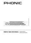
Alignment
A Scope
G Battery charge indicator
B View point
H 5/8" tripod thread (base)
C Scope mounting plate
I LC-Display
D Prism head
J Control panel
E Receiver diode for remote control
K Battery compartment
F Charger socket (DC 9V)
Deutsch
6 1
LDAL310S
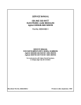
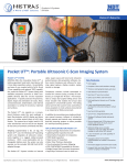
Included accessory:
SensoLite 310
11
Protection class IP 66
2
3
12
13
4
14
1
15
10
16
9
8
6
17
5
7
18
Close-up of detector
1 All-round marking groove
12 Detector above laser level
2 Laser beam sensors
13 Precisely on laser level
3 SpotLite Marking LED
14 Detector below laser level
4 Levelling vial
15 Volume indicator
5 Clamping screw for levelling staffs
16 Low battery indicator
6 Universal mount
17 Detector mode /
7 Binding screw (rear side)
Switch: Precision range
8 Battery compartment (rear side)
Free-hand range
9 Control panel
18 Volume adjustment
10 LC-Displays (front and rear side)
11 Display measuring range selection
7
LDAL310S
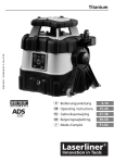
Commander
DAL 50
LC-Display and control panel
DualAxis-Laser
34 33
19 41 36 35
20
32
CAL
21
31
22
MAN
23
24
37
25
Tilt
LEV
26 27
30
28 29
19 Digital Slope function indicator
20 Digital slope adjustment X- and Y-axis
indicator
28
35
30
28
38
29
40
39
32 auto/man-function
33 Tilt-function
22 Tilt function indicator
34 ON/OFF button DualAxis-Laser
23 Rotation speed indicator
35 Select rotation speed 0 / 300 / 600 /
1100 rpm
25 Sensor-Automatic indicator
33
31 Activate the slope adjustment of the
Y-axis / select data zone
21 Indicator of the laserbeam area
24 auto/man function indicator
32
36 Calibration mode indicator
26 Low battery indicator
37 Activate standby mode on DualAxis-Laser.
All settings are retained.
27 Activate the slope adjustment of the
X-axis / select data zone
38 Calibration mode: switch
X-, Y-axis
28 Plus/minus-button for slope
adjustment / selection of the
laserbeam area.
39 Calibration mode: adjusting axis
29 Enter button
30 Set laserbeam area
40 Enter button for calibration mode: save
new setting
41 LEV: Laser out of level
8
LDAL310S
Sensor Automatic
The DualAxis-Laser is of the self-levelling kind. After it has been put in the required basic
position, fine adjustment is being made automatically. Horizontal and vertical adjustments are
made by the self-levelling system (SLS), while the X-axis and the Y-axis are scanned by two
electronic measuring sensors. The working angle is ± 5°.
Digital slope adjustment:
With special slope sensors the operating plane can be inclined. The inclination of the X- and
Y-axis can be adjusted separately up to 7,999%. The large LC-Display shows the exact
values.
Anti-Drift-System (ADS)
The Anti-drift system (ADS) is to prevent measurement errors caused by movement of the
Laser or tripod. To activate the ADS press the "TILT" button after the Laser has been switched
on. The TILT LED will flash and 30 seconds later the ADS becomes active. If the laser is
now moved for any reason the ADS will stop the Laser and the TILT LED will illuminate
continuously. This is to prevent further readings and possible errors until the unit has been
suitably checked.
To cancel the ADS switch the Laser Off and then On.
Attention: The ADS-function will switch on the control of the laser 30 sec. after the laser
has completely been levelled (adjustment phase). Tilt display (C) emits long blink signals
during the adjustment phase and short blink signals when ADS is activated
Operating mode ADS:
ON
Adjustment phase Sensor
Automatic
9
Rotation
begins
ADS in focus after
30 sec.
Activate ADS: Please
press tilt-button.
The laser stops rotating
to prevent errors.
External influence
LDAL310S
Set-up
• Set the unit up on a surface that is as level as possible or fasten it to a tripod.
• Press the ON/OFF button (34)
on the rotary laser.
• The unit will level itself automatically to within ±5°. Once levelling is
complete, the laser will rotate at a speed of 600 rpm. The speed can be
modified (0, 300, 600, 1100 rpm) using the rotation button (35).
The laser will flash
whilst the laser is being levelled.
Important: The high measuring accuracy means that automatic levelling can take up to 3
minutes.
• BackLight: Press and hold down button (29)
on the rotary laser for at least 2 seconds
to switch the illuminated display on. Press the button again to switch it off.
• Press button 17
to switch the SensoLite laser receiver on. The laser beam can now be
received. Please note that the laser receiver will respond more quickly if the rotary
laser is set to a higher speed.
Note: If the unit is set to an excessive angle (out of its 5° range), a warning signal will sound and the
rotary head will stop turning. The unit must then be placed on a more level surface.
Standby mode
• The ON/OFF button (37)
on the Commander DA 50 can be used to switch the rotary
laser to standby mode. All preset values are retained (highly recommended in digital slope
mode).
• Note: If the rotary laser is switched off directly by pressing the ON/OFF button (34)
on
the unit, all preset values will be deleted.
Tilt function
• To protect the unit against drift due to external influences, you must
activate the tilt function. To do this, press the tilt button (33)
(see the
section about the anti-drift system for more information). "Tilt" (22) appears
permanently on the LCD to indicate that the tilt function is active.
• Note: The tilt function is not active in standby mode and the unit is not protected against
drift.
10
LDAL310S
Digital gradient function:
• Deviation from the horizontal plane can be set digitally for the X and Y axes.
The maximum slope in one plane is up to 7.999% and the sum of both axes
may be up to 10% in 2 planes (X axis and Y axis). The values are displayed
on the LCD and can be entered separately.
• To set the X axis: press the X button (27).
The first digit of the value
assigned to the X axis will flash on the LCD. Press the plus/minus buttons
(28)
to select a positive ("0") or negative ("-") value for this digit. Use
the X button (27)
to select the values of subsequent digits. Numerical
values can be set using the plus/minus buttons (28).
Press
Enter (29)
to confirm your entry once the entire value has been set.
The unit will then apply the required value.
Important: Value entry is disabled during levelling ("SLOPE" flashes
on the LCD (19)). Once levelling is complete and value entry has
been reactivated, "SLOPE" will stop flashing and will be displayed
permanently on the LCD.
• To set the Y axis: press the Y button (31)
and proceed in exactly the
same way as when setting the X axis.
• Note: The automatic sensors are active for the digital slope function.
Manual gradient function:
• The automatic sensors are not active when this function is selected.
Significant deviations from the horizontal and vertical planes can now be
configured. To do this, press the auto/man button (32)
. "MAN" appears
on the LCD (24).
• Adjust the unit to the desired angle. The slope can be set easily
using the optional tilt plate LLTP1.
• Important: Auto/man mode does not support horizontal levelling,
since the automatic sensors are not active.
11
In 1 plane
In 2 planes
LDAL310S
Laser modes
These modes can also be controlled with the Commander DAL 50 at distances
of up to 50 m away from the unit. To insert the battery, open the compartment
completely (as shown on the right). Make sure that you do not reverse the polarity.
Replace and close the cover completely.
Laser Area Mode:
• The operating range of the laser beam can be divided into segments. The
individual segments of the laser beam can be deactivated. This is important if a
number of rotary lasers are in use on the same site.
• Use the segment button (30)
to select the 4 segments and the plus/minus
buttons (28)
to activate or deactivate the required segment.
• Confirm the setting by pressing Enter (29).
This will restrict the laser‘s active
range to the required segments.
Rotary mode
You can use the rotation button (35)
Stop, 300, 600, and 1100 rpm.
to set various speeds:
Detector mode
Working with the laser detector: Press button 17
to switch
the SensoLite laser detector on. Set the maximum speed of
1100 rpm using the remote control or on the rotary laser button
(35).
The laser detector is now able to detect the laser beam reliably
up to 300m. Move the laser detector up and down through the
laser beam until the middle indicator (13) appears. Mark the
measured height at the perimeter marking groove.
SpotLite Marking: The projected light beam at the height of
the laser beam simplifies precise marking and prevents parallax
errors.
12
LDAL310S
Calibration Check
To check the calibration of the LDAL310S Laser, place the Laser on a surface or preferably a
tripod approximately 10m from a wall or post with the control panel away from the wall or post.
1. Switch on the Laser.
2. Mark the level point on the wall or post and label this point “A” using the detector.
3. Rotate the Laser on the surface or Tripod 180º. Be certain NOT to move or adjust the tripod. Mark
the level point on the wall or post and label this point “B”. You have now checked the “Y” axis.
1
Max 4mm
A
2
A
B
B
The point half way between points “A” and “B” is true level. If “A” and “B” are 4mm apart or
less then no adjustment is required.
To check the “X” axis, rotate the level by 90º so that one of the sides is towards the wall or post.
4. Mark the level point on the wall or post and label this point “C”.
5. Rotate the Laser on the surface or Tripod 180º so that the other side is towards the wall or
post. Be certain NOT to move or adjust the tripod. Mark the level point on the wall or post
1
Max 4mm
C
2
C
D
D
and label this point “D”. You have now checked the “X” axis. The point half way between
points “C” and “D” is also true level and should be the same as that noted for the “Y” axis
above. If points “C” and “D” are 4mm apart or less then no adjustment is required.
Note the maximum adjustment is 20mm so if more than this is required then return the
Laser to Cooper Tools service dept.
13
LDAL310S
Resetting the calibration
1. To recalibrate the LDAL310S, firts perform the calibration check
Important: Use the buttons on the calibration panel.
Calibration
2. During calibration, pay attention to the alignment of the axes on the panel
LDAL310S. Always calibrate both axes.
3. Switch the device to calibration mode:
Switch off the LDAL310S, and then switch it on again while pressing the
auto/man. button (32)
by pressing the ON/OFF button friefly. Keep the
auto/man. button (32) depressed until the message “CAL” (36) appears on
the LCD display. You can toggle between the axes with the X/Y button (38)
on the remote control. The laser begins to rotate as soon as the X/Y button is pressed.
4. Correcting the calibration:
Using the plus/minus buttons (39)
on the remote control, you can move the laser
up or down until the laser beam is at the True Level position midway between A & B or C
& D as determined during the calibration check
5. Ending the calibration:
Save: The new calibration is saved by pressing the Enter button (40)
on the remote
control. After saving, switch off the LDAL310S. The new setting becomes active when the
device is switched on again.
TIP: Save every axis individually. Cancel: The entire calibration is aborted and the previous status is restored if the device
is switched off before the Enter button has been pressed.
Note:
Regularly check the calibration
before use, after transport and after
extended periods of storage. Always
make sure to check both axes.
X- / Y- axis
Y
X
14
LDAL310S
DualAxis-Laser
Self-levelling range
+ 5°
Adjustment speed
approx. 60 sec. on entire working angle
Precision
+ 0,5 mm / 10 m
Horizontal levelling
automatic with electronic vials
Digital slope adjustment
X-axis = + 7,999%
Y-axis = + 7,999%
X-axis + Y-axis = + 10%
Precision of the digital slope
adjustment
+ 3 mm / 10 m
Rotation speed
0, 300, 600, 1100 rpm
Remote control
Infrared IR
Laser wavelength
635 nm
Laser
Class 2 (EN 60825-1:2007-10)
Laser output rating
< 1 mW
Rechargeable batt. operating time
approx. 35 h
Non-rechargeable battery life
approx. 80 h, 4 x Typ D (Mono 1,5 V)
Battery recharging time
approx. 8 h
Operating temperature
-10°C ... + 50°C
Weight
5,2 kg
SensoLite 310 / Commander DAL 50
Batteries SensoLite 310 /
Commander DAL 50
1 x 9V battery each
Range Commander DAL 50
max. 15 m (IR-control)
Laser reception range
SensoLite 310
max. 300 m
Operating temperature
-10°C ... + 50°C
Storage temperature
-10°C ... + 70°C
15
GUARANTEE
This product is guaranteed against any defect in material or
workmanship for two years. Damage caused by abuse,
improper use or excessive wear is not covered by this
warranty. Claims should be returned to the place of purchase
or returned prepaid to:
LDAL310S User guide rev.a
COOPER TOOLS PTY. LIMITED
Incorporated in N.S.W.
(A.B.N. 50 002 965 826)
519 Nurigong Street, ALBURY,
N.S.W. 2640 Australia
WARNING
Wear Safety Goggles