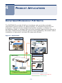
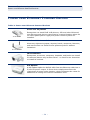
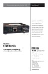
1
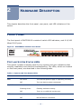
USER GUIDE
EZ SwitchTM 10/100
8-Port Fast Ethernet PoE Switch
SMCFS801P
EZ SwitchTM 10/100
User Guide
From SMC’s EZ line of low-cost workgroup LAN solutions
No. 1, Creation Road III,
Hsinchu Science Park,
30077, Taiwan, R.O.C.
TEL: +886 3 5638888
Fax: +886 3 6686111
April 2012
SMC-UG-0412-01
Information furnished by SMC Networks, Inc. (SMC) is believed to be accurate
and reliable. However, no responsibility is assumed by SMC for its use, nor for
any infringements of patents or other rights of third parties which may result
from its use. No license is granted by implication or otherwise under any patent
or patent rights of SMC. SMC reserves the right to change specifications at any
time without notice.
Copyright © 2012 by
SMC Networks, Inc.
No. 1, Creation Road III,
Hsinchu Science Park,
30077, Taiwan, R.O.C.
All rights reserved
Trademarks:
SMC is a registered trademark; and EZ Switch, TigerStack and TigerSwitch are
trademarks of SMC Networks, Inc. Other product and company names are
trademarks or registered trademarks of their respective holders.
WARRANTY AND PRODUCT REGISTRATION
To register SMC products and to review the detailed warranty statement, please
refer to the Support Section of the SMC Website at http://www.smc.com.
– 4 –
COMPLIANCES AND SAFETY
STATEMENTS
FEDERAL COMMUNICATION COMMISSION INTERFERENCE STATEMENT
This equipment has been tested and found to comply with the limits for a Class A
digital device, pursuant to part 15 of the FCC Rules. These limits are designed to
provide reasonable protection against harmful interference in a residential
installation. This equipment generates, uses and can radiate radio frequency
energy and, if not installed and used in accordance with the instructions, may
cause harmful interference to radio communications. However, there is no
guarantee that interference will not occur in a particular installation. If this
equipment does cause harmful interference to radio or television reception,
which can be determined by turning the equipment off and on, the user is
encouraged to try to correct the interference by one or more of the following
measures:
◆
Reorient or relocate the receiving antenna
◆
Increase the separation between the equipment and receiver
◆
Connect the equipment into an outlet on a circuit different from that to
which the receiver is connected
◆
Consult the dealer or an experienced radio/TV technician for help
This device complies with Part 15 of the FCC Rules. Operation is subject to the
following two conditions: (1) This device may not cause harmful interference,
and (2) this device must accept any interference received, including interference
that may cause undesired operation.
FCC Caution: Any changes or modifications not expressly approved by the
party responsible for compliance could void the user's authority to operate this
equipment.
NOTE: The manufacturer is not responsible for any radio or TV
interference caused by unauthorized modifications to this equipment.
Such modifications could void the user’s authority to operate the
equipment.
– 5 –
COMPLIANCES
AND
SAFETY STATEMENTS
CE MARK DECLARATION OF CONFORMANCE FOR EMI AND SAFETY (EEC)
SMC contact for these products in Europe is:
SMC Networks Europe,
C/Fructuós Gelabert 6-8, 2o, 2a,
Edificio Conata II,
08970 - Sant Joan Despí, Barcelona, Spain.
This information technology equipment complies with the requirements of the
Council Directive 89/336/EEC on the Approximation of the laws of the Member
States relating to Electromagnetic Compatibility and 73/23/EEC for electrical
equipment used within certain voltage limits and the Amendment Directive 93/
68/EEC. For the evaluation of the compliance with these Directives, the following
standards were applied:
RFI Emission:
Immunity:
LVD:
◆
Limit according to EN 55022:2010 AS/NZS CISPR 22:2009, Class A
◆
Limit for harmonic current emission according to EN 61000-32:2006+A1:2009+A2:2009
◆
Limitation of voltage fluctuation and flicker in low-voltage supply
system according to EN 61000-3-3:2008
◆
Product family standard according to EN 55024:2010
◆
Electrostatic Discharge according to IEC 61000-4-2:2008
◆
Radio-frequency electromagnetic field according to IEC 61000-43:2006+A1:2007+A2:2010
◆
Electrical fast trsnsient/burst according to IEC 61000-4-4:2010
◆
Surge immunity test according to IEC 61000-4-5:2005
◆
Immunity to conducted disturbances, Induced by radio-frequency
fields:IEC 61000-4-6:2008
◆
Power frequency magnetic field immunity test according to IEC
61000-4-8:2009
◆
Voltage dips, short interruptions and voltage variations immunity test
according to IEC 61000-4-11:2004
◆
EN60950-1:2006+A11:2009+A1:2010
– 6 –
COMPLIANCES
AND
SAFETY STATEMENTS
INDUSTRY CANADA - CLASS A
This digital apparatus does not exceed the Class A limits for radio noise
emissions from digital apparatus as set out in the interference-causing
equipment standard entitled “Digital Apparatus,” ICES-003 of the Department of
Communications.Cet appareil numérique respecte les limites de bruits
radioélectriques applicables aux appareils numériques de Classe A prescrites
dans la norme sur le matériel brouilleur: “Appareils Numériques,” NMB-003
édictée par le ministère des Communications.
PLEASE READ THE FOLLOWING SAFETY INFORMATION CAREFULLY BEFORE
INSTALLING THE SWITCH:
WARNING: Installation and removal of the unit must be carried out by qualified
personnel only.
◆
This guide is intended for use by network administrators who are
responsible for setting up and installing network equipment; consequently it
assumes a basic working knowledge of LANs (Local Area Networks).
◆
The unit must be connected to an earthed (grounded) outlet to comply with
international safety standards.
◆
Do not connect unit to an A.C outlet (power supply) without an earth
(ground) connection.
◆
The appliance coupler (the connector to the unit and not the wall plug)
must have a configuration for mating with an EN 60320/IEC 320 appliance
inlet.
◆
The socket outlet must be near to the unit and easily accessible. You can
only remove power from the unit by disconnecting the power cord from the
outlet.
◆
This unit operates under SELV (Safety Extra Low Voltage) conditions
according to IEC 60950. The conditions are only maintained if the
equipment to which it is connected also operates under SELV conditions.
– 7 –
COMPLIANCES
AND
SAFETY STATEMENTS
SAFETY PRECAUTIONS
Read the following information carefully before operating the device. Please
follow the following precaution items to protect the device from risks and
damage caused by fire and electric power:
◆
Use the power adapter that is included with the device package.
◆
Pay attention to the power load of the outlet or prolonged lines. An
overburdened power outlet or damaged cords and plugs may cause electric
shock or fire. Check the power cords regularly, if you find any damage,
replace it at once.
◆
Proper space for heat dissipation is necessary to avoid any damage caused
by device overheating. The ventilation holes on the device are designed for
heat dissipation to ensure that the device works normally. Do not cover
these ventilation holes.
◆
Do not put this device close to a place where a heat source exits or high
temperature occurs. Avoid placing the device in direct sunshine.
◆
Do not put this device close to a place which is damp or wet. Do not spill
any fluid on this device.
◆
Please follow the instructions in the user manual/quick install guide carefully
to connect the device to your PC or other electronic product. Any invalid
connection may cause a power or fire risk.
◆
Do not place this device on an unstable surface or support.
PRÉCAUTIONS DE SÉCURITÉ
Lisez attentivement les informations suivantes avant d’utiliser votre appareil.
Respectez toutes les précautions afin de protéger l’appareil des risques et dégâts
provoqués par un incendie et l’alimentation électrique :
◆
Utilisez exclusivement l’adaptateur d’alimentation fourni avec cet appareil.
◆
Faites attention à la puissance de charge de la prise de courant ou des
rallonges électriques. Une prise surchargée ou des cordons et des fiches
endommagés peuvent provoquer une électrocution ou un incendie. Vérifiez
régulièrement votre câble électrique. Si vous constatiez le moindre défaut,
remplacez-le immédiatement.
◆
Il est primordial de laisser suffisamment d’espace autour de l’appareil pour
permettre la dissipation de la chaleur et éviter les dégâts provoqués par une
– 8 –
COMPLIANCES
AND
SAFETY STATEMENTS
surchauffe de l’appareil. Les orifices de ventilation de l’appareil sont conçus
pour permettre la dissipation thermique et garantir le bon fonctionnement
de l’appareil. Ne couvrez jamais ces orifices.
◆
Ne placez pas cet appareil à proximité d’une source de chaleur ou dans un
endroit exposé à des températures élevées. Evitez également de l’exposer à
la lumière directe du soleil.
◆
Ne placez pas cet appareil à proximité d’un lieu humide ou mouillé. Prenez
garde à ne renverser aucun liquide sur cet appareil.
◆
Merci de suivre les instructions du manuel d'utilisateur / guide d’installation
rapide attentivement pour connecter l'appareil à votre PC ou à tout autre
produit électronique. Toute connexion non valide peut provoquer un
problème électrique ou un risque d'incendie.
◆
Ne placez pas cet appareil sur une surface ou un support instable.
SICHERHEITSMAßNAHMEN
Lesen Sie vor der Inbetriebnahme des Gerätes aufmerksam die nachstehenden
Informationen. Bitte befolgen Sie die nachstehenden Sicherheitsmaßnahmen,
damit das Gerät nicht beschädigt wird oder Gefahren durch Brand oder
elektrische Energie entstehen:
◆
Verwenden Sie nur das beim Gerät mitgelieferte Netzteil.
◆
Achten Sie auf die Last der Steckdose oder des Verlängerungskabels. Eine
überlastete Steckdose oder beschädigte Kabel und Stecker können
Stromschläge und Brand verursachen. Prüfen Sie die Netzkabel regelmäßig.
Ersetzen Sie sie umgehend, falls sie beschädigt sind.
◆
Achten Sie zur Vermeidung von Geräteschäden aufgrund von Überhitzung
darauf, dass genügend Freiraum zur Wärmeabfuhr vorhanden ist. Die
Belüftungsöffnungen am Gerät dienen der Wärmeabfuhr und damit der
Gewährleistung eines normalen Gerätebetriebs. Decken Sie diese
Belüftungsöffnungen nicht ab.
◆
Stellen Sie dieses Gerät nicht in der Nähe von Wärmequellen oder an Orten
mit hohen Temperaturen auf. Platzieren Sie das Gerät nicht im direkten
Sonnenlicht.
◆
Stellen Sie dieses Gerät nicht an feuchten oder nassen Orten auf. Achten
Sie darauf, keine Flüssigkeiten über dem Gerät zu verschütten.
– 9 –
COMPLIANCES
AND
SAFETY STATEMENTS
◆
Befolgen Sie die Hinweise im Benutzerhandbuch (bzw. in der Kurzanleitung)
zum Anschluß des Gerätes an einen PC oder ein anderes Elektrogerät.
Jegliche unzulässige Verbindung birgt die Gefahr von Stromschlägen und
Brandgefahr.
◆
Platzieren Sie dieses Gerät nicht auf einer instabilen Oberfläche oder
Halterung.
PRECAUCIONES DE SEGURIDAD
Lea la siguiente información detenidamente antes de utilizar el dispositivo. Siga
las indicaciones de precaución que se mencionan a continuación para proteger el
dispositivo contra riesgos y daños causados por el fuego y la energía eléctrica:
◆
Utilice el adaptador de alimentación incluido en el paquete del dispositivo.
◆
Preste atención a la carga de potencia de la toma de corriente o de los
alargadores. Una toma de corriente sobrecargada o líneas y enchufes
dañados pueden provocar descargas eléctricas o un incendio. Compruebe
los cables de alimentación con cierta frecuencia. Si detecta algún daño,
reemplácelos inmediatamente.
◆
Deje un espacio adecuado para que se disipe el calor y evitar así cualquier
daño en el dispositivo causado por sobrecalentamiento. Los orificios de
ventilación del dispositivo están diseñados para disipar el calor y garantizar
que dicho dispositivo funciona con normalidad. No tape estos orificios de
ventilación.
◆
No coloque este dispositivo cerca de un lugar donde haya una fuente de
calor o temperaturas elevadas. Evite exponer el dispositivo a la luz solar
directa.
◆
No coloque este dispositivo junto a un lugar húmedo o mojado. No derrame
ningún fluido sobre el dispositivo.
◆
Por favor, siga cuidadosamente las instrucciones que figuran en el manual/
guía de instalación rápida para conectar el dispositivo a su PC o a cualquier
otro producto electrónico. Cualquier conexión no válida podría causar riesgo
de descarga o de incendio.
◆
No coloque este dispositivo en una superficie o soporte inestable.
◆
Precauções de Segurança
– 10 –
COMPLIANCES
AND
SAFETY STATEMENTS
◆
Leia atentamente as seguintes informações antes de utilizar o dispositivo.
Respeite as seguintes indicações de segurança para proteger o dispositivo
contra riscos e danos causados por fogo e energia eléctrica:
◆
Utilize o transformador incluído na embalagem do dispositivo.
◆
Respeite a potência da tomada eléctrica e das extensões. Uma tomada
eléctrica sobrecarregada ou cabos e fichas danificadas podem causar
choques eléctricos ou fogo. Verifique regularmente os cabos de
alimentação. Caso algum se encontre danificado, substitua-o
imediatamente.
◆
É necessário deixar algum espaço livre em volta do dispositivo para
dissipação de calor, de forma a evitar danos causados pelo
sobreaquecimento do dispositivo. Os orifícios de ventilação do dispositivo
foram concebidos para dissipar o calor e assegurar que o mesmo funciona
normalmente. Não bloqueie esses orifícios de ventilação.
◆
Não coloque este dispositivo junto a fontes de calor ou em locais com
temperaturas elevadas. Evite colocar o dispositivo sob luz solar directa.
◆
Não coloque este dispositivo junto a locais molhados ou com humidade. Não
derrame líquidos sobre o dispositivo.
◆
Por favor siga atentamente as instruções do manual / guia de instalação
rápida para conectar o dispositivo ao seu PC ou a qualquer outro dispositivo
electrónico. Atenção que qualquer tipo de ligação inválida pode originar
risco de choque eléctrico ou de incêndio.
◆
Não coloque este dispositivo numa superfície ou suporte instáveis.
– 11 –
COMPLIANCES
AND
SAFETY STATEMENTS
– 12 –
ABOUT THIS GUIDE
PURPOSE
This guide details the hardware features of the switch, including the physical and
performance-related characteristics, and how to install the switch.
AUDIENCE
The guide is intended for use by network administrators who are responsible for
installing and setting up network equipment; consequently, it assumes a basic
working knowledge of LANs (Local Area Networks).
CONVENTIONS
The following conventions are used throughout this guide to show information:
NOTE: Emphasizes important information or calls your attention to
related features or instructions.
CAUTION: Alerts you to a potential hazard that could cause loss of data,
or damage the system or equipment.
WARNING: Alerts you to a potential hazard that could cause personal
injury.
REVISION HISTORY
This section summarizes the changes in each revision of this guide.
APRIL 2012 REVISION
This is the first revision of this guide.
– 13 –
ABOUT THIS GUIDE
– 14 –
CONTENTS
1
WARRANTY AND PRODUCT REGISTRATION
4
COMPLIANCES AND SAFETY STATEMENTS
5
ABOUT THIS GUIDE
13
CONTENTS
15
INTRODUCTION
17
Overview
2
17
Features
17
PoE Features
18
HARDWARE DESCRIPTION
19
Front Panel
19
Port and System Status LEDs
19
RJ-45 Ports
20
Rear Panel
20
AC Power Socket
3
20
INSTALLING THE SWITCH
21
Package Contents
21
Precautions
21
Safety Requirements
21
Location Requirements
22
Installation
22
Desktop Installation
23
Rack Installation
23
Connecting to Ground
25
Powering On
26
– 15 –
CONTENTS
Connecting Network Devices
4
A
27
Cabling Guidelines
27
Connecting to PCs, Servers, Hubs and Switches
27
PRODUCT APPLICATIONS
29
Department/Workgroup PoE Switch
29
Power over Ethernet Powered Devices
30
TROUBLESHOOTING
31
Diagnosing Switch Indicators
31
The Power LED is Off
31
The Link/Act LED is Off when a Device is Connected to the Corresponding Port
31
B
Power and Cooling Problems
31
Installation
32
SPECIFICATIONS
33
Physical Characteristics
33
– 16 –
1
INTRODUCTION
OVERVIEW
The EZ Switch 10/100 SMCFS801P PoE switch provide 8 or 10/100 Mbps autonegotiating RJ-45 ports. Each port on the switches support auto MDI/MDI-X,
which eliminates the need for crossover cables or uplink ports. The switches are
plug-and-play; any port can be connected to a server, a hub, or a switch, using
straight-through or crossover cable.
FEATURES
◆
Complies with IEEE 802.3 and IEEE 802.3u standards
◆
8 10/100 Mbps auto-negotiating RJ-45 ports supporting Auto-MDI/MDIX
◆
Supports PoE power up to 30 Watts on 4 ports, 15.4 Watts on 8 ports, or 7.5
Watts on 8 ports
◆
PoE total power budget 105W for all PoE ports
◆
Supports IEEE 802.3x flow control for full-duplex mode and backpressure
for half-duplex mode
◆
LED indicators for monitoring power, link, activity
◆
Rack-mountable steel case
◆
Support for Green Saving, which can save up to 60% of power consumption
– 17 –
CHAPTER 1 | Introduction
Overview
POE FEATURES
The SMCFS801P can provide up to 30 Watts of power to attached devices, such
as VoIP phones, wireless access points, surveillance cameras, etc, all over
existing Cat. 5 cables. The switch can deliver up to 30 Watts on 4 ports, or 15.4
Watts on 8 ports. This eliminates the need for individual power sources for
devices in the network, saving on costs for power cables and avoiding power
outlet availability issues. If the power demand exceeds the switch’s maximum
power budget.
– 18 –
2
HARDWARE DESCRIPTION
This chapter describes the front panel, rear panel, and LED indicators of the
switch.
FRONT PANEL
The front panel of SMCFS801P consists of switch LED indicators, and 8 10/100
Mbps RJ-45 ports.
Figure 1: SMCFS801P Switch Front Panel
PORT AND SYSTEM STATUS LEDS
This switch includes a display panel for key system and port indications that
simplify installation and network troubleshooting. The LEDs, which are located
on the front panel, are described in the following table.
Table 1: System and Port Status LEDs
LED
Condition
Status
PWR
On Green
The internal power supply is operating normally.
Off
The unit has no power connected.
On
Port has established a valid network connection.
Flashing Green
Flashing indicates activity.
Off
There is no valid link on the port.
On Green
A PoE device is connected.
Off
No PoE device connected.
LiK/ACT
PoE In Use
– 19 –
CHAPTER 2 | Hardware Description
Rear Panel
RJ-45 PORTS
The switch contains 8 100BASE-TX RJ-45 ports. All ports support automatic MDI/
MDI-X operation, so you can use straight-through cables for all network
connections to PCs or servers, or to other switches or hubs.
Each of these ports support auto-negotiation, so the optimum transmission
mode (half or full duplex), and data rate (10 or 100 Mbps) is selected
automatically.
Each port also supports IEEE 802.3x auto-negotiation of flow control, so the
switch can automatically prevent port buffers from becoming saturated.
REAR PANEL
The rear panel of the switch features a power socket.
Figure 2: SMCFS801P Switch Rear Panel
100-240VAC
100-24050-60Hz
VAC 1A
50 / 60 Hz
AC POWER SOCKET
Connect the female connector of the power cord here, and the male connector to
the AC power outlet. Make sure the voltage of the power supply meets the
requirement of the input voltage.
– 20 –
3
INSTALLING THE SWITCH
Before installing the switch, verify that you have all the items listed under
“Package Contents.” If any of the items are missing or damaged, contact your
local SMC distributor. Also be sure you have all the necessary tools and cabling
before installing the switch.
PACKAGE CONTENTS
The following contents should be found in your package:
◆
One SMCFS801P Switch
◆
One power cord
◆
This User Guide
◆
Rackmount Kit
◆
Four rubber foot pads
◆
SMC Warranty Card
PRECAUTIONS
To ensure a long-term and stable performance of the switch, pay attention to the
following before installation.
SAFETY REQUIREMENTS
◆
Before cleaning the switch, disconnect the power supply. Do not clean the
switch using a wet cloth, and never use any other liquid for cleaning.
– 21 –
CHAPTER 3 | Installing the Switch
Installation
◆
Take waterproof measures during storage, transportation and operation of
the equipment.
◆
Use only the power cord provided with the switch.
◆
Make sure the voltage of the power supply meets the requirement of the
input voltage of the switch.
◆
Do not push any objects into the openings of the switch.
◆
Ensure the vent holes are well ventilated and unblocked.
◆
Do not open or remove the cover of the switch.
LOCATION REQUIREMENTS
When you choose a location for the switch, follow these guidelines:
◆
Install the switch on a flat and stable surface that can support the entire
weight of the switch with all fittings.
◆
Locate the switch far from strong electromagnetic field generators (such as
motors), vibration, dust, and direct exposure to sunlight.
◆
To ensure adequate air flow around the switch. At least 10 cm (4 inches) of
space at the front and rear of the switch is needed for ventilation.
◆
Make sure that the switch will be accessible and that the cables can be
easily connected.
◆
Position the switch away from water and moisture sources, be sure to
provide an acceptable temperature and humidity operating environment.
INSTALLATION
This switch can be either installed in a standard 19-inch mountable rack or
located on a desktop.
CAUTION: Please unplug the power cord before installing or removing
the switch.
– 22 –
CHAPTER 3 | Installing the Switch
Installation
DESKTOP INSTALLATION
To install the switch on the desktop, follow these steps:
1. Set the switch on a flat surface strong enough to support the entire weight
of the switch with all fittings.
2. Remove the adhesive backing papers from the rubber feet.
3. Turn the switch over and attach the supplied rubber feet to the recessed
areas on the bottom at each corner of the switch.
Figure 3: Attaching Rubber Feet
4. Upturn the switch and set in the desired location, making sure there is
enough ventilation space on all sides for proper air flow
5. Connect the switch to a power source with the provided power cord. See
“Powering On” on page 26.
CAUTION: Avoid placing anything heavy on the switch.
RACK INSTALLATION
To install the switch in an EIA standard-sized, 19-inch rack, follow the
instructions described below:
– 23 –
CHAPTER 3 | Installing the Switch
Installation
1. Secure the supplied rack-mounting brackets to each side of the switch with
supplied screws, as illustrated in the following figure.
Figure 4: Attaching Brackets
– 24 –
CHAPTER 3 | Installing the Switch
Installation
2. Use suitable screws (not provided) to secure the brackets to the rack, as
illustrated in the following figure.
Figure 5: Mounting the Switch
3. Connect the switch to a power source with the provided power cord. See
“Powering On” on page 26.
CONNECTING TO GROUND
Connecting the switch to ground protects against lightning over-voltage and
over-current of the switch, which is also a necessary measure to protect the
body from electric shock.
In different environments, the switch may be grounded differently. The following
instructs you to connect the switch to ground through the power cord. Connect
the switch to ground in the best way according to your specific operating
environment.
– 25 –
CHAPTER 3 | Installing the Switch
Installation
CONNECTING TO GROUND THROUGH THE POWER SUPPLY
If the switch is installed in a normal environment, it can be grounded through
the PE (Protective Earth) wire of the AC power supply, as shown in the following
figure.
Figure 6: Connecting to Ground Through the Power Supply
100-240
VAC
50 / 60
Hz
NOTE: The figure illustrates the application and principle. The power
plug in the package and the socket in your situation will comply with
regulations in your country, so they may differ from the figure above.
NOTE: If you intend to connect the switch to ground through the PE
(Protective Earth) wire of the AC power cord, make sure the PE wire in
the electrical outlet is well grounded in advance.
POWERING ON
The SMCFS801P switch is powered by connecting to an AC power supply using a
power cord. When powering on the switch, it automatically initializes and the
LED indicators respond as follows:
1. All of the LED indicators flash momentarily for one second, which represents
a resetting of the system.
– 26 –
CHAPTER 3 | Installing the Switch
Connecting Network Devices
2. The Power LED indicator turns on green.
CONNECTING NETWORK DEVICES
This switch is designed to be connected to 10, or 100 Mbps network cards in PCs
and servers, as well as to other switches and hubs.
CABLING GUIDELINES
The RJ-45 ports on the switch support automatic MDI/MDI-X pinout
configuration, so you can use standard straight-through twisted-pair cables to
connect to any other network device (PCs, servers, switches, routers, or hubs).
Each device requires an unshielded twisted-pair (UTP) cable with RJ-45
connectors at both ends. Use Category 5 or better for 100BASE-TX connections,
and Category 3 or better for 10BASE-T connections.
CONNECTING TO PCS, SERVERS, HUBS AND SWITCHES
1. Attach one end of a twisted-pair cable segment to the device’s RJ-45
connector.
2. Attach the other end of the cable segment to an available port on the
switch.
Make sure each twisted pair cable does not exceed 100 meters (328 ft) in
length.
3. As each connection is made, the relevant port LED (on the switch)
corresponding to each port will turn on green to indicate that the connection
is valid.
– 27 –
CHAPTER 3 | Installing the Switch
Connecting Network Devices
– 28 –
4
PRODUCT APPLICATIONS
DEPARTMENT/WORKGROUP POE SWITCH
The SMCFS801P provides 8 PoE port interfaces and can build a centrallycontrolled IP phone system, IP camera system, or wireless AP group for the
enterprise. Cameras can be installed around the company or campus for
surveillance needs, or wireless APs can build a wireless roaming environment in
the office. Without being limited by power-socket availability, the switch makes
installation of cameras or wireless APs easy and efficient.
Figure 7: Applications
PoE IP Camera
Non-PoE IP Camera
PoE
DC
PoE Spiltter
PoE
SMCFS801P
PoE Wireless AP
PoE
PoE
PoE IP Phone
Centre of Surveillance
100BASE-TX UTP
100BASE-TX UTP With PoE
Power Line (DC)
– 29 –
CHAPTER 4 | Product Applications
Power over Ethernet Powered Devices
POWER OVER ETHERNET POWERED DEVICES
Table 2: Power over Ethernet Powered Devices
Voice over IP phones
3~5 Watts
Enterprises can install PoE VoIP phones, ATA and other Ethernet/
non-Ethernet end-devices connected to a central location where an
un-interruptible power supply and power control system are
installed.
Wireless LAN Access Points
Museums, sightseeing spots, airports, hotels, campuses, factories,
and warehouses can install access points anywhere without
limitations.
6~12 Watts
IP Surveillance
Enterprises, museums, campuses, hospitals, and banks can install
IP cameras without any location limits - no need for an electrician
to install AC sockets.
10~12 Watts
PoE Splitter
A PoE splitter splits the PoE 48 VDC from the Ethernet cable into a
5/12V DC power output. It frees device deployment from the
restrictions of power outlet location, which eliminates the costs for
additional AC wiring and reduces installation time.
3~12 Watts
– 30 –
A
TROUBLESHOOTING
DIAGNOSING SWITCH INDICATORS
THE POWER LED IS OFF
◆
Make sure the AC power cord is connected to the switch and power source
properly.
◆
Make sure the power source is ON.
THE LINK/ACT LED IS OFF WHEN A DEVICE IS CONNECTED TO THE
CORRESPONDING PORT
◆
Make sure that the cable connectors are firmly plugged into the switch and
the device.
◆
Make sure the connected device is turned on and working properly.
◆
The cable must be less than 100 meters long (328 feet).
◆
Check the port on the attached device and cable connections for possible
defects. Replace the defective cable if necessary.
POWER AND COOLING PROBLEMS
If the power indicator does not turn on when the power cord is plugged in, you
may have a problem with the power outlet, power cord, or internal power
supply. However, if the unit powers off after running for a while, check for loose
power connections, power losses or surges at the power outlet. If you still
cannot isolate the problem, the internal power supply may be defective.
– 31 –
APPENDIX A | Troubleshooting
Installation
INSTALLATION
Verify that all system components have been properly installed. If one or more
components appear to be malfunctioning (such as the power cord or network
cabling), test them in an alternate environment where you are sure that all the
other components are functioning properly.
– 32 –
B
SPECIFICATIONS
PHYSICAL CHARACTERISTICS
STANDARDS
IEEE 802.3 10BASE-T
IEEE 802.3u 100BASE-TX
TOPOLOGY
Star
PROTOCOL
CSMA/CD
DATA TRANSFER RATE
Ethernet: 10 Mbps (half duplex)
Ethernet: 20 Mbps (full duplex)
Fast Ethernet: 100 Mbps (half duplex)
Fast Ethernet: 200 Mbps (full duplex)
NETWORK MEDIA (CABLE)
10BASE-T: UTP Category 3, 4, 5 cable (maximum 100 m)
EIA/TIA-568 100 STP (maximum 100 m)
100BASE-TX: UTP Category 5, 5e cable (maximum 100 m)
EIA/TIA-568 100 STP (maximum 100 m)
NUMBER OF PORTS
8 10/100 Mbps auto-negotiating RJ-45 PoE ports
– 33 –
APPENDIX B | Specifications
Physical Characteristics
LED INDICATORS
System: PWR
Ports: LNK/ACT, PoE In Use
TRANSFER METHOD
Store-and-Forward
MAC ADDRESS LEARNING
Automatically learning, automatically aging
FRAME FILTER RATE
10Mbps:14880pps
100Mbps:148800pps
FRAME FORWARD RATE
10Mbps:14880pps
100Mbps:148800pps
SWITCHING DATABASE
2K MAC address entries
BUFFER MEMORY
440K Bits (55K Bytes)/Device
SWITCHING
1.6 Gbps
CAPACITY
THROUGHOUT
1.2 Mpps
– 34 –
APPENDIX B | Specifications
Physical Characteristics
POE FEATURES
Supports IEEE 802.3af/at
Supported Power to PD: 30W
Total PoE Budget: 105W (Total Power: 130W)
PoE Ports: 8 ( Ports 1-8)
POWER SUPPLY
AC input : 100~240V, 50/60Hz
DC output: DC 50V, 2.5A
DIMENSIONS
28 x 17.9 x 4.45 cm (11 x 7.05 x 1.75 in.)
WEIGHT
1.72 Kg (3.80 lbs)
TEMPERATURE
Operating: 0 to 50 °C (32 to 122 °F)
Storage: -40 to 70 °C (-40 to 158 °F)
HUMIDITY
Operating: 5% to 90% (non-condensing)
Storage: 10% to 90% (non-condensing)
– 35 –
APPENDIX B | Specifications
Physical Characteristics
– 36 –
SMC NETWORKS TECHNICAL SUPPORT
From Singapore in English and
(Mon.-Fri. 9AM to 5 PM)
Tel: +65-63387667, Ext. 4
From the United Arab Emirates in English (Sun.-Thu. 9AM to 6 PM)
563 8888
668 6 1 1 1
Tel: +971 800 222866/+971 4 3564810
From U.S.A. and Canada (24 hours a day, 7 days a week)
Tel: +1 (800) SMC-4-YOU/+1 (949) 679-8000 Fax: +1 (949) 679-1481
su www.smc.com
www.smc-asis.com
www.smcnetworks.co.kr
SMCFS801P
www.edge-core.com/ www.smc.com
150200062800A R02
20 Mason • Irvine, CA 92618 • Phn: 949-679-8000 • www.smc.com