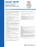
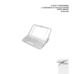
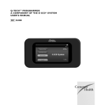
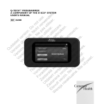
1
User Guide
CEPAS
CEPAS™
Cardiac ElectroPhysiology Analysis System
User Guide
By Andrew Madry
Cuoretech Pty Ltd
www.cepas.com.au
1
User Guide
CEPAS
Table of Contents
1
2
Introduction ...................................................................................................................................5
1.1
Navigating this Guide ...............................................................................................................5
1.2
Overview of the CEPAS Front Panel ...........................................................................................5
1.3
CEPAS Terminology..................................................................................................................7
1.4
LabVIEW Terminology ............................................................................................................10
1.5
Text Formating in this User Guide ...........................................................................................10
Mesh File......................................................................................................................................11
2.1
Understanding Mapping.........................................................................................................11
2.2
Setting up the Mesh File .........................................................................................................11
2.2.1
Mesh Header..................................................................................................................11
2.2.2
Channel Labels ...............................................................................................................13
2.2.3
Physical Coordinates .......................................................................................................13
2.2.4
Mesh Nodes ...................................................................................................................13
2.2.5
Order of Channels...........................................................................................................14
2.3
3
2.3.1
Dummy Points ................................................................................................................14
2.3.2
Mesh File and Data File Channel Order ............................................................................15
2.3.3
Mesh File Scale Factor.....................................................................................................16
2.3.4
Mesh File for Arbitrarily Positioned Channels ...................................................................17
2.3.5
Using the Mesh File Channel Label to Internally Re-order the Data ....................................17
2.4
Selecting Channels for Display in CEPAS...................................................................................19
2.5
Other Mesh File Setup Information.........................................................................................19
Electrophysiology Data Files..........................................................................................................20
3.1
Loading a File.........................................................................................................................20
3.2
Data File Formats ...................................................................................................................20
3.2.1
CEPAS ............................................................................................................................20
3.2.2
NavX Classic DxL .............................................................................................................20
3.3
4
Advanced Mesh File Settings ..................................................................................................14
Internal Program Data Format ................................................................................................21
Configuration File (ini File) Settings ...............................................................................................23
4.1
Mesh Files .............................................................................................................................23
4.2
Data Files...............................................................................................................................23
4.3
CEPAS File Format..................................................................................................................23
4.4
Buffer Settings .......................................................................................................................24
2
User Guide
5
Time Domain Filtering...................................................................................................................25
5.1
Default Settings .....................................................................................................................25
5.2
High Pass Filtering..................................................................................................................26
5.3
Low Pass Filter.......................................................................................................................27
5.4
Digital Filter Designs...............................................................................................................30
5.4.1
6
CEPAS
Filter Time-Shift..............................................................................................................30
CEPAS Algorithms .........................................................................................................................31
6.1
Basic Activation Detection......................................................................................................31
6.2
Fractionation Index................................................................................................................34
6.3
Fractionation Index References...............................................................................................34
6.4
Adjusting Settings for Fractionation Index Calculation..............................................................35
6.5
Phase ....................................................................................................................................38
6.5.1
Phase Method 1 – Phase Template ..................................................................................38
6.5.2
Phase Method 2 - Hilbert Transform................................................................................38
6.6
FFT ........................................................................................................................................39
6.7
Organisation Index.................................................................................................................39
6.8
Regularity Index.....................................................................................................................39
6.9
Voltage..................................................................................................................................39
6.10
Shannon Entropy ...................................................................................................................39
6.11
Plug-In...................................................................................................................................39
7
Isochronal Map.............................................................................................................................40
8
The Detection Manager ................................................................................................................45
9
8.1
Detection Manager Width......................................................................................................45
8.2
Automatically Marking Detections ..........................................................................................47
8.3
Manual Adjustment of Detections...........................................................................................48
8.4
Exporting Activations .............................................................................................................49
8.5
Importing Detections .............................................................................................................50
Animating the Map using Phase ....................................................................................................51
9.1
Phase Mapping......................................................................................................................51
9.2
Set Colour Scale .....................................................................................................................51
9.3
Computing Phase ...................................................................................................................51
9.4
Example ................................................................................................................................52
9.5
Creating the Animation ..........................................................................................................58
10 QRST Subtraction..........................................................................................................................63
3
User Guide
CEPAS
10.1
Instructional Example.............................................................................................................63
10.2
Summary...............................................................................................................................73
11 CEPAS Real Time Mode .................................................................................................................74
11.1
Real Time Buffer Width ..........................................................................................................77
12 Additional Notes on Use of LabVIEW Controls ...............................................................................79
12.1
Incrementing/Decrementing Numeric Controls........................................................................79
12.2
Channel Label or Channel Index Controls.................................................................................79
12.3
Graph Controls ......................................................................................................................79
4
User Guide
1
CEPAS
Introduction
CEPAS is a sophisticated program for analysis of cardiac electrophysiology signals. Developing the system
has involved a trade-off between providing the ability to delve into the data, to obtain insights into cardiac
electrical behaviour, and making it as simple to use as possible. Therefore some detailed knowledge of
how the program works is required to make the optimum use of the program’s capabilities.
This User Guide is continually being developed and is updated regularly.
1.1
Navigating this Guide
The easiest way to get started with CEPAS is to run through examples provided as tutorials. These tutorials
provide step by step instructions, starting from loading a Data File and then running through application of
a specific analysis method.
To get the full benefit of all the features in CEPAS the rest of this manual provides in-depth information
about how to work with signals and apply the in-built algorithms.
The following chapters describe the logical steps that are taken when analysing a dataset:
•
Setting up the Mesh File;
•
Loading the Data File;
•
Filtering the Data;
•
Applying Analysis Algorithms;
•
Animating a Parameter to visualise wavefront propagation;
•
Exporting data to use in other applications.
CEPAS also has a Real Time mode where data from specific mapping systems can be streamed live into
CEPAS. There is a separate section describing this mode.
1.2
Overview of the CEPAS Front Panel
The CEPAS Main Front Panel is shown in Figure 1. Specific regions of the Front Panel, which will be referred
to throughout the User Guide, are identified in Figure 1.
5
User Guide
CEPAS
Map Display
Total Data Graph
Reference Channel Electrogram Graph
Analysis Tabs
Test Channel Elegctrogram Graph
FFT Display
Main
Elegctrogram
Graph
Side Tabs
Figure 1. CEPAS Main Front Panel.
A detailed description of terms used to describe the parts of the User Interface is found in the next section.
6
User Guide
1.3
CEPAS
CEPAS Terminology
This section provides a detailed explanation of CEPAS terminology.
Where a term is capitalised (or in a special font) in the text of this user guide it may be a term that has
special meaning in the CEPAS context. A detailed description of specific CEPAS terms may be found in
Table 1.
Term
Main Front Panel
Total Data Graph
Data Segment
Explanation
Additional Notes
This is the window that appears upon program launch and
which the user will spend most time viewing, shown in
Figure 1. Also called Main Panel.
This is the graph on the CEPAS front panel showing on its X
Scale the full time extent of the data file that has been
loaded. This may be something short like 4 seconds, for a
typical exported section from an EP Recording system, or it
could be many minutes of data from a study.
Cursors (yellow – left, red - right) on this graph show the
extent of the currently “viewed” data from the data file.
Other “Front Panels” will appear (eg
pop-up) depending on specific
operations selected.
Dots are shown on the Total Data graph
spaced at one hundredth of the total
data file duration apart. If you zoom in
on the Total Data graph these dots help
give an idea of by how much it is
zoomed.
This graph is disabled in the Real Time Mode.
This is the block or chunk of data read from a file and
loaded into memory for immediate use. A Segment
contains all channels and a fixed number of time samples
corresponding to a specified time duration. The Segment
size, in seconds, is read from the CEPAS.ini file key named
BufferSize(sec). The default value is 4 seconds.
The value can also be changed using a control on the Front
Panel (Real Time tab). However a change to this value only
takes effect when a new file is loaded.
Note if a new file is loaded and it has a
different sampling frequency then
Buffer size may not be set
appropriately. Need to confirm.
Note that the Segment is also called the Buffer in
documentation. However buffer is actually a more general
term. The term data block is also used but this also has a
specific meaning.
Display View
Main Electrogram
Display Graph
Parameter
Algorithm
Settings
To get the length, in samples, of the Segment, the buffer
duration (in seconds) is divided by the specified sampling
interval (in seconds). The sampling interval value is also
read upon file load. If the division is not exact the nearest
value is used.
This is the data from the current Data Segment that is
currently “in view” in the Main Panel’s Electrogram Display
Graph. This width is set by the cursors on the Total Data
graph. The Display View has a specific length in samples
(corresponding to a time duration). This will always be
equal to or less than the length of the Data Segment that is
currently loaded. Note that it is the Display View, rather
than the Segment, that is used for processing.
This is the multi-channel electrogram display on the left
hand side of the CEPAS front panel. The graph has up to 8
plots that are simultaneously displayed in this graph. Each
plot has a different colour. Dots with the same colour as
the plots appear on the Map display to identify the
respective physical measurement location.
A Parameter is the quantity computed from the measured
data for each channel and displayed in colour on the Map.
An algorithm is used to compute the Parameter based on
the input time series data and various settings.
The mathematical method or equation used to calculate a
Parameter from input data.
Term used for the inputs to an algorithm that affect the
This may also be also referred to as the
“Data View”.
Note that the Detection Manager
works with the Display View which may
be a subset of the Data Segment.
Note that the term parameter can have
many usages. The description provided
here is to define it in the CEPAS
context.
7
User Guide
Term
Map Display
map
Real Time Mode
Detection
Signal
CEPAS
Explanation
result. The Settings are also called the algorithm input
variables.
Noun: This is the area on the CEPAS main panel, at the top
right, where the specified Parameter, computed for each
Display Channel, is shown in its relative spatial location.
Verb: Mapping is the process of registering the calculated
Parameters to spatial locations.
CEPAS switches to this mode when the user presses the
“Init” button on the front panel (also the “i” key on
keyboard). The Total Data graph is disabled in this mode.
The system is then ready to read data from the real time
stream.
Access to the Real Time Mode can be disabled via a
configuration file setting. This can be convenient if it is not
being used.
Detection (verb) is the process of determining the location
in time of electrogram fiducial points. The fiducial points
correspond to features of interest in the signal that a
recurrent. For example it may be activation times
(considered to be the time of cell depolarisation) in each
channel recording. There are other features that may be of
interest for specific analysis.
The set of time points are the Detections (noun).
These detections may be referred to as activations or
activation times in this manual as this is a typical usage. It
is important to note that detections are not limited to
marking activations. Detection is the more general term as
it could refer to detection of other features in the data
rather than cell depolarisation.
The term signal is used in several contexts. It can refer to
the actual electrical signal measured from each electrode
in contact with the epicardium or endocardium.
A pair of signals is input to the biomedical amplifier. The
reference electrode also provides a signal.
In a more general sense the term signal may be used to
refer to the signal output by the biomedical amplifier that
is used for subsequent mathematical analysis. The output
of the amplifier may be a unipolar or bipolar signal,
depending on the amplifier reference potential. Signals are
unipolar if they all have the same reference
signal/electrode.
Measurement
Signal
Electrogram
Bipolar
Electrogram
The digitised version of the output signal from each
amplified channel is what is stored in the Data File. See
definition of Channel below.
Definition as per Signal. This term is used when it is
necessary to distinguish it with the term Display Channel.
In CEPAS the Display Channel is always obtained from two
electrode signals.
A time domain signal measured from an electrode. The
electrode can be unipolar, ie referenced to a potential at
some other location, or bipolar which is derived from a pair
of closely spaced sensing positions. The measurement
quantity is voltage.
This is an electrogram where the measurement at one
sensing location is referenced to a nearby sensing location.
Effectively it is the potential difference between two
nearby locations.
Additional Notes
Need to check what buffer size is used
in this case. Is it the Segment or View?
This is akin to detection of a target.
There are multiple detections in the
time series.
Note that some systems may have pairs
of electrodes spaced close together, in
order to form bipolar channels.
However the signals from these closely
spaced electrodes may be individually
amplified (with respect to a common
reference electrode) and the bipolar
signal formed mathematically by
subtraction.
One of the signals may be zero value in
the case of Unipolar data.
8
User Guide
Term
Unipolar
Electrogram
Channel
CEPAS
Explanation
Additional Notes
Note that the electrogram amplifier system can directly
provide the bipolar electrogram. The Bipolar Electrogram
can also be derived by subtracting two closely spaced
unipolar electrogram measurements where the same
reference is used for each.
This is an electrogram measurement made referenced to a
remote reference electrode location.
Channels are the signals that are used as input for analysis
and from which Parameters are computed and then
displayed on the Map. Each Channel may be obtained
from unipolar or bipolar signals.
A Display Channel (see below) takes up a display slot on
the main graph display.
Each channel is identified by a Channel Index. Channel
Indices start numbering from 0. The Channel data is made
up from a pair of signals. If it is a bipolar channel then it is
the difference of two unipolar electrograms. If it is
unipolar the second electrogram is arbitrarily set to zero so
the difference is the same as the original.
Note that it is possible that the
amplifier system provides bipolar
signals directly. In this case a bipolar
signal is equivalent to a unipole as far
as CEPAS is concerned. The Display
Channel will be made up by setting the
alternate channels to zero value so the
difference between adjacent channels
is the same.
Three plots may be displayed for each Display Channel, ie
the two unipolar electrograms (shown in grey) and the
resulting bipolar electrogram which is allocated a plot
colour, which identifies its location with a dot on the Map
Display. Within the CEPAS program each Channel consists
of an array with 2 rows.
Display Channel
Mesh
Patch
Plaque
Mesh Scale Factor
Note that the term channel may also be used in a more
general sense.
If the term Display Channel is used by itself then it is
assumed to refer to the Channels displayed in the Main
Electrogram Graph and specifically identified on the Map
Display.
The Display Channel plot is calculated from the two signals
associated with each channel.
The construct that CEPAS uses to determine which
electrodes are neighbours to which.
The term patch is used in the context of the Mesh File. A
Patch is a logical grouping of electrodes, eg the group of
channels associated with a mapping device such as an
epicardial mapping plaque or a basket catheter are part of
the same patch. Electrodes on one linear catheter can be
considered as on the same patch.
A chapter of this manual is dedicated to
construction of Mesh Files.
There may be data from multiple patches in the same
recording.
Same as Patch, but this term is generally used in epicardial
mapping.
The Mesh Scale Factor is used to scale between the
representation on the Map Display and the real electrode
positions. The scale factor is expressed in metres per Map
Display unit. In some cases display units can be exactly the
same as millimetres. If each display unit corresponds to
1mm then the scale factor is 0.001. This is the assumed
default value if no scale factor is provided in the Mesh File.
Table 1. CEPAS Terminology.
9
User Guide
1.4
CEPAS
LabVIEW Terminology
CEPAS is written using LabVIEW from National Instruments and some references are made to LabVIEW
specific terminology. LabVIEW terms that the user may not be familiar with are explained in the
Terminology Table 2 below.
Term
Front Panel
Front Panel Control
Front Panel Indicator
Dialog
Graph
VI
Chart
Description
The Window of a LabVIEW progam that appears with Controls, Indicators and Graphs for the User
to work with.
LabVIEW terminology for an object on the user interface where a value is input by the user.
LabVIEW terminology for an object on the user interface that is not settable by the user, but
provides an output result.
A Windows panel that pops up in response to user action.
Type of display that shows multiple Plots of data.
This is the term used in LabVIEW for a LabVIEW subroutine. VI stands for Virtual Instrument.
Same as a Graph but the data scrolls as it is received in Real Time
Table 2. LabVIEW Terminology.
1.5
Text Formating in this User Guide
In this User Guide text highlighted in dark red refers to a specific CEPAS menu item or tab. Text in olive
green refers to a specific LabVIEW front panel control or indicator. The text colouring will be used
specifically when the narrative involves instructions for the user to press or select a particular control and
to highlight that the words in the User Guide text refer to the specific control or indicator (as opposed to
being descriptive).
The Courier Font is used to indicate specific computer settings.
Notes on internal CEPAS program implementation are provided for reference and are contained in a text
box. For most users these sections can be ignored.
Names that are capitalised, eg Data File, are used when the combination of words has a special meaning in
the CEPAS context. These words may be specifically defined in the Terminology table.
10
User Guide
2
Mesh File
2.1
Understanding Mapping
CEPAS
Mapping is the process of registering a value, calculated for each signal channel, on a graphical
representation of the physical location in space where the signal was acquired from.
Currently in CEPAS the graphical representation is in 2D and shown in the Map Display (see Figure 1).
The CEPAS Mesh File identifies where each channel in a Data File is physically located. The original location
is on some cardiac mapping device(s). Example devices are:
•
•
Intraoperative mapping devices like mapping patches/plaques/socks;
Multiple multi-element catheters as recorded by the EP lab recording system.
CEPAS needs a specific Mesh File appropriate for the Data File so that it can create a Map. The Mesh File
provides the physical coordinates for each channel in coordinates that are scaled to suit the CEPAS Map
Display space on the Front Panel. The Mesh File can also provide Labels for each channel to identify them,
for those data formats that do not incorporate a Label.
Note that Data Files can still be loaded without a specific Mesh File. However in this case there is no
possibility of creating a Map. There are also no Channel Labels.
Note perhaps I should auto label in this case.
Analysis, such as FFT of electrograms, can still be carried out on such data.
Note that CEPAS still requires that some Mesh File is always loaded. There is a “Dummy” Mesh File, which
does not specify any measurement positions, which can be used if this is the case.
2.2
Setting up the Mesh File
The Mesh File is an ASCII text file that can be created in a program such as Notepad or Excel. It is tab
delimited.
2.2.1 Mesh Header
The Mesh File consists of a header section providing information on the grouping of channels within the
Data File that it is to be used with.
The first line specifies the number of groups of channels, ie patches, that are in the file. The number within
each group is identified on subsequent lines. Information on each group follows the first line with the first
word of the line being “patch1”, followed by a tab and then the number of channels in that group. Next is
“patch2” up to patchN”, where N is the number of groupings.
An example Mesh File for an experimental cell culture electrode arrangement is shown below. The main
measurement array is the first patch. In this case the second patch consisted of 4 electrodes that did not
have any valid data but were still measured by the amplifier system and were included in the data file. A
dummy patch of 4 electrodes was set up for these channels.
11
User Guide
CEPAS
Example Mesh File:
2 0.00025
patch1
patch2
1 8.5
2 8.5
3 8
4 12.5
5 10.5
6 12.5
7 8.5
8 6.5
9 6.5
10 11
11 10.5
12 10.5
13 12.5
14 12.5
15 6.5
16 4.5
17 8.5
18 8.5
19 10.5
20 14.5
21 14.5
22 14.5
23 4.5
24 4.5
25 6.5
26 6.5
27 12.5
28 17.5
29 17.5
30 14.5
31 1.5
32 1.5
33 4.5
34 6.5
35 10.5
36 12.5
37 12.5
38 14.5
39 10.5
40 6.5
41 8.5
42 8.5
43 11
44 10.5
45 10.5
46 14.5
47 6.5
48 4.5
49 8.5
50 8.5
51 10.5
52 4.5
53 10.5
54 12.5
55 6.5
56 8.5
57 6.5
58 8
59 12.5
60 12.5
61 20
62 21
63 22
64 23
60
4
18.5
20.5
25.5
22.5
18.5
18.5
14.5
18.5
20.5
25.5
22.5
16.5
16.5
14.5
16.5
18.5
16.5
22.5
20.5
18.5
16.5
14.5
14.5
16.5
14.5
22.5
20.5
15
12
12.5
15
12
12.5
6.5
4.5
10.5
12.5
10.5
6.5
12.5
12.5
6.5
1.5
8.5
12.5
8.5
10.5
8.5
10.5
4.5
14.5
10.5
10.5
8.5
8.5
8.5
4.5
1.5
4.5
6.5
2.5
2.5
2.5
2.5
3
3
3
5
4
5
3
2
2
4
4
4
5
5
2
1
3
3
4
6
6
6
1
1
2
2
5
7
7
6
0
0
1
2
4
5
5
6
4
2
3
3
4
4
4
6
2
1
3
3
4
1
4
5
2
3
2
3
5
5
0
0
0
0
8
9
11
10
8
8
6
8
9
11
10
7
7
6
7
8
7
10
9
8
7
6
6
7
6
10
9
6
5
5
6
5
5
2
1
4
5
4
2
5
5
2
0
3
5
3
4
3
4
1
6
4
4
3
3
3
1
0
1
2
1
2
3
4
A second value appears on the first line of the Mesh File, after the number of patches 2, in the example
above. This value is optional and will be explained later.
The electrodes, or measurement positions for each channel, on the CEPAS Map Display, are as shown in
Figure 2 below for the Mesh File example above:
12
User Guide
CEPAS
Figure 2. Map Display for cell culture electrode configuration.
The dummy patch is set in any location away from the main patch. In the example above it is the group of
4 electrodes in a line on the bottom right of Figure 2.
2.2.2 Channel Labels
The Mesh File also gives a name to each Channel. This is called the “Channel Label”.
The first column in the Mesh File is the Channel Label. This is any ASCII text to identify the channels. It
should be kept short and to less than 5 characters, otherwise there is not room on the CEPAS Front Panel
for the Label. In the example above a simple numbering scheme labelling the Channels numerically from 1
to 64 is used. Note that this should not be confused with the Channel Index, which in this case will be
0..63.
Channels are referenced inside the CEPAS program by the channel index. This is the LabVIEW internal
array’s row index and is zero based, ie ranging from 0..N-1, where N is the number of channels. The Front
Panel controls: EGM Ch, Ref Ch and Test Ch use this channel index, rather than the Channel Label, to select
specific channels.
2.2.3 Physical Coordinates
The next two columns in the Mesh File are the x and y physical coordinates, scaled and offset, to suit the
Map Display. They are in the units of the Map Display which has graticules spaced 5 Display Units apart.
The Map Display space is approximately 70 units wide by 27 units high. This is very important to note, ie
that the Mesh File Map coordinates are in units of the Map Display and NOT the actual coordinate system
of the mapping device, eg in millimetres.
2.2.4 Mesh Nodes
The Mesh File provides the coordinates of each node within a “Mesh”. The Mesh nodes form a grid which
is independent of actual physical location. This Mesh grid is required to determine which electrodes are
the neighbouring ones to any specified electrode. It is not necessary that they be the physically closest
(although this is normally the case). The neighbouring electrodes and their mapped values are the ones
that are used for the interpolation process which colours in between the nodes on the Map.
13
User Guide
CEPAS
The 4 th and 5th columns are the integral x and y indices of the “mesh node”. The Mesh can be considered
like a net cast over the measurement locations. The net is stretched and shrunk to fit to the actual
measurement positions when the spacing is not regular, ie equi-spaced. The Mesh defines which points
are neighbours to others. Thee nodes must be correct in order to create a map correctly.
2.2.5 Order of Channels
The order of the channels as they appear in the Mesh File (ie row by row in the *.txt Mesh File) MUST
correspond to the order of these channels as they are in the Data File. In other words the format of the
Data File dictates how we set up the Mesh File.
The CEPAS “Read Mesh File” VI generates an array index for each individual channel as it appears in the Mesh File and
this index is then used to index into the channels in the internal data array.
Note however there are some exceptions to this rule for some specific data formats that are explained in a
section below.
2.3
Advanced Mesh File Settings
2.3.1 Dummy Points
Channel Labels in the first column of the Mesh File can be either numeric only or alphanumeric (ie
combined numeric and alphabetic characters). If the Channel Labels are numeric only (which CEPAS will
detect on load of the Mesh File), CEPAS provides an option of nominating so-called dummy points that
serve the purpose of filling in holes that may exist in the mesh and making it a more regular mesh.
This improves the Map colour interpolation process for some mapping devices. This method has been
found to be useful, in particular for epicardial mapping patches that have missing points in their natural
grid due to complicated shapes or manufacturing difficulties. It can also be used for a basket catheter
recording that may have a missing channel due to a broken wire.
The indication of the dummy locations has been achieved using a trick with the numeric label. Note it is
currently not possible to do this if using alphanumeric Channel Labels in the Mesh File.
Note that UnEmap data must have matching Data File alphanumeric labels in the Mesh File in order to be
able to decode the Data File. Therefore dummy points cannot be used, even if the Channel Labels are
numeric only.
In CEPAS an internal Mesh Array is generated from the Mesh File. The first column in the Mesh Array, contains an
index which is zero based (which is used for convenience to directly index an array) and retains the corresponding
decimal part of the original numeric label to indicate the additional virtual nodes. This Mesh Array index is not used
anywhere else in the program, other than to determine which nodes in the mesh are the actual electrodes and which
nodes are the “dummy” electrodes, whose mapped value is taken from a nearby actual electrode. This is done by
keeping the index in floating point format and using a decimal point with the index. Check this.
It is the last row in a sequence of mesh nodes, with labels with identical integral parts, that is taken as the
actual electrode position. This is a position that can be “picked” in the Map Display. An extract from a
Mesh File demonstrating this is shown below:
7.1
7
8.1
8.2
8
9.1
57.968
59.218
55.801
57.968
57.135
61.385
3.309
4.643
1.893
1.893
1.893
10.143
8
9
6
7
7
12
2
2
2
1
2
3
14
User Guide
9
10
11
12
13.1
13.2
13
60.385
59.051
57.968
56.885
54.718
53.635
55.801
8.809
7.476
6.059
4.643
1.893
1.893
3.309
CEPAS
11
10
9
8
6
5
7
3
3
3
3
3
3
3
Note that this may be confusing as it may seem like they are not in order. But it is the last that is taken as
the “pickable” point.
For the way CEPAS snaps to a position when the user clicks in the Map Display, it uses the fractional index of the
channel number and it snaps to the position which has no fractional part in the label. (I had to make a fix for this at
one stage as at one stage it snapped to the largest coordinate as it went through the LabVIEW For loops).
The true electrode positions are determined by the last one in a run. This can be checked this by swapping nodes
around in the Mesh File.
The Mesh File can therefore create dummy channels that serve to make an irregular mesh more regular
and allows for better interpolation in a coloured map. These virtual nodes do not appear as electrodes (ie
the small circles) on the CEPAS Map Display and therefore cannot be picked for display, but the values for
these positions, for the purpose of interpolation, are taken from a nearby point with the same channel
index.
A future improvement will be to interpolate the value from more than one of the physically closest
electrodes.
2.3.2 Mesh File and Data File Channel Order
To summarise: even if the channel labels used in the Mesh File are numeric only labels (which could imply
an order), it is the order of the rows as they appear in the Mesh File that determines which channel of the
internal program data array, populated when a Data File is loaded, matches a Mesh Node.
This applies to all current data formats, apart from the UnEmap data format. For UnEmap the first column
is always just a label even if it is numeric only.
The “Read Mesh File” VI does a check for whether there are any alphabetic, ie non-numeric characters, in the string
representation of any channel name. Then the program knows whether or not a purely numeric representation is
being used for Channel Labels and if so it makes the first column of the mesh array to be the array index with
duplicates, where appropriate, for the virtual nodes.
A set of LabVIEW parametric surfaces, is constructed from the Mesh File for display on the Map Display graph.
When the “Calculate” button is pressed, an array of Parameters is calculated for every channel in the Data File. At the
“Paint Surfaces” VI, the calculated Parameters Array is indexed to get the value to map at each of the nodes in the
Map. Therefore for each element in the displayed Map there has to be a corresponding Data Channel for which the
parameter has been calculated. So there can be more Data Channels than there are Mesh nodes, but not vice versa.
Otherwise the Mesh Node doesn’t know where to find data.
The order of nodes (ie rows) in the Mesh file has to be the same order as the channels appear in the data
file for nearly all File Formats, eg CEPAS binary format, the PXI Mapping System and BioCat format. For
UnEmap format data it is different. The UnEmap ASCII data file has labels heading each column. The
15
User Guide
CEPAS
appropriate columns in the Data File get matched with position from the corresponding label in the Mesh
File.
2.3.3 Mesh File Scale Factor
The first value on the first line of the Mesh File is the number of patches, N, that are used. The following N
lines of the Mesh File indicate how many consecutive nodes are allocated to each patch. The first line of
the Mesh File can contain some additional configuration information used by CEPAS. After the number of
patches value, N, on the first line there can be a tab character followed by a Mesh Scale Factor.
Note that the Mesh File reader is set up to also handle spaces as a delimiter on this line in order to be compatible with
my older Mesh Files.
The electrode display positions, found in columns 2 and 3 of the Mesh File, are used to map the nodes to
positions on the CEPAS map display in the units of the Map display. In the main Map Display each grid line
shown represents 5 “display units”. The Map Display area is approximately 27 units high by 70 units wide.
Coordinate (0,0) is at the bottom left. Note that these “display” units do not necessarily relate to actual
spacings of electrodes.
We use the Mesh Scale Factor to scale between the representation on the Map Display and real electrode
positions. The scale factor is specified in metres per display unit. In some cases display units can be exactly
the same as millimetres. If each display unit corresponds to 1mm then the scale factor is 0.001. This is the
assumed default value.
For example in a Cell Culture Mapping system, developed for Westmead Hospital, electrodes were spaced
0.5mm apart. For a nice scaling on the CEPAS Map Display we set each electrode to 2 display units apart
(see Figure 2 above). In this case 2 display units = 0.0005m and therefore the scale factor is set to 0.00025
(ie in metres per display unit). See the example Mesh File shown above. This scale value read from the
Mesh File appears on tab 3 of the CEPAS Main Panel for reference.
Note it may have been neater to make the electrode positions in the Mesh File the actual positions and use
the scaling factor to adjust to display units. However this would have made it difficult to nicely fit the
electrode representation to the Map Display. This is because we can both shift and stretch electrode
positions to make them nicely fit in the Map Display area.
Maybe I can look at that in the future. It would require specification of scaling factors in x and y directions
as well as display offsets in both directions.
The Mesh File Scale Factor is used to calculate velocity from pairs of electrode positions. The time between
activations is calculated by CEPAS from the corresponding channel data. The distance in metres between
electrodes is required to calculate the velocity.
Additional values, after the second value, can be saved in the Mesh File first line for reference. They will be
ignored by CEPAS. For example, factors used in an Excel spreadsheet to adjust mesh positions so they
nicely fit in the map display can be recorded in the Mesh File for future reference. Examples are X offset, X
scale factor, Y offset, Y scale factor as applied to the mesh node indices columns to get the positions. Note
however that any values after the second one in the first line are currently ignored by CEPAS.
16
User Guide
CEPAS
2.3.4 Mesh File for Arbitrarily Positioned Channels
In the case where CEPAS is not used with 2D mapping devices, eg where the data is from an EP Recording
system and data is measured from linear catheters during a clinical study, then the Map Display is not
useful. An example of this is some data from Bard LabSystem and St Jude NavX data.
In this case the Mesh File can be setup as one patch with the same total number of nodes as there are
recorded channels in the Data File.
However it may still be convenient to set up different patches for the different catheters. This allows the
user to easily identify which channels are from which catheter by clicking on the respective catheter
“patch” on the Map Display.
In CEPAS when a map is displayed, the program loops through all the elements of the Mesh File (patch by patch). The
specified Parameter is calculated for the corresponding channel ready to Map. However if there is not a Parameter
available for a mesh node, in other words there is not a corresponding channel in the Data File, then the default value
for the Parameter in LabVIEW (which for DBL type is 0) is used for the Map value. So you see the bottom colour of the
currently set colour scale at those positions. Note initially the values on a Map are NaN indicating nothing to be
shown.
Confirm exact behaviour.
2.3.5 Using the Mesh File Channel Label to Internally Re-order the Data
The following notes apply to the “64 Channel I16” (ie 16 bit Integer) file format used with the MicroElectrode Array (MEA) Mapping System, as well as the CEPAS binary file format.
On the MEA there are 8 large electrodes in the on the outskirts of the main array (see Figure 2 above) that
never have good data as they are not covered by the cells. These channels are always noise rather than
real signal. Ideally they can be configured into a separate logical patch. In this way their values won't
contribute to the map of the main patch when we create a map. We could choose to display these
channels in a location removed from their real position so as not to confuse good data with bad.
I originally made the assumption (as described above) that in the Data File elements of the same patch
must be successive channels, as they exist in the raw data. With the MEA system, as these "extra" channels
we want to partition off, are amongst channels of the main patch, they originally had to be included. They
then had to be manually excluded each time a map was created, when an activation was automatically
detected according to the algorithm.
On the other hand there are 4 channels received from the MEA Data Acquisition system that are not
connected to the MEA and they happened to be successive channels numbered 61-64 in the raw data, right
at the end of the 64 channel sequence, so it was possible to make a dummy patch that these channels are
mapped to. This patch can be positioned away from the main patch or off screen if required so as not to
distract from the main patch map.
The Mesh File interpretation has been modified for CEPAS Binary and the Integer I16 formats so the
internal channel ordering is controlled by the “Channel Label”, which is in the first column of the Mesh File.
The reason this was not originally implemented include:
•
in many cases the Data File format is already configured so that channels are in the order they are
intended;
17
User Guide
CEPAS
•
the Channel Label can actually be alpha-numeric, like A1 or B2. This label is what appears next to
each electrogram in the Main Electrogram Graph to identify it. There is not necessarily a natural ordering
for alpha-numerics.
The standard behaviour is that CEPAS therefore doesn’t use the first column of the Mesh File to control the
order of the data, as it is read in from the Data File, to the internal data array. The standard behaviour is
that it is the order of the channels as they occur in the Data File that is matched to the Channels with Label
and position coordinates in the corresponding order in the Mesh File.
However for two formats (ie CEPAS Binary and I16) if we make the channel labels numeric only, then we
can use the number in the first column of the Mesh File to pick out the channels from the Data File as they
are read in and re-order them in the internal data array that is used from then on. In this way any set of
channels in the Data File can be made consecutive in the internal data array and mapped to a specific
patch. Note that alpha-numeric labels can still be used in these file formats but there is no option for reordering the data.
Therefore re-ordering is possible if Channel Labels in the Mesh File are numeric. It is assumed that channel
numbering starts at either 0 or 1. 1 is often naturally used as the “first” Label of a channel set. However
we have to be careful as 0 may also be used as the first channel in a numbering system. Array indexing
starts at 0 for internal program arrays. It is preferable that 0 based numbering is used as it causes less
confusion, but it is not essential. If channel labelling starts at 1 the program compensates for this to
correctly index the Data File channels. It is subsequently assumed that the set of Channel Labels in the
Mesh File will uniquely index channels in the Data File. When using this method there should be no
duplicate numeric labels and the numeric index should always index within the total number of channels in
the data.
Note that it is possible to use a Mesh File in this way to only view and analyse a subset of the Data File.
Besides being able to partition off certain unwanted channels, which was the reason this was originally
implemented, this feature allows us to use the Mesh File to control what are considered the
"neighbouring" channels. For example when you click on the Map Display those channels which are
automatically selected as being neighbouring channels, ie the sequence of coloured picked channels, are
successive channels in the internal data array.
There may be a natural way you want to see data channels as you scroll through them. For example on a
mapping plaque it is convenient to be able to scroll through channels and see a row or column at a time.
Alternatively it could be convenient so be able to scroll through groupings in squares that are adjacent to
each other. With UnEmap files you can rearrange the order of the channels as they appear in the Mesh file
to make this work nicely.
This makes the selector dots (with colours matching the electrogram plots) clustered as you Page through
the channels in the Main Graph Display.
See also the discussion above on use of a numeric Channel Label for CEPAS Binary Files or the I16 Integer
format to control the order so this can be achieved. With other Data File formats the Data File itself would
have to be rearranged. This could always be done with an external program to reformat the data before it
is loaded into CEPAS.
18
User Guide
2.4
CEPAS
Selecting Channels for Display in CEPAS
The EGM and Reference Channel controls on the CEPAS main panel are used to choose the displayed
channels in the Main Electrogram Graph and the Reference Channel Graph. These controls display the
index to the internal data array and are therefore 0 based. There has always been possible confusion if
numeric Channel Labels are being used and the Channel Labels are set to start at 1. Then there is always a
difference of 1 between the Channel control value and the displayed Channel Label, eg Label 1 is index 0. It
is even more confusing if the channels have been re-arranged as then the Label of the channel will not
match up to the Control values with any fixed offset. There is not really any way to avoid this in order to
incorporate the flexibility to re-order the channels.
2.5
Other Mesh File Setup Information
There can be more channels in the Data File than there are corresponding nodes in the Mesh File, the extra
data channels just won’t be displayed. The value shown in the #Display Channels indicator is determined
by the Data File itself, for all formats except UnEmap. Check
In a UnEmap data example with 2 patches, where the data on one of the patches was not connected or had electrical
noise only, I was able to delete a patch from the UnEmap Mesh File, since all those channels did not have useful data.
I have tested that this works. Note that you can only delete mesh nodes off the end. In this case the first patch could
not have been deleted if this was the noisy one. Another method to not display a patch is to set up a Mesh File with
nodes outside the display area so they do not get seen on the Map Display. This would take up unnecessary
processing however.
So the important thing to understand here is that there can be more data channels in the Data File than there are
nodes in a Mesh File. CEPAS generates a Parameter value for each channel in the data file but uses the Mesh for
displaying the value (using the “Paint Surfaces.vi”).
19
User Guide
3
CEPAS
Electrophysiology Data Files
This chapter explains how to load a data file once the Mesh File has been established.
3.1
Loading a File
To load a new Data File: from the main panel menu go File>Open... or use the shortcut Ctrl-O. The Select
Data File dialog appears (see Figure 3).
Figure 3. Select Data File Dialog.
3.2
Data File Formats
CEPAS can work with a wide variety of Data File formats. The list of Data File formats is continually being
added to as customers request them.
3.2.1 CEPAS
This is a binary format used by CEPAS.
3.2.2 NavX Classic DxL
This data file format contains 3D position information and after the Load button is pressed an additional
dialog appears allowing the user to review the channel locations.
20
User Guide
CEPAS
Figure 4.
It is assumed that there are a number of initial channels. For example ECG or Coronary Sinus catheter
channels. This is then followed by
Currently assumes 7 channels.
Add description here of each of the file formats…
3.3
Internal Program Data Format
A Data File of a specified format, after being loaded, will be arranged internally in CEPAS as a 2D array of
numeric (DBL) values. A discussion on the internal data format is helpful in understanding how CEPAS
works for advanced users.
The arrangement of data in rows and columns, within a data file, depends on the file type. For some file
formats each array column is a channel and the elements of each row are successive time samples. This is
typical for data recorded from a Real Time system, ie where successive time samples get appended to the
file as they are received. Examples of this format type are the native CEPAS format and commercial
systems such as from St Jude or Bard.
However for some file formats it can be the other way round, where the rows of the files 2D array are the
channels. An example of this is the BioCat format data. This format is often the case for datasets that have
been extracted from a larger set, ie where the whole dataset already exists.
After a file is loaded by CEPAS a block of data, referred to as a Data Segment, is stored in an internal
program array. In CEPAS each Data Segment, that is loaded from the Data File, gets arranged internally in
an array with the channels in rows of the array. Either way, ie rows or columns, could have be used but it is
for convenience in the LabVIEW program that channels are in rows. A 2D array auto-indexing a LabVIEW
For Loop does so using the rows first. A LabVIEW auto-indexed loop therefore extracts data channel by
channel, which is the way multi-channel processing gets carried out in the program.
21
User Guide
CEPAS
For advanced users within the computer memory itself the data is stored in a specific manner as described
in the text box below.
Array Storage in LabVIEW Memory
The way LabVIEW stores arrays of data in memory is completely separate to how data is stored any other way, such as
in files. However the following information is provided for reference.
From NI website: LabVIEW along with a f ew other programs uses the Column-Major Order to represent 2D arrays,
while C and .NET programs represent 2D array s in Row-Major Order. Basically, LabVIEW stores the following array:
1
2
3
3
5
6
in memory as 1, 4, 2, 5, 3, 6. This same Example Array is stored in C or a .NET language as 1, 2, 3, 4, 5, 6.
22
User Guide
4
CEPAS
Configuration File (ini File) Settings
The CEPAS.ini file provides default values for many CEPAS settings. These are the settings that the user
generally rarely wants to change. In computer terminology each of the settings is specified by an ini file
“key”. The following sections provide details on specific ini file keys that may be set.
Ini files are identified in Windows Explorer as a file Type called “Configuration settings”.
4.1
Mesh Files
If no Mesh File is specified in the CEPAS.ini file, CEPAS will by default prompt the user for a Mesh File at
start up. A file select dialog will start looking at the Windows Desktop to select a Mesh File, given no other
information on where to look. The other directory we could make it is the CEPAS directory itself, but I find
it is best to keep the program location completely separate from the data.
The ini File key relevant to the Mesh File is:
MeshFile = ""
To specify the Computer Drive part of the Filename in the string for the MeshFile key, all the following are
acceptable: /D/
D:/ or D:
The name of the file is not case sensitive.
4.2
Data Files
Similarly for the default directory to locate Data Files, the ini file key is:
DataFileDirectory = ""
4.3
CEPAS File Format
The ini file specifies a default number of channels for CEPAS Data File format since this is number will be
variable depending on the acquisition system. For example:
CEPASformatNumChannels = 514
If the default number is not want the user wants when a CEPAS binary file is loaded the user will be
prompted to change it. The number of channels is stored in the CEPAS format header file and the user can
select to automatically load it from there.
Similarly for the Sampling Rate there is a default setting:
23
User Guide
CEPAS
CEPASformatSamplingRate(Hz) = 1024
The example above suits BioSemi data.
4.4
Buffer Settings
An important setting is the Buffer size (also called Segment size) that determines the duration, in terms of
time samples, that is loaded at any one time into CEPAS. The ini file key is:
BufferSize(sec)=4.0
There are other related settings:
MaxViewWidth(sec)=10.0
RealTimeViewWidth(sec)=4.0
Expand this section.
24
User Guide
5
CEPAS
Time Domain Filtering
CEPAS provides various time domain filters that may be applied to electrogram signals. They are
implemented using the National Instruments LabVIEW ™ built-in filter functions. Further information on
specific filter behaviour can be found on National Instruments website (www.ni.com).
5.1
Default Settings
The default behaviour is that all filters are initially turned off. Default filter settings can be specified in the
CEPAS.ini file. If no defaults are specified the defaults are:
FilterLowPassType=Elliptic
FilterLowPassPassFreq=50
FilterLowPassStopFreq=100
FilterHighPassType="Butterworth"
FilterHighPassStopFreq=1
FilterHighPassPassFreq=2
FilterNotchf0=50
These settings only take effect when you actually apply the respective filter, ie Low Pass, High Pass, Notch.
Note that the default settings will not be suitable for all signal types. It depends on the type of signal, eg
whether the signal is a surface ECG or if it is an intra-cardiac signal. The appropriate choice depends
whether it is a unipolar or bipolar signal. It also depends on the settings that have been used in the
acquisition system used to obtain the signals. See the web link below for a discussion on typical recording
system filter settings in the EP lab:
http://www.theeplab.com/B-The-Members-Center/A000-Electrograms/A-Electrograms/D-SignalFilters/DA30-Signal-Filtering.php
Ideally only as much signal filtering as is required should be used. While filtering can remove unwanted
noise it can also distort the cardiac signals themselves.
25
User Guide
CEPAS
Take an example of signals recorded from an intra-cardiac mapping system:
Mapping plaque, Channels D2 to K2.
Bipolar signals are recorded at each measurement location. With no filtering applied, a 1 second recording
is as shown below:
Figure 5. Intracardiac signals D2 to K2 Unfiltered.
5.2
High Pass Filtering
The signals shown in Figure 5 can be High Pass Filtered with settings shown in the caption of Figure 6:
26
User Guide
CEPAS
Figure 6. High Pass Filtered Signals. Filter Type: Butterworth. Pass Frequency 2Hz, Stop Frequency 1Hz (filter order 13).
These settings are the current defaults for a High Pass Filter. Note that the baseline flattens out but there
is some distortion of the period between activations due to this filter.
Some users have found the setting 1Hz Stop Frequency and 15Hz Pass Frequency and the Equi-Ripple Filter
to be useful. The Equi-Ripple filter is a type of FIR filter. Note that terminology such as FIR (for Finite
Impulse Response) are explained in the CEPAS Signal Processing Guide.
High Pass filtering may not be needed. The amplifiers of some systems are AC coupled. AC coupling already
removes DC signal component and is effectively a High Pass filter. It is important to understand the
specifications of the whole measurement chain. You only would use the CEPAS High Pass filter if there was
baseline wander that needed to be removed before further analysis. In that case CEPAS also provides
specific Baseline Wander filters that don’t result in some of the problems that high pass filters can cause.
The Baseline wander filter in CEPAS is selected as either a Wavelet or Median filter.
5.3
Low Pass Filter
A Low Pass filter removes unwanted high frequency noise.
The default settings shown in the default configuration ini file above may be too tight for intra-cardiac
recordings but OK for surface ECG recordings. Better settings for low pass filtering intra-cardiac recordings
are: Passband edge frequency: 100 Hz and Stopband edge frequency 200 Hz. These settings are applied in
Figure 7.
27
User Guide
CEPAS
Figure 7. Low Pass Filtered. Filter Type: Elliptic Filter. Pass Frequency 100Hz, Stop Frequency 200Hz (filter order 5).
Note there is distortion produced in the signals as a result of this filter. This includes ringing, caused by the
removal of high frequency components of these “sharp” bipolar signals.
For data sampled at Sampling Frequency fs=1000Hz, the acquisition system should apply anti-aliasing filters
that will remove all frequency content above the Nyquist Frequency of 500Hz (ie fs/2). Typically the
hardware anti-aliasing filter roll-off will be below the actual Nyquist Frequency, at around 400Hz. The
result of a Low Pass Filter with settings of Pass frequency: 200Hz, Stop frequency: 400Hz is shown in Figure
8 below.
28
User Guide
CEPAS
Figure 8. Low Pass Filtered. Elliptic Filter. Pass Frequency 200Hz, Stop Frequency 400Hz (filter order 4).
The wider filter produces less signal distortion and will remove all unwanted noise above 200Hz. Note that
there is not much high frequency noise in these signals anyway.
Some users have found a setting of 100Hz for the Pass Frequency and 400Hz for the Stop Frequency
minimises distortion. The wider transition band makes the roll-off less sharp. The less harsh the filter, the
less change occurs to the morphology of the signals.
The approach in CEPAS is to use only as much filtering as is useful. Some algorithms that are described in
detail in the next section of this guide have a filtering effect inherently built in and so specific time domain
filtering has limited usefulness.
29
User Guide
5.4
CEPAS
Digital Filter Designs
The filters are implemented using standard LabVIEW functions in the Digital Filter Design Toolkit. The
design methods available are:
0 Butterworth
1 Chebyshev
2 Inverse Chebyshev
3 Elliptic (default)
4 Kaiser Window
5 Dolph-Chebyshev Window
6 Equi-Ripple FIR
These methods provide both FIR and IIR filters. There are relative advantages and disadvantages of the
various methods. For further information see the LabVIEW Digital Filter Design Toolkit User Guide.
Elliptic filters (an IIR filter) have the following characteristics:
•Minimum peak error in the passband and stopband.
•Equi-ripple magnitude response in the passband and stopband.
•Compared with same-order Butterworth or Chebyshev filters, Elliptic filters have the sharpest transition
band, which accounts for their widespread use.
There are other settings that apply to the filters but are not settable. These are the filter ripple in the pass
and stopband. The default settings are used: Ripple 0.1dB in passband and 60dB in stopband.
5.4.1 Filter Time-Shift
Filters time shift signals by an amount, in samples, equal to the number of “taps” in the filter. This is also
known as the filter order. When filters are applied to all channels this shift is irrelevant as all channels are
shifted similarly. Note that there are some issues to consider depending on whether FIR or IIR filters are
being used, which is out of the scope of this discussion.
CEPAS allows the user to filter only selected signals for the case where the user wants to clean up a
particular signal only to be able to determine its activation time accurately. For this purpose for the Low
Pass and High Pass Filters in CEPAS the signals are shifted back to take into account the filter order. This
means all signals have the same time axis.
Note that currently the Notch filter does not have the filter order shift compensation applied. It is
important to be aware of this if filtering individual channels.
A method often used to negate the time shift effect is to apply the filter twice. First the signal is filtered in
the forward direction. Then the resulting signal is time reversed and filtered again. The second time-shift
is effectively in the opposite direction counteracting the original shift. Filtering a signal in the forward or
reverse direction has the same effect with respect to removal of unwanted components. The effect of
filtering twice creates a sharper roll-off. This has not yet been implemented in CEPAS. You will see the
method referred to in several papers.
30
User Guide
6
CEPAS
CEPAS Algorithms
This section provides details on the algorithms used in CEPAS to calculate a Parameter for each channel.
The list of Parameters that can be calculated is continually growing. The user can also create “Plug-in”
Algorithms that they write themselves.
The Parameter is selected in the drop-down box next to the Calculate button in the top left section of the
Main Panel Display (see Figure 9).
Figure 9. Selection of Calculation Parameter.
The following sections will describe each of the algorithms available.
6.1
Basic Activation Detection
Settings that apply to the Basic Activation Time algorithm appear on the “Detect” tab as shown below in
Figure 10:
Figure 10. Basic dV/dt Settings.
31
User Guide
CEPAS
One of several types of feature may be selected to perform the Basic Activation Time calculation. For
example for Unipolar data the negative dV/dt is commonly used. For bipolar data the Peak may be used.
Note that the dV/dt Window and Local Max Window settings are in terms of samples. In order to set these
in terms of a time period a conversion must be made. If the sampling rate is 1kHz, it is as simple as
knowing that samples are the same as milliseconds.
The actual threshold is in the units the data is measured in per sample. Data is stored internally in units of
mV in many Data File formats. If the data is sampled at a rate of 1kHz, then the dV/dt is in units of V/sec
(or mV/ms). There is no universally used value for this threshold. The slope of electrogram deflections
depends on many factors. One is the size of the electrode used. An electrode effectively integrates the
voltage over the area that is in contact with tissue. A larger electrode will measure a less steep downstroke
than a smaller electrode. However for a particular mapping setup a typical value for this threshold may
apply and it can be set as a default using the ini file key:
ActivationDetectSlopeThreshold=0.02
A detailed description of each of the basic Detection settings is provided in Table 3 below.
Setting
Feature Type
dV/dt Window
Explanation
Options are:
Negative dV/dt
Positive dV/dt
Negative Peak
Positive Peak
Pos OR Neg Peak
Comment
For dV/dt the slope of the
opposite sign to that specified is
set to zero. Eg for intracardiac
electrograms negative slope is
usually specified and therefore all
positive slopes calculated are set
to zero. This is shown on the
graph below the Test Channel
Electrogram graph on the Detect
tab.
This is the number of samples over which the Future enhancement could be for
dV/dt (ie slope) is calculated. It is the average alternative methods of dV/dt
value of the slope for each successive sample calculation, eg a line of best fit
pair within the window. The width of the
rather than the average over the
window should be set less than the stroke of
window.
the slope, otherwise if any potential deflection
turns within the window it is inaccurate.
Local Max Window
dV/dt Threshold
Detect Max
Method
Table 3. Explanation of dV/dt settings.
An example of an electrogram shown in the Test Channel Electrogram Graph and the calculated dV/dt
Parameter are in Figure 11.
32
User Guide
CEPAS
Figure 11. Graphs from the Detect tab showing (a) Test Channel and (b) the calculated dV/dt Parameter. The bottom graph (c) is
zoomed in on the peak of the dV/dt graph.
The yellow lines/dots mark possible detections meeting the criteria set.
Note, even though the electrogram signal on this downstroke deflection is varying monotonically, ie getting
smaller each sample on the downstroke, the slope itself can be increasing or decreasing. On the bottom
graph of Figure 11 (c) the individual samples can be seen at 1ms spacing.
In this example the algorithm doesn’t detect the local maximum in dV/dt at 0.058ms (towards the end)
because it doesn’t meet the Local max Window width criterion, set to 3. In this case there must be at least
n samples in between detected local peaks. This avoids detecting too many closely spaced peaks.
33
User Guide
6.2
CEPAS
Fractionation Index
The definition of Verma, as used in St Jude NavX system, has been implemented.
6.3
Fractionation Index References
The following extract is taken from the paper:
A prospective, multicenter evaluation of ablating complex fractionated electrograms (CFEs) during atrial fibrillation
(AF) identified by an automated mapping algorithm: Acute effects on AF and efficacy as an adjuvant strategy
Atul Verma, MD,* Paul Novak, MD,† Laurent Macle, MD,‡ Bonnie Whaley, CVT,* Marianne Beardsall, ACNP,* Zaev
Wulffhart, MD,* Yaariv Khaykin, MD*
Bipolar recordings were filtered at 30–500 Hz. The algorithm measures the time between multiple, discrete deflections (-dV/dT) in a
local AF EGM recording over a specified length of time (5seconds) and then averages these interdeflection time intervals to calculate
a mean CL of the local EGM during AF.This mean CL is then projected onto the LA anatomical shell as a color-coded display
(Figure 1). The shorter the CL, the more rapid and fractionated the local EGM. Specifically for this study, regions with a mean CL of
<120 ms were defined as CFEs based on previously published data [6].
Selectable peak-to-peak EGM amplitude, EGM width, and post-EGM refractory period are defined to assist in algorithm
deflection detection. At the start of the procedure, the baseline signal noise level was determined, and the peak-to-peak detection
limit was set just above the noise level (typically 0.03– 0.05 mV) to avoid noise detection while allowing detection of CFEs, which
are typically of very low amplitude (<0.5 mV) [6]. Deflection width and refractory criteria were typically set at 20 and 30 ms,
respectively, to avoid double-counting individual EGM deflections. To avoid including signals from bipoles that were internal in the
LA, the internal interpolation of the algorithm was adjusted to include only those signals obtained from bipoles with good atrial shell
contact. Based on previously published data [6] EGMs with a mean CL of <120 ms were defined as CFE for the purpose of this
study….
Slightly modified parameters are reported in the later paper:
Spatial and temporal stability of complex fractionated electrograms in patients with persistent atrial fibrillation
over longer time periods: Relationship to local electrogram cycle length
Atul Verma, MD, Zaev Wulffhart, MD, Marianne Beardsall, ACNP, Bonnie Whaley, CVT, Carol Hill, RN, Yaariv Khaykin,
MD
In brief, the algorithm measures the time between multiple, discrete deflections (–dV/dT) in a local AF EGM recording over a
specified length of time (6 seconds) and then averages these inter deflection time intervals to calculate a mean CL of the local EGM
during AF. This mean CL is projected onto the LA anatomic shell as a color-coded display. Studies have shown that 6 seconds is an
adequate sampling time for quantification of CFE sites using this algorithm [9]. Furthermore, to ensure accurate EGM identification,
user-selectable criteria were set to maximize the sensitivity and specificity of EGM detection. Specifically, selectable peak-to-peak
EGM amplitude was set just above baseline noise level (typically 0.03– 0.05 mV) to avoid noise detection. EGM width typically was
set at 10 ms to avoid detection of broad, far-field signals. The post-EGM refractory period was set at 45 to 50 ms to avoid double
counting of a single EGM event. The internal interpolation of the algorithm was adjusted to include only those signals obtained from
bipoles with good atrial shell contact. The shorter the CL, the more rapid and fractionated the local EGM. Based on previously
published data, regions with a mean CL <120 ms were defined as “ CFE.”[5]
34
User Guide
6.4
CEPAS
Adjusting Settings for Fractionation Index Calculation
The Fractionation Index according to the Verma definition is effectively a mean cycle length calculated over
a specified time period. It is sometimes referred to as the “CFE Mean” to distinguish it from another
commonly used method implemented in the J&J Carto system. In CEPAS the Fractionation Index calculation
is made over the currently set Display View width. The View Width can be adjusted using the cursors in the
Total Data graph. Some preset Display View width values are also available as one-click options on a front
panel push button control:
The Max setting is the current setting of the Buffer Size which maybe 4 seconds but it can be larger. The
width can also be set to the width of the Analysis Window setting on the Detect tab.
This value is set with the Min push button setting.
The Fractionation Index settings are adjusted using the CFAE Settings control on the Detect tab:
In the NavX system these settings are referred to as “CFE P-P sensitivity (mv)”, “CFE Width (ms)”, “CFE
Refractory (ms)”. These settings are recorded for example at the end of the NavX Diagnostic Landmark
(DxL) format.
The defaults above are those recommended by Verma. However users typically increase the Refractory
period to something like 50ms. The Noise Threshold typically needs to be reduced depending on the
signals recorded. In some NavX DxL files I have observed the Noise Threshold is set to 0.
Using the Basic Activation algorithm and moving the reference cursor in the main display graph (long
vertical yellow line) adjust the Slope Threshold setting (in the Basic dV/dt Settings control) and check that
all the electrogram slopes, that one would expect to be detected as activations, are detected. These
detected slopes have a dV/dt value above this threshold, as per the basic algorithm.
Zoom in on the main graph display. For various activations find the maximum and minimum voltage on
either side of the slope. Use the Caliper pink dots. Observe the time delay between these extrema. The
Fractionation Index calculation requires that a detected slope must be less than the specified Fractionation
Index Deflection Width setting value (default 20ms) to be counted as an activation.
35
User Guide
CEPAS
Find the voltage difference between the extrema of the slope – this must be greater than a specified value
(default 0.5mV) to be counted.
If we don’t have voltage scaled correctly due to the Data File format the user will need to set this threshold
explicitly. It is called the Noise Threshold. It is specified in units, being the units that the data is provided
in. The absolute scale of the data can be seen in the Test Channel graph.
With the parameter Fractionation Index selected press the Calculate button or F9 function key. In the Test
Channel graph a vertical yellow line will mark each activation detected. Shift or Ctrl Click on the Test
Channel graph to bring up a detailed Editor panel displaying the current Test Channel and the automatically
detected activations.
Note that in the CEPAS implementation the Fractionation Index calculation applies the basic dV/dt
detection algorithm during a first pass. I found this to be useful in finding the real activations. To skip the
basic dV/dt algorithm just set the threshold to zero. If the basic dV/dt (slope) detection algorithm
threshold is set too high there may be some detections missed in the final Fractionation Index calculation.
The Fractionation Index applies a different type of slope detection criteria via the Noise Threshold setting.
To match the published Fractionation Index calculation as per the Verma papers you can set the Basic
Algorithm Slope Threshold to a value of zero and this effectively bypasses the initial dV/dt thresholding
available in CEPAS.
The refractory period (default 30ms) can be increased to discount peaks detected too close together. An
example when this may be required is when there is periodic noise in the recording.
Colour scales for Fractionation Index that are commonly used have Red at the low end of the colour scale.
The low end is set to the value of refractory period (default 30ms). Nothing is detected at less than that
period anyway. According to Verma cycle lengths less that 120ms are considered fractionated. Anything
longer is not fractionated. Blue/Purple is used at the top of the colour scale representing a cycle length of
120ms. Non-Fractionated areas are therefore identified as purple on a map. Patches of white and red are
fractionated regions. See the example in Figure 12 below for the Colour Scale settings used.
36
User Guide
CEPAS
Figure 12. Fractionation Index Map.
Above the interval of 120ms, activations are not considered fractionated and in CEPAS they are coloured
with the value in the HiColour control. We won’t get values less than 30ms due to the algorithm but we
will get values above the maximum of the scale. The default colour scale in CEPAS uses black for values
equal to or above the maximum and grey for values equal to or below the minimum.
Select the calculation Parameter to Fractionation Index. This will apply the algorithm to all the data in the
Display Window and map this when Calculate (F9) is pressed.
To test this functionality select various electrogram channels. Use a View Window that is not too long, like
half a second, to see clearly how the settings work for various types of electrogram signals. Adjust the
Fractionation Index settings – in particular the CFAE Noise Threshold till you are satisfied with the settings.
Note from CEPAS Code Comment:
Note that slope values of opposite sign to that specified are initially set to zero. We then use this slope, not the
subsequently thresholded slope, to search for the ends of each deflection. We search for the zeroes at each end of
the deflection of specified sign. The thresholded slope is used however to determine the detection points that are
worked with. This is better for finding the true activations. Otherwise a minor deflection can be detected and the
refractory period may cause algorithm to overlook a more dominant deflection occurring shortly afterwards.
37
User Guide
6.5
CEPAS
Phase
Phase can be defined in several ways in the context of electrogram signals. Several algorithms have been
developed to calculate the phase of an electrogram, at any instant in time. Phase has been found to be
useful to generate animated maps of dynamic wavefront activity.
The location of the reference cursor in the Main Electrogram Display Graph is where the instantaneous
phase is calculated.
6.5.1 Phase Method 1 – Phase Template
In this method Phase is based on the concept of a single cycle of occurring from one detected time of
activation to the next. A phase template, corresponding to the position within the cycle from 0 to 2π, is
applied from the onset time of each detection. The phase of the signal at any instant in time can then be
calculated.
There are several methods that can be used to determine all activations. We will also refer to these as the
“Detections”.
•
The Detections can be individually manually marked by an expert. The Detection Editor, described
in Chapter 8 , can be used mark the Detections on all channels. The Detection Editor provides
useful functions to facilitate what can be a tedious process, in particular for recordings with many
channels of data.
•
An automated algorithm can be used to determine the locations of all activations in the Display
View window. An example is the Fractionation Index algorithm. In the process of calculating the
Fractionation Index a series of activations is calculated based on specified dV/dt criteria. The
Fractionation Index value for a channel is the average interval between these activations.
The details of determining the sequence of detections for each channel is described in detail in Section 8 .
6.5.2 Phase Method 2 - Hilbert Transform
The Hilbert Transform is calculated directly on a pre-processed electrogram. There are several steps in this
algorithm.
Contact me to obtain details on this algorithm as some proprietary steps have been implemented.
38
User Guide
CEPAS
The following algorithms have been implemented but details need to be filled in this User Guide.
6.6
FFT
The FFT works on the current Display View. So changing the View Width changes the number of samples
that the FFT is applied to.
The FFT Graph that appears for the Front Panel next to the corresponding electrogram uses the data stored
in a special Display View shift register in the main User Event loop. Note we may not be displaying the
whole of this buffer (according to Max and Min X scale settings).
6.7
Organisation Index
6.8
Regularity Index
6.9
Voltage
6.10 Shannon Entropy
The method of Goldberger in “Measuring the Complexity of Atrial Fibrillation Electrograms”, Journal of
Cardiovascular Electrophysiology Vol. 21, No. 6, June 2010, has been implemented with 11 bins.
6.11 Plug-In
Provides ability for user to write their own algorithm using LabVIEW.
39
User Guide
7
CEPAS
Isochronal Map
This section to be completed.
The example uses Constellation Basket Catheter data recorded in the Left Atrium in Sinus Rhythm.
On Lead II the P wave indicates the time of onset of the atrial wave. Zoom in on a beat.
Move the Reference Cursor (yellow) on the Main Display Graph to just before where activations start to
occur. A suggested time is near the start of the P wave.
40
User Guide
CEPAS
Select Positive Peak as the Feature Type for detection.
Adjust the Detection Settings Threshold to try to capture at least one peak on each channel. Note this may
not be practical. Set it too low then too many peaks are captured, set it too high and too many peaks may
be missed.
Press Calculate and the Activation Time Parameter will be mapped to the Map Display.
Note in the figure above the earliest time is seen as green corresponding to approximately 30ms on the
colour scale. Adjust the Reference Cursor on the Electrogram Graph to get a close to the earliest time as
possible. The earliest time will then appear as red.
If the reference Cursor is moved too far right there will be regions in black indicating negative times. In the
example above the Colour Scale uses black for values below the scale minimum and gray for values greater
than the scale maximum.
Individual channels can be adjusted by moving individual activation time cursors. Also the user can right
click on the Electrogram Graph display to Select or Reject individual Cursors. If a cursor is rejected or no
parameter is calculated according to the criteria set then no colour is display on the map. This is also
referred to as a “hole” in the display.
41
User Guide
CEPAS
Example above shows channels that did not have a Parameter value calculated as there was no value above
the threshold set.
Values that have been calculated and then manually adjusted can be saved to the CEPAS Parameters File
format.
From the menu go File>Export>Parameters. The dialog below appears.
A suggested file name is provided which is the same as the current data file with the text (PARAMETERS)
appended to the base part of the file name. It is a text file format.
Previously saved parameters can be reloaded by selecting from the menu:
File>Import>Parameters File
42
User Guide
CEPAS
Press the button to select a parameters file.
The user has the option to select one of several Parameters that may have been saved to the same MultiParameter format file.
43
User Guide
CEPAS
Once loaded the Map is redisplayed with the previously saved values of the Selected Parameter.
44
User Guide
8
CEPAS
The Detection Manager
This section describes the Detection Manager function in CEPAS.
An important function in CEPAS is the ability to calculate a sequence of electrogram reference points
(fiducial points) in a recorded electrogram. See for example Figure 13 where the maximum negative peak
has been marked in the sequence of 6 beats in a 1 second view width.
Figure 13. Detection Editor Panel.
Some algorithm may be used to find the desired set of reference points. However in practice it is found
that no algorithm is perfect and there is always the need to be able to manually adjust the time of
individual activations in a sequence. CEPAS provides a manual editing function for setting the locations.
They are referred to as “Detections”. Manual editing is provided in the Detection Editor. The Front Panel of
the Detection Editor is shown in Figure 13. The Detection Manager works behind the scenes to store the
detections.
8.1
Detection Manager Width
To retain detection information, CEPAS maintains an internal memory buffer which records the locations of
detected activation times. This is known as the Detection Manager, as it provides several other functions
in the CEPAS program.
The Detection Manager works in conjunction with the current Electrogram Display View. See the
Definitions section for a comprehensive description of this terminology. The Detection Manager matches
time sample for time sample the current Electrogram Display View. If the Display View is changed the
Detection Manager buffer is no longer valid.
For example see Figure 14. The current Display View (spanned by the cursors in the Total Data graph) is for
a window from 4 to 6 seconds in the 8 second exported dataset from a NavX study. The Detection Editor
will treat this Display View in isolation and assume it is for a recording of 2 second duration (ie 0 to 2 sec).
If the cursors in the Total Data display are moved then this “View” of the data has changed and as such the
contents of the Detection Manager are no longer valid.
45
User Guide
CEPAS
Figure 14. CEPAS Display View of 2 seconds in an 8 second recording.
This is a limitation which may be improved upon in future versions of CEPAS. However there are methods
to achieve what is required with this limitation.
The Display View, as defined by the cursors in the Total Data graph, may be exported as a new data file.
This export is to the CEPAS binary format. This new CEPAS format file can be reloaded at a later time and
then the contents of the Detection Manager will line up perfectly with the electrogram data. This is the
recommended practice so there is no misalignment of data.
The way to export the Data View is to use the Menu function:
File>Export>Display View to CEPAS Format
An information Dialog will appear as in Figure 15.
Figure 15. Export information dialog.
Click OK and a file selection dialog will appear prompting the user to enter a filename for a file to be saved
in the native CEPAS binary format (*.dat). The user will be notified if the file already exists and can cancel
here if it is not intended to overwrite the file.
It is good practice to give the exported file a name that incorporates the original data filename plus
information about the section exported, eg “PatientX (subset 4-6sec).dat”.
46
User Guide
CEPAS
The CEPAS format header file also records the start and stop time of the exported Display View. See
example CEPAS Header file below.
[CEPAS]
OriginalDataFileName = PatientX.csv
ExtractStartTime(sec) = 4.000
ExtractStopTime(sec) = 6.000
NumberMeasurementChannels = 112
SamplingFrequency(Hz) = 1200.0
The start and stop time is controlled by the cursors in the Total Data Graph. If the user tries to display a
View longer than the Segment size then the View snaps back to the Segment Size setting. The behaviour
depends on whether it is the left or right cursor moved. This Segment size limitations has been put in so
the computer does not try to load sections of data that are too long. This could cause the program to hang
up because of taking up too much computer memory.
CEPAS always loads a Data Segment whose length is set by a Configuration Setting: BufferSize(sec)
The user may choose to view a subset of this Segment within the Display View.
Use the Shift View Right and Shift View Left buttons to step the Display View by an amount equal to exactly
the currently set View Width.
In other words the next Display View starts where the previous one ends if it is a shift to the right. This
allows the user to set the Display View to exact time values. It is difficult to set the start and stop times
exactly by manually moving the Total Data Cursors.
Future implementation should allow the user to set the locations of the Start and Stop cursors exactly in
the Total Data Graph.
8.2
Automatically Marking Detections
As an example to demonstrate an algorithm that automatically finds multiple fiducial points within a
section of a recording we will initially use the Fractionation Index Parameter to automatically find multiple
Detections in a recording.
Select Fractionation Index as the Calculation Parameter to map. Adjust the settings for the Fractionation
Index calculation to the desired values, as described in detail in the previous section on the Fractionation
Index. The aim is to adjust settings so the algorithm automatically detects all real activations for all
channels. However automatic detection will inevitably miss some real activations and may also detect
extraneous points. CEPAS provides a manual editing functionality to correct this according to the expert
user’s selection.
After scanning through various Test Channels on the CEPAS main panel, adjusting algorithm settings, the
user becomes satisfied that the settings are optimal.
Note that there are several ways to select the Test Channel. This can be by either clicking on a plot in the
main Electrogram Display Graph or by manually selecting the Test Channel using the Front Panel control or
by clicking on an electrode on the Map Display. Note that the value appearing the Test Channel control is
the channel’s index (from 0 to N-1) as opposed to the channel’s text label.
47
User Guide
CEPAS
Press CALCULATE or function key F9. This applies the selected algorithm, with the specified settings to
each channel in the data. The calculated Fractionation Index, which is a single numerical value for each
channel, is then displayed in colour on the Map Display.
The Fractionation Index is an example of a special calculation in CEPAS, as there is an intermediate step
generating the series of activations for each channel. When CALCULATE is pressed, the automatically
detected activations for each channel are stored to the program memory buffer known as the Detection
Manager. This buffer covers the current Display View only, ie it is not necessarily the whole loaded Data
Segment (although these may be the same).
8.3
Manual Adjustment of Detections
If the user is not satisfied with all the automatically detected activations, using a particular algorithm such
as the Fractionation Index algorithm, then CEPAS provides a method to manually adjust either the position
or to add or remove individual detected activations for any channel.
On the Main Panel with the mouse hovering over the Test Channel graph on the Detect tab, simultaneously
press the Shift key and left click the mouse. The Detection Editor Panel appears. Alternatively press the F2
key.
The initial channel displayed in the main graph on the panel is for the currently selected Test Channel andit
shows the currently detected activations for that channel. These are always the detections stored in the
Detection Manager buffer. They are the same as the automatically detected activations if there has been
no manually editing of the activations done yet.
A movable cursor is set at each detected activation time. The user can move these around to preferred
positions. Extra cursors marking activations can be added and existing ones can be deleted. The following
instructions explain how to do this.
To remove an incorrectly detected activation, press the DELETE key on the keyboard and then click on a
particular cursor. The cursor and the corresponding detection are removed. Note that the DELETE key has
to be pressed each time the user wants to remove another cursor. This has been done to avoid
inadvertent deletion of other activations if it were to remain on. There is also a Delete button on the Editor
panel that can be used rather than the DELETE key on the keyboard.
To add a cursor to mark an additional detection, press the SHIFT or CTRL key and then click at the desired
time location on the graph to mark the extra detection. The new cursor can then be fine adjusted to an
optimal location as required.
Each time there is a change to a cursor the Beat to Beat Interval graph is updated.
A function, not yet implemented, could be to handle if the user makes mistakes during manual editing and it
becomes necessary to go back to the originally detected activations. A button could to be provided so user
can choose to redo the automatic calculation for just that channel, rather than have to start again for all
channels. Please be aware that the ability to undo edits has not yet been implemented.
The user can choose to remove all cursors. For example if there is strong mains line noise swamping the
electrogram signal then the automatically detected activations could be unrelated to real activations.
The LabVIEW graph Cursor Legend has a right click menu allowing various properties of the cursors to be changed.
They have been made available but are not currently intended for use. If the user adds or deletes a cursor from the
48
User Guide
CEPAS
Cursor Legend the activation series is not updated until another cursor is adjusted in the intended way. I will remove
this option if it serves no purpose.
On the Detection Editor panel the user can step through all the display channels and manually edit them as
required. Use the Page up and Page down arrows on the keyboard to scan through the channels.
The Detection Manager buffer is updated as the editing is carried out. This buffer is initialised when the
Fractionation Index calculation is performed, upon pressing CALCULATE on the main panel. The Detection
Manager has the same number of channels (ie Display Channels as per the definition in the Glossary) as the
currently loaded data file and the same number of time samples as the Display View.
The Detection Manager is implemented as a 2D array that has the value NaN at all sample times where
there is no detection recorded and a numeric value, equal to the value of the electrogram voltage at the
activation detection time, at other time samples. NaN is computer terminology for a special value called
Not a Number that is available for the Float Point data type.
8.4
Exporting Activations
A lot of time can go into editing the location of detections in a dataset with many channels and containing
many seconds of data in the Display View. The contents of the Detection Manager may be saved to a file in
order that it may be reloaded in a future session.
A simple file format, called Detections (One-Zero) format, is used when the user wants the ability to reimport the detections.
From the program menu select:
File > Export > Detections.
The following dialog appears:
Select the DETECTIONS (One-Zero) format and press OK.
The following prompt appears:
49
User Guide
CEPAS
Press OK. A dialog will then prompt the user to specify a file to save the detections. The default formatis a
.txt file.
Check. An error dialog appears if user changes mind and presses cancel on the file dialog. Select continue
in this case.
Another format that may be selected is the Activation Times format. This file format is also ASCII text that
has the detected activation times for each channel saved in rows in the file. The activations times are in
milliseconds with one decimal place. The file is much smaller. This format can also be used in external
applications to CEPAS. However the Detections in this format currently cannot be imported back into the
program.
8.5
Importing Detections
To import Detections previously saved go to the program menu and select:
File>Import>Detections File
From the File Dialog select the previously saved Detections file. Press OK.
The Detections are automatically loaded into the Detection Manager, noting the requirement that the
current Display View must be the same as that when the Detections were exported.
If the Calculation Parameter is set to Detections then the detections can be seen in the Test Channel Graph.
Test Channel can be changed to see this effect.
If Calculate is pressed and Detections is the chosen as the Parameter then the Detections, as stored in the
Detection Manager, are used to calculate an average beat to beat interval in the same way as the
Fractionation Index calculation does.
Note if Fractionation Index is selected then the Detection Manager is repopulated with new automatically
detected values. Previously saved values need to be re-imported if they are required.
If the Channel Labels as saved in the Detections File do not match the current Channel Labels then a
warning is raised and the import does not occur.
50
User Guide
9
Animating the Map using Phase
9.1
Phase Mapping
CEPAS
Parameters like Relative Activation Time have a dynamic range of values that depends on the particular
dataset and the physical extent of the mesh that is displayed. When animating a Map, to inspect the
dynamic propagation of wavefronts, the Parameter that is mapped needs to be a normalised value, ie a
value that can be scaled to a predefined fixed range. A normalised parameter is fixed to a specific range of
values applicable to all data.
The Parameter “Phase” can be used to generate animated Maps. Phase is normally a variable ranging from
–π to +π, or 0 to 2 π, describing the location within some cyclic behaviour. In CEPAS we rescale Phase to a
range from 0 to 1 for convenience.
For Phase values in the normalised range 0 to 1:
•
•
1 is when activation occurs (cell depolarisation);
0 is when there is no electrical activity – after repolarisation and waiting for the next electrical
activation.
CEPAS provides various methods for calculating the phase in between successive detected activations. The
method has a bearing on the effectiveness of the visualisation of wavefront propagation.
Add more explanation here, including phase wrap around effect.
9.2
Set Colour Scale
In this example we will use the grey scale colour map ranging from Black (0) to White (1).
On the side tab (see Figure 1) there is a colour scale control. The grey scale is useful for Phase Mapping, as
too many colours can confuse the observer. The MinMapValue and MaxMapValue numeric controls
should be set to 0 and 1 respectively for Phase Mapping. The colour scale has a special feature, where
values computed outside of this MinMapValue and MaxMapValue range are mapped to special, selectable,
colours (set in the LoColor and HiColor colour box controls). This is a useful way to allow the user to see in
a Map that their data is outside a specified range, with colours that can be easily distinguished, if required,
from the expected normal colour range. It is important to note that is a “less than or equal to” and
“greater than or equal to” operation that is used for Min and Max respectively. In other words if the
Parameter value is 0 or 1 then the LoColor and HiColor are used. In the case of Phase mapping, where we
expect the end values of 0 and 1, this may not be desirable. The user could set the HiColor to white and
the LoColor to black so there is no special differentiation of the 0 and 1 values. However in the CEPAS
Phase algorithm the computed Phase is actually scaled to a range that is 0.01 to 0.99 so the ends of the set
range 0 and 1 are not hit. This allows us to use these end of scale colours for other purposes (to be
discussed later).
To apply a new Colour Map the user must press the Re-Scale Map button on the side tab.
9.3
Computing Phase
The computing of a phase map is done in 2 steps. First the Fractionation Index algorithm must be applied
to find all the activations in the Data View. Behind the scenes this loads these detected activation time
locations into an internal buffer called the Detection Manager. In the Detection Manager the number of
51
User Guide
CEPAS
rows in the internal array is the number of Display Channels and the number of columns is based on the
number of samples in the current Display View. Note that if the Display View is changed by moving cursors
in the Total Data graph then the Fractionation Index Calculation must be done again. An error will be
flagged if not. Once the detected activations for all channels, over the Display View, are stored in the
Detection Manager then the Phase can be computed.
Next a ”Phase Template”, from a selection available, is applied to generate phase values in between the
activation times detected. The user presses Calculate (F9) with the “Phase” Parameter selected. The Phase
values over the whole Display View are calculated. The Map will display the Phase values for each channel
at the location of the Reference Cursor time. Move the Reference Cursor and press Calculate (F9) to see
instantaneous phase values at different reference times.
Where there appears to be an activation detected, where there should not be one, the user can Edit the
Activation Series for a specific channel, as described previously using the Detection Editor. This action will
immediately update the Detection Manager. When the Phase is calculated again the new manually edited
activations will be used.
Note if Fractionation Index is calculated again then any edited values in the Detection Manager will be
overwritten with the automatically calculated activation locations according to the algorithm. There is a
Parameter option called: Fractionation Index (after Edit) directly below Fractionation Index. This should be
selected if you have done any manual editing.
Next a step by step example is given.
9.4
Example
The following example is for data obtained with a St Jude NavX Classic system and data from a
Constellation Basket catheter. Using the appropriate Mesh File, load the Data File. From the Menu choose
File>Open and select the appropriate Data File format from the File Open dialog (see Figure 3).
For the NavX Classic format, which may have 3D data, a dialog appears showing the electrode locations.
Figure 16. NavX Classic File Open dialog.
In this dialog the user can inspect the location of splines of the catheter by selecting the Spline Index
control. The electrodes are shown with Red being proximal, Blue/Purple being Distal.
52
User Guide
CEPAS
Press Continue.
Note that for other formats the above dialog will not appear.
Signals are loaded (see Figure 17).
Figure 17.
In this case there is some 50Hz noise so we will apply the 50Hz Notch Filter to clean it up (see Figure 18).
Figure 18.
53
User Guide
CEPAS
Select Fractionation Index as the Computed Parameter. Adjust the Fractionation Index settings on the
Detect tab as has been previously described. Depending on the recording finding the optimum settings
may be quite challenging. See the example in Figure 19 below where it is difficult to find the automatic
settings to detect all the obvious activations in the Test Channel shown as A4 (Channel Index 5).
Figure 19.
In this case the Deflection Width criterion causes the 4 th activation to be missed.
The difficulty of automatically detecting all real activations is the reason for the Manual Detection Editor.
However before invoking the Manual Detection Editor you MUST press the CALCULATE button next to the
selected Parameter (also Function F9 key). This will apply the algorithm to all channels and not just the
Test Channel currently being inspected. It is essential to do this before trying to edit the detected
activations.
54
User Guide
CEPAS
Figure 20. Press the Calculate Parameter button.
The Detection Editor appears (see Figure 20).
Figure 21. Detection Editor Panel.
Insert/Edit manual detections as appropriate (see Figure 22). This has been described in detail in Section 8
of this Guide.
55
User Guide
CEPAS
Figure 22. Missed activation now marked.
Go through all the channels and manually edit where appropriate. Exit the Detection Editor when satisfied.
There may be a lot of manual editing required and it is useful to be able to save this in case you want to
come back to it. From the Menu select File>Export>Detections. The dialog in Figure 23 appears.
Figure 23. Detections Export Dialog.
Select the One Zero format (Detections) option. A brief notice appears as in Figure 24.
Figure 24.
Press OK. A File Save dialog appears as in . Enter a name of the file. You should enter the Filename
extension in the “File name” field as no specific “Save as type” is specified. *.txt is recommended.
Figure 25. Detection File Export dialog.
56
User Guide
CEPAS
Press OK and the Detections as saved in a format with 1 indicating detection and 0 no detection. A tab
separates columns in the file. The file can be viewed in Excel for example.
These exported Detections can then be imported at a later time. From the Menu: select
File>Import>Detections File. Choose the previously exported Detections file.
After importing, the manually edited detections stored in the file are loaded into the Detection Manager.
However a special step has to be taken here so as not to automatically re-calculate the Fractionation Index
for all channels.
I may try to make this easier to use but you have to do the following.
For the Calculated Parameter choose the option “FI (after edit)”. This causes the Fractionation Index
calculation to be done using the values in the Detection Manager buffer. If you press Calculate you will see
the Fractionation Index Map based on the manual detections
Figure 26.
In this case all the activations are now separated by more than 100ms. So the Map has become all grey
with the Hi Color, as compared to Figure 20.
This Parameter therefore uses the values in the Detection Manager buffer.
Note that the Test Channel Electrogram Graph still shows the detections from the automatically calculated
Fractionation Index. If you go back into the Detection Editor you will see the manual detections imported
from the file.
Another important point is that the exported Detections file must exactly match the Display View that it
was Exported from. Otherwise it won’t work.
57
User Guide
9.5
CEPAS
Creating the Animation
It is now assume we have the detected activations as we want them in the Detection Manager buffer.
Change the Calculated Parameter to Phase.
Modify the Colour Scale to range from 0 to 1 and select the Colour Map to be Grey Scale. Press the Scale
Map button.
Move the yellow Reference Cursor in the Main Electrogram Display to some position where you expect the
Phase to be just after detected activations for a certain region of the Map. In the example below, in Figure
27, the cursor is located just after activations seen on the A spline which is on the left of the Map. Press
Calculate and the Phase Map will be display in the Grey Scale. The bright region on the left of the Map
shows the activations.
Figure 27. Phase Map
Note that this 2D Map actually wraps around in 3D and the A spline on the left joins the H spline on the
right. Select the bright spot on the bottom right of the Map, see Figure 28.
58
User Guide
CEPAS
Figure 28. Phase Map with channels on right hand of Map selected.
The Blue electrogram (H6) has the activation just after the reference time.
Go to the Main Panel Analysis tabs and select “Tab 1”. This has some settings that affect the Phase
calculation. Make the Width (samples) longer eg 60.
The Phase Template determines the algorithm used to calculate phase, from 0 to 2π, in the period between
successive detections.
The Phase Template can also be changed. The user selects the Phase Template type (from a drop down
box) and the width of the template (in samples). These settings are on tab 1 of the Analysis tabs on the
CEPAS Main Front Panel (see Figure 29).
Figure 29. Phase Animation Settings.
59
User Guide
CEPAS
Other settings on this tab are for the Animation of the Parameter.
They are:
•
•
•
Number of Frames
Frame Step Size in milliseconds
Frame Delay – affects how fast the animation proceeds
Press the Animate button and observe the animated Parameter. The Reference Cursor steps in sync with
the animation.
The Frame Delay should not be set shorter than about 100ms otherwise the calculation does not have time
to keep up.
If the Reference Cursor moves off the right of the Map you can find it again by right clicking on the Map
and select “Reference Cursor Find”. The Reference Cursor will appear at wherever you Right Clicked.
You can use various other CEPAS functions like selecting individual channels for display to observe their
relative behaviour. For example press the Single Pick button in the top left set of controls (or spacebar)
and individually select a region of interest (see Figure 30). The region has particularly low electrogram
voltages and the light blue and light yellow channel plots may be at the core of a rotor about which a rotor
is pivoting.
Note the Main Electrogram Display always has normalised values scaled so that the signal fills the allocated
display width (ie it is normalised). The actual signal voltage can always be seen in the Test Channel
Electrogram Display.
Figure 30. Specifically selected electrograms displayed.
60
User Guide
CEPAS
In this recording there is a V wave at approximately 0.8sec. To avoid this in the FFT the Display View can be
narrowed to cut it out.
Note that if this operation is done the Detection Manager is no longer in sync with the current Display View
and will not be valid.
Figure 31. Optimised FFT settings for the selected channels.
Notes on FFT above. Because of the very small signal in the channels shown in Figure 31, for the FFT to
work after rectification it is important to remove any Baseline Wander. Otherwise Rectification will have
distorted values as the signal does not swing evenly about a zero baseline.
Investigate Shannon Entropy at this region (see Figure 32). Colour scales are set to emphasise extremes of
entropy.
61
User Guide
CEPAS
Figure 32. Shannon Entropy – high entropy electrograms.
Figure 33. Shannon Entropy – lower entropy electrograms
62
User Guide
10
CEPAS
QRST Subtraction
This section provides step by step instructions on the use of the CEPAS QRST Subtraction function.
10.1 Instructional Example
Launch the CEPAS program. The CEPAS front panel is displayed.
Figure 34. CEPAS front panel with 12 Lead ECG Mesh File loaded.
If this is the first time a data configuration for 12 Lead ECG is being used you must select the appropriate
Mesh File. From the program select menu item Setup | Mesh.
From the file dialog that appears, select the Mesh File appropriate for the data. For this tutorial, which
uses recorded 12 Lead ECG data, the Mesh File to use is the file: “12 Lead ECG Mesh.txt”.
When we are analysing data such as 12 Lead ECG’s the concept of a Map (as per Table 1) is not relevant.
Mapping is only relevant when we want to display the spatial relationships of some measured or calculated
quantity at each measurement position. The ECG leads don’t have a spatial relationship in the same sense
that applies to an array of mapping electrodes. CEPAS always requires a Mesh File that matches up with
the Data File being analysed. The Map display at the top right of the Main Panel is still useful, as it can still
be used to “pick” any of the channels in the data to be displayed in the main Graph Display. The set of
channels that are ‘picked” when the use clicks the mouse on one of the electrode locations (displayed as
circles on the Map) is explained elsewhere in this document.
This Mesh File displays three rows of electrodes in the Map Display (see Figure 34 screenshot above). The
rows are for:
•
•
•
Leads I, II, III
Leads aVR, aVL, aVF
Leads V1 to V6
63
User Guide
CEPAS
From the program menu select item File | Open…
The Select Data File… dialog appears. Select the appropriate file format for the Data File you are analysing.
For this tutorial select the Data File type: “Bard ASCII”, if it is not already the default. Note that the default
file format for when this dialog opens the first time can be set in the CEPAS ini file. See Chapter 4 for
further details on the ini file settings.
Figure 35. Select Data File dialog.
The next time the Dialog is launched the last used Data File type is recalled.
Press the Load button. From the file dialog select the sample file AF1 (12 Lead ECG).txt. This Data File has a
clear fibrillatory wave in lead V1, which we will use for the demonstration of FFT analysis after QRST
subtraction. We will use lead I to detect the QRST for the purpose of generating the template.
64
User Guide
CEPAS
Figure 36. CEPAS front panel.
In this example the first 10 seconds of the 60 second Data File is displayed. The 10 second View Width is
set by the Buffer Size configuration setting. This setting is explained in Section 4.4 .
In the Calculation Parameter control, next to the Calculate button (circled in red above), select the option
“QRST Intervals”.
Figure 37. Calculation Parameters drop down selection.
In CEPAS we analyse a single “Test Channel”, during the process of working out the best settings for a
particular algorithm. The Test Channel control appears on the Main Panel Detect tab. The Test Channel
can also be chosen by clicking with the mouse on one of the electrograms shown in the main Electrogram
Display graph. Use Page Down and Page Up keys to scan through and view other channels . When ready
select the channel you want to use for the Test Channel. You can also click on the electrode positions in
the Map Display, which is at the top right of the CEPAS front panel (see Figure 38). The coloured dots on
the electrodes show the positions of the respective coloured traces in the main Electrogram Display Graph.
65
User Guide
CEPAS
Figure 38. Closeup of Map display for 12 Lead ECG data.
A calculation of reference times is performed automatically for the current Test Channel when the QRST
Calculation Parameter is initially selected.
On the Detect tab, inspect the Test Channel’s Electrogram Graph and below it a graph of the intermediate
calculated parameter, which for the QRST Interval detection shows the T waves (see Figure 39).
Figure 39. Test Channel displays.
In the Test Channel Electrogram graph, yellow reference point markers show the detected Q onset and T
offset time locations for the current Display View. These positions must be accurate as they are used for
the QRST template calculation.
Using the Test Channel control on the Detect tab you can scan through various data channels to find one
that is suitable for detecting the QRST positions. There must be a distinct T wave in the signal for the
algorithm to work. When the Test Channel index is changed the calculation of the Q onset and T offset
locations is carried out for the Test Channel only.
The QRST detection algorithm assumes that when a suitable Test Channel is identified that the Q onset and
T offset positions for this channel can then effectively be applied to all other channels. It is noted that this
may not be entirely accurate because of the slightly different axis of individual measurement of the various
ECG surface leads. Note that CEPAS makes it possible to adjust the onset and offset locations of individual
channels. How to do this this will be explained shortly.
As previously noted if there is no clear T wave for a particular electrogram channel the algorithm won’t
work. However there is a manual editing method that will now be explained, which allows the user to
mark QRST’s individually. The user can also make small adjustments to individual Q or T positions where
the CEPAS algorithm has not worked perfectly.
66
User Guide
CEPAS
Initially the Test Channel is set to channel index 0. Note that within the CEPAS program, channels are
referenced by a channel index number in several of the front panel controls (rather than the channel label
which can be seen alongside the main graph display). In this example Lead I is channel index 0.
In this example the automatic detection algorithm does a good job in finding the Q and T locations on Lead
I. To apply these locations to all the other channels you must perform the Parameter “Calculate”
operation. This sets the Q onset and T offset locations calculated for the specified Test Channel for all the
data channels. Press the Calculate button to do the operation for all channels. Alternatively press keyboard
Function key F9. This is the keyboard shortcut for the Calculate Parameter operation.
The Test Channel graph on the Detect tab of the CEPAS main panel (see Figure 39) is small and it can be
difficult to see the detail of the detected feature locations, particularly if the View Width contains many
detections, as it will for a 10 second View Width. A larger view is obtained by opening a special editor and
analysis panel. To open this panel simultaneously press the SHIFT key and click anywhere on the Test
Channel Electrogram graph. Alternatively use the keyboard shortcut F2. This operation is context sensitive
and so when the Calculation Parameter is set to QRST Intervals, the QRST Template Subtraction Analysis
panel appears (see Figure 40).
Figure 40. QRST Template Subtraction Analysis Panel.
For other Calculation Parameters, such as Fractionation Index, a different panel (typically the Detection
Editor) appears upon SHIFT-clicking on the Test Channel graph or pressing F2 key.
The currently selected Test Channel electrogram is shown in the top graph of the QRST Analysis panel.
Individual cursors mark the Q onset and T offset detected locations. These detections will always occur in
pairs, ie there should never be an odd number of cursors. Below the Test Channel graph is a graph showing
the individual QT interval durations for each beat. Each QT interval value lines up with the corresponding T
in the electrogram graph above. This graph is helpful, in the case the algorithm has not worked correctly in
detecting the position of either the Q onset or T offset. The graph guides the user to pick out those
67
User Guide
CEPAS
intervals that need adjustment. We do not expect the QT intervals to vary significantly from beat to beat.
On the other hand the Q to Q intervals (ie beat to beat interval) may vary significantly.
The QRST Template Subtraction panel provides the same editing function as the Detection Editor panel.
The Detection Editor usage is described in detail in section 8.3 of this User Guide. The position of individual
cursors marking the detections can be individually adjusted. Additional cursors can be added or cursors
deleted.
The QRST Template is calculated for the currently displayed channel (see Figure 41).
Figure 41. QRST Template.
The algorithm is based on the method described by Dr Bollman in the papers:
•
•
“Frequency Analysis of Human Atrial Fibrillation using the Surface Electrocardiogram and its response to
Ibutilide ”, Am J Cardiol 1998; 81:1439-1445
“Analysis of surface electrocardiograms in atrial fibrillation: techniques, research, and clinical applications”,
Europace (2006) 8, 911-926
CEPAS improves the algorithm with various optimisations to make it robust.
Using the Channel Index control on the QRST Analysis panel the user can scan though all the channels and
observe the QRST template calculated for each channel. The Label of each channel (ie I, II III, etc) is shown
next to the Index control as it is changed for easy reference.
When the QRST Template Subtraction Analysis panel is launched, the Q onset and T offset positions,
computed for the Test Channel set in the main panel when the Calculate operation was performed, are
applied to all the other channels, ie they are not individually computed for each channel. The reason for
this is that we selected the Test Channel based on identifying a clear T wave in it. We do not expect all
channels to exhibit the T wave clearly allowing an automatic algorithm to find it. In the Analysis panel the
user can scan through all the data channels using the Channel Index control. Q and T locations can be
individually adjusted using the cursors. The user can observe the effect of these adjustments on the
calculated template for individual channels.
Note that when you leave the QRST Analysis panel (by clicking on Exit or pressing Escape key) that these
individual adjustments for each channel are lost. After exiting the panel and returning to it the user would
need make the adjustments again.
68
User Guide
CEPAS
A future feature may be to be able to save these manual adjustments and reload them if it is found useful.
The feature is already available for the Detection Editor.
On the right of the panel are four buttons, providing useful functions (see Figure 42) that are described
below.
Figure 42. Functions used during editing Q and T locations.
If you have done some manual editing of the Q onset and T offset locations for the particular channel that
has the clear T wave and you want to apply these to all other channels, the button labelled Apply current
channel QT’s to all channels should be pressed. Note that individual channels can still be manually
adjusted after doing this.
If you want to clear all the detections and manually set all the Q and T positions for a channel then press
the second button labelled Remove All Detections. This removes all the detections on the currently
displayed channel. Then you can do manual editing to set each Q and T position and then, if required, use
the first button to apply these to all the other channels.
The “Save Test Channel Egm to Text File” button is not for editing but it allows the currently displayed
electrogram channel to be saved as a simple single channel ASCII text file. This can be opened in Excel or
some other program for independent analysis of a particular recorded channel.
The “Save Subtracted Egms to Txt File” button is for saving all the data channels after subtraction (to be
described next) in text format such that they can be reloaded as a new file back into CEPAS. All the CEPAS
analysis function can then be applied to this data.
For this example do some minor editing of the Q and T locations, if desired, on Lead I of the example file. If
you make a mess of this you can press exit to leave the panel and go back to the main CEPAS panel and
apply the QRST Interval algorithm, as described previously, and start again.
Back in the QRST Template Subtraction Analysis panel we will now look at a channel that exhibits a
fibrillatory wave and apply the subtraction algorithm. Use the Channel Index control to view channel V1
(index 6). The user can see that it would be impossible to find the T offset location in this signal. The Q and
T locations calculated for the Lead I are applied to this channel. Now press the “Subtract QRST Template
and FFT” button which is to the right of the QT Intervals graph and above the FFT graph. The result is
shown in Figure 43.
69
User Guide
CEPAS
Figure 43. Result after Template subtraction.
The electrogram, after the QRST Template is subtracted, is shown in the bottom graph of the panel
(directly below the QT Interval graph). The difficulties in achieving accurate QRST template subtraction are
well documented in the literature. You will be able to see where there is QRS residual left over where the
template is not a perfect match for a particular QRST. For the example Data File chosen for this tutorial the
algorithm has worked fairly well. Some residual can be observed at the R of the third beat (see red arrow).
Also observe that at the start and end of the electrogram, where there may be a partial QRST, ie before the
initial Q and after the final T, CEPAS sets the value of the electrogram to a constant baseline value.
Windowing of the data prior to FFT will trend these values to zero in any case.
To the right of the subtracted electrogram graph the FFT display is shown. The settings options for the FFT
are the same as provided on the CEPAS Main Panel FFT function. These are described elsewhere in this
User Guide and the CEPAS Signal Processing Guide. If you want to change any of the FFT settings and then
get the new FFT result the user needs to re-apply the “Subtract Template and FFT” function by clicking the
button again. The subtraction and FFT are done in one step.
Two types of “FFT Index” that have been used in the literature, to quantify the sharpness of the dominant
peak, are provided. They are the Regularity Index and Organisation Index. The value in the FFT Index
indicator is based on the FFT Index Type control setting (ie Regularity or Organisation).
The default FFT window is set to Hanning, as has been commonly used in the literature. I personally
recommend other windows as being appropriate for electrogram analysis as described in the FFT section of
the User Guide. For example adjusting the FFT settings to Flat Top Window and Half Wave Rectify, the
Power Spectrum in Figure 44 is computed.
70
User Guide
CEPAS
Figure 44. FFT with alternate FFT settings.
This shows a computed DF of 5.2Hz and Organisation Index of 0.7 which are similar but not the same as
initially calculated.
For other channels, where there is not a clear fibrillatory wave, the same procedure can be applied.
However caution must be taken when interpreting the FFT results! See for example Lead V2 shown in
Figure 45 below.
Figure 45. Lead V2 subtraction.
The subtracted signal in this case is most likely residual from the template subtraction procedure. The FFT
of this signal should not be used to infer any Dominant Frequency.
Significant energy appearing at low frequencies in the FFT may be caused by several factors. One factor is
baseline wander. The calculation of the DF in CEPAS can be set to reject very low frequencies that are not
representative of repetitive cardiac activity. In Figure 45 DF is calculated as 3.3Hz although there is a peak
at a lower frequency than this. The DF calculation is initially based on the minimum and maximum
frequency scale values as set on the graph. The scale can be adjusted directly on the graph. The frequency
71
User Guide
CEPAS
of maximum power is calculated over the frequency range set on the FFT graph but is also adjusted at the
low end according to the Frequency Index Type chosen. If the Organization Index is selected the lowest
frequency included is set to 2.5 Hz (irrespective of the graph minimum scale). The value of 2.5Hz is taken
from the paper by Everett defining Organization Index. If the Regularity Index is chosen then the low
frequency is set to whichever is the greater, the minimum frequency scale set (which is 0Hz by default but
can be manually changed directly on the graph) or two frequency bin widths. This then rejects the DC
component and the next frequency bin which DC offset may spill into.
To make this tutorial simple I have not applied any time domain filtering to signals prior to applying the
QRST subtraction technique. The need to filter signals prior to this type analysis is well documented in the
literature on QRST subtraction methods. Low Pass filtering removes high frequency noise. This noise
affects the Q and T location detection. Baseline wander needs to be removed as this affects the QRST
subtraction although the CEPAS algorithm does take any wander into account. Many papers apply a high
pass filter to remove baseline wander, however these filters can have the detrimental effect of changing
the morphology of the signals. If “Ringing” of the QRS complex occurs then detection of the Q onset is
ambiguous.
CEPAS provides a Wavelet Filter that can be used for Baseline removal and this generally works well. On
the filter tab of the CEPAS main panel try applying a Low Pass and Baseline filter in the “Filter All Channels”
section of the tab.
After applying the filters repeat the analysis procedure as described above. For lead V2 the Power
Spectrum is now as shown in Figure 46 below.
72
User Guide
CEPAS
Figure 46. Time domain filtering applied prior to FFT.
The DF value is calculated as the same value without the filtering but one of the low frequency peaks seen
in Figure 45 has disappeared. This low frequency peak resulted from the baseline wander.
10.2 Summary
This has been a brief introduction to the QRST Subtraction function in CEPAS. The FFT is a very useful tool
to analyse cardiac electrogram signals. However remember that when applying FFT techniques to cardiac
electrogram signals that great care needs to be taken in interpreting results as confusion can be easily be
caused due to the variable nature of individual electrograms and subtle effects on the algorithm.
CEPAS aims to be a tool to allow researchers to use FFT and other signal processing functions reliably for
cardiac electrogram analysis.
73
User Guide
11
CEPAS
CEPAS Real Time Mode
This section provides a description of the mechanism that sets the Number of Channels used in the Signal
Generator and CEPAS programs. These notes are provided to assist with development of a signal
generating program that can work in conjunction with CEPAS.
In this section where I say Signal Generator this can be interchanged with ActiView when the BioSemi hardware system
is the signal generating source.
Inverted commas are used to indicate names of specific controls or indicators on the user interface.
Abbreviations used:
SV: Shared Variable
The Signal Generator and CEPAS programs can be started in either order. Both LabVIEW programs work
using what is called a LabVIEW “State Machine” architecture by National Instruments. This means that
they transition from program state to state based on the results of actions in that state. The change of
state may be triggered by a button press, for example pressing “Run”, while in the Standby State triggers a
transition to the Run State. The transition to another state may happen automatically after a predetermined activity like initialisation of DAQ hardware.
A communications connection is made between the two programs when CEPAS is in the “Real Time” mode.
We now use a LabVIEW Network Stream to communicate the real time electrogram data between the
programs. Data is sent from the signal generating program to CEPAS in blocks as they are acquired. A
block consists of a fixed number of time samples for the set of channels specified. The number of time
samples is such that it maintains a real time update of the data as it is acquired. The default blocksize is set
to 250ms (a quarter of a second). The originally generated 2D array, block of data (channels vs time
samples), is actually sent as a1D array of data that is unpacked at the other end of the connection into
another 2D array with the channels in one dimension and time samples in the other. CEPAS extracts the
channels of the array for its internal use. The number of channels transmitted depends on the hardware
acquiring the data. In the Signal Generator this is simulated data.
In Signal Generator the Network Stream connection is initiated the first time the user presses the Run
button while in the Standby State. Upon connection the program transitions to the Setup State directly
followed by the Run State (provided the operation is not aborted). The Network Stream connection
process on one end will wait until the connection is made by the other end. The user can choose to escape
from this connection wait within the Signal Generator by turning off the “Wait for Stream Connection”
checkbox. This may be done if the Signal Generator is to be run standalone. This could be the case when
testing the acquisition hardware setup. Another way to escape the wait for stream connection is to exit
the Signal Generator program.
CEPAS uses two state machines running in parallel. One contains the event handling loop that responds to
user interaction with the user interface. The other is the Real Time loop that retrieves data in real time and
displays it to the screen.
The Real Time loop waits for the Network Stream connection in its initialise “Init “ state.
74
User Guide
CEPAS
In Real Time mode CEPAS controls the number of channels generated by the Signal Generator program.
CEPAS communicates the number of channels to acquire in the signal generating program using the
“Channels” Shared Variable (SV).
Note that this channel number can be overridden by the Signal Generator in certain circumstances. For
example if we want to generate more channels than CEPAS expects we can force this in the Signal
Generator by using the “Ignore CEPAS #Channels” checkbox. We would only want to do this if we wanted
to send a subset of the data acquired/generated across to CEPAS. The reason for this could be to minimise
the overhead of data transmission while still being able to Record/Save all the real time data. This is
unlikely to be necessary unless in the future we use many more channels or higher sampling rates are used
(eg the cell culture mapping system sampling at 10-50 kHz).
If CEPAS is not sending the number of channels to be acquired/generated via the SV then it is probably
because it is not running. The value of Channels SV will be zero in this case. The Signal Generator initialises
the Channels SV to Zero as part of its initialisation to be sure we are not reading data in the Shared Variable
from a previous run (Shared Variables can keep old values that are not expected). If CEPAS is not being
used in conjunction with the Signal Generator then we won’t be sending data from the Signal Generator
anyway. The signal data is sent to CEPAS in the Run state of the Signal Generator. In the Run state there is
a case structure controlled by the Send Data SV where the data is sent using the Network Stream.
Therefore it doesn’t matter what value for the number of channels commanded by CEPAS goes into the
case structure. The Signal Generator’s “#Channels” control then determines the number of channels
generated.
As explained above we can override the CEPAS specified #Channels in the Signal Generator in order to
generate a different number of channels in the Signal Generator. However as discussed above the number
of channels fed into to the “Send Data” case is always controlled by the value read from the Shared
Variable “Channels”. This makes sense because we only send data if CEPAS requests the data. CEPAS is
considered the master controller of the number of channels.
#Channels can’t be changed in the Setup or Run State of the Signal Generator. You have to Stop and go
back to the Standby State.
Consider this scenario:
The Signal Generator is running. The number of channels it acquires/generates is either set by the control
on its front panel (if selected to ignore CEPAS) or the value read from CEPAS at the time the Signal
Generator transitions to its Setup State and the Network Stream connection is made. When the Signal
Generator sends data it always sends the number of channels read from the “Channels” SV (never the
locally set value). If this number is less than the number of channels actually generated/acquired then
channels are truncated and only the number specified are sent.
The Channels SV is set in CEPAS when in Real Time mode in the “Init DAQ” Event case of the User Interface
event handling loop. This event is triggered when the user presses the “Init” button on CEPAS. Pressing this
button effectively sets CEPAS in its Real Time mode. The Channels SV gets the value from the “#Channels”
front panel control. This control is either set by the user or reset within CEPAS based on different
conditions. It is set when the user chooses to Open a data file of a certain type. Sometimes the file type
predetermines the number of channels (eg BioCat data). For other file types a variable number of channels
is allowed for. The Load Data File dialog gives an option to set the number of channels for the file type
75
User Guide
CEPAS
being read. The number of channels can also be changed on the Study Details dialog that appears when
the “Init” button is pressed and CEPAS goes to Real Time mode.
Note that the number of channels is not set when a new Mesh File is loaded. There can be a different
number of channels in a data file than are mapped to the mesh.
If the number of channels sent from the Signal Generator is less than that generated or acquired then this
is OK. CEPAS always knows the number of channels sent. It can therefore deduce the blocksize of each
buffer transmitted. This allows for a variable blocksize (which is an ActiView option). In the Signal
Generator the transmission buffer is truncated (by dropping off channels) if necessary to control the
number of channels sent.
When the 1D array transmission buffer is converted to a 2D array in CEPAS, the known array size is divided
by the assumed number of channels. The result should be a whole number. If somehow the number of
channels sent is less than that expected by CEPAS there is a problem. The data gets screwed up. This is
detected in CEPAS by the size of the transmission buffer not dividing exactly by the expected number of
channels.
An example of this scenario in an old CEPAS version was that the Signal Generator was launched and then
the Run button pressed. CEPAS had not been started. Therefore the Signal Generator did not have the
expected channel number. However I fixed this by doing a final read of the Channels SV after the Network
Stream connection is made which ensures the right value is used.
As an example I encountered a problem when the Signal Generator was set to generate 512 simulated
channels and CEPAS was set 514 channels for the new BioSemi format. The Signal Generator did not pad
out the data sent with an extra two empty channels to provide what CEPAS expected. The Signal
Generator truncates channels OK but does not pad out channels. When CEPAS received the data block it
divided the size of the array by the expected 514 channels and this did not divide evenly and CEPAS threw
an error. If for some reason the array size did divide evenly, like if 257 channels where generated and 514
channels were requested then an error would not be flagged. However the data would be rubbish.
The Signal Generator only generates data after a connection is made with CEPAS. Therefore the number of
channels will be in sync. When updating ActiView Light care has to be taken that the number of channels
generated matches up with CEPAS. CEPAS needs to be considered the master when used together with
ActiView which should get the value of #Channels from the Channels SV. Alternatively if ActiView is run
standalone then it can use its own Channels setting. In this way the scenario where the generator sends a
different number of channels to what CEPAS expects will not happen. Note in a future version of the Signal
Generator it is also possible that I pad out the data with empty channels when the Channels SV value is
greater than the number generated by signal generator. However I do not think that this situation can
occur any more.
76
User Guide
CEPAS
11.1 Real Time Buffer Width
The BufferSize(sec)ini file setting, specified in seconds, is used at Init DAQ to set the array size in the
Data Buffer Manager Action Engine. It doesn’t matter how many channels are going to be acquired or read
in. It’s the number of samples per channel that gets specified.
In Real Time Mode data blocks read in, which are generally of a smaller size, get appended at the end of
this circulating buffer. In Real Time mode this Buffer is transferred to the Raw Data and Filtered data
buffer shift registers in the Main Event Loop. To keep memory under control it should be kept to a
manageable size, eg 4 seconds.
The BufferSize(sec) variable is used in one other place and that is at Load Data File. For CEPAS
format files it is the segment size that is loaded from a bigger data file.
Note however for the BioCAT “Cut” file format the behaviour is different. In this case the whole file is
loaded ignoring the Buffer Size. However in practice they should be limited to 20 seconds duration.
You can reset the Buffer Size at the start of a new acquisition. See the Real Time tab control. A new buffer
will be allocated next time Init DAQ is run.
Other ini file settings relevant to the Real Time Mode:
MaxViewWidth(sec)=10.0
BufferSize(sec)=4.0
RealTimeViewWidth(sec)=4.0
SignalSource="Signal Generator"
SamplingFrequency=1024
Note that SamplingFrequency is specified in Hz
Should add Hz to name
77
User Guide
CEPAS
The setting MaxViewWidth(sec)is used in two locations:
It is used in the event “Set Graph X Scales”. This event is triggered from the “Load Data” event (it seems
nowhere else). CEPAS checks whether the Data Segment Max XScale minus Data Segment Min XScale is
bigger than a set value, ie the MaxViewWidth(sec)setting, before applying these values to the main
graph. This is to avoid trying to plot too many points to the main display graph and making a mess. If it is
attempted to set a View Width too big the program sets the range to the MinXScale plus the
MaxViewWidth.
It is also used at the Display View Width event for the response to the View Width selection buttons.
In the same way it restricts the view width.
If a bigger Data Segment has been loaded than the MaxViewWidth setting allows it restricts it. However
moving the cursors individually still allows a wider view.
The RealTimeViewWidth(sec)variable is also used. It is used at Init DAQ to set the view widths of
Electrogram and EGK graphs in Real Time Mode. The widths currently set for the graphs may be wider than
desired for Real Time mode. For example for off-line analysis a Buffer Width of 8 seconds may be being
used. 4 seconds is a good width for the RealTimeViewWidth. It is also used to limit the length of the FFT
applied in real time mode.
78
User Guide
12
CEPAS
Additional Notes on Use of LabVIEW Controls
In this section I am putting notes on various LabVIEW specific items related to the User Interface. For
example there are various ways to interact with the user interface that the User may not be familiar with if
they have not used a LabVIEW based application before. Many of these “tricks” can make interaction with
the program more productive.
12.1 Incrementing/Decrementing Numeric Controls
In a LabVIEW Numeric Control, you can click in the control and edit the value directly. If you use the up and
down arrow on the Control it will step by a predetermined amount. The stepsize may not be what you
want. There may also be hard limits set beyond which the Control’s value will not go, eg to limit certain
values to being positive.
If you put the cursor in the numeric display adjacent to a particular digit, prior to using the up and down
arrow on the Control, this will determine which digit in the Control increments or decrements when you
use the press the up or down arrow. In the example below if place the cursor straight after the 1 digit in
0.01 then the hundredths digit will increment or decrement as you press the up/down arrows.
This can make it quick to adjust settings and observe behaviour of various functions.
12.2 Channel Label or Channel Index Controls
Sometimes I have mapped the PageUp and PageDown keys to these controls to make it easy to step
through channels.
12.3 Graph Controls
Hand Tool
Cursor Tool
Zoom Tool
Right Click on a Graph scale to turn on or off the Autoscale function.
79