Download Electric Shock Investigation Test Equipment
Transcript
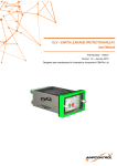
Shock Investigation Test Equipment - User Guide (Version 3) Electric Shock Investigation Test Equipment - User Guide 1. Introduction The shock investigation test equipment, manufactured by C I C, is used in the investigation of electric shock incidents or to establish if reinforced/double insulated equipment is suitable for use. Please read this user guide before using instruments and follow all safety instructions and warnings. 2. Safety Warnings The following safety warnings must be read and understood before the equipment is used and complied with during use: A hazard and risk assessment process must be carried out before use and risks adequately controlled or work should not continue. Circuit connections and exposed metalwork must not be touched during testing. Safe working procedures and practices must be followed. Precautions such as insulated gloves are to be utilised during testing. The instruments are not to be used if damaged in any way and should be destroyed and disposed of if damaged. Test leads must be in good working order and inspected before and after use. Fused test leads should be utilised. Hands are to remain behind guards of probes, clips or plugs. The equipment is to be used by suitably trained and competent persons only. 3. Symbols Caution, risk of danger: refer to the safety requirements of this user guide. Caution risk of electric shock. Reinforced insulation. 4. Equipment Use The following provides a brief summary of the purpose of the equipment. Please refer to AS/NZS60990 for more detailed explanation of the filters. AS/NZS60479, AS/NZS3760 and numerous equipment standards will provide detail of the acceptability or otherwise of test results. 4.1 Low Impedance Network – 50kΩ (Black – Red Sockets) High impedance multimeters measure the “initial” shock voltage. This voltage is likely to reduce once contact is made through the human body. This Low Impedance Network allows the operator to measure the sustained voltage at 50kΩ. If this measured voltage is less than 50 volts then CIC filters No. 4 and No. 5 can be used as they have been designed to a maximum voltage of 50 volts. The voltage measured has no relation to the “sustained” voltage a person is likely to receive, as a person’s total body impedance is much lower than 50kΩ. 4.2 Unweighted Touch Current Filter No 3 - Large Area Contact (Black – Blue Sockets) This filter is used to measure touch currents that are likely to flow through the human body where the shock voltage is less than 300 volts and where contact has been made with a large area (as per AS60479.1). It is likely to be used for electrocutions or severe injuries. This filter will provide an over estimation of the likely touch current for smaller contact area shocks. This filter is designed to AS/NZS 60990:2002 and is for INTERMITTENT USE ONLY. 4.3 Perception/Reaction Touch Current Filter No 4 (Black – Yellow Sockets) This filter is used to measure touch currents that are likely to flow through the human body where perception/reaction are the dominant consideration i.e. for “tingles”. This filter is designed for use for sustained voltages of less than 50 Volts. The low impedance network must be used to establish if the sustained voltage is less than 50 volts so this instrument can be used. This filter is designed to AS/NZS 60990:2002. 4.4 Let-go Touch Current Filter No 5 (Black – Blue sockets) This filter is used to measure touch currents where let-go is the dominant consideration i.e. the person has “locked on”. This filter is designed for use for sustained voltages of less than 50 Volts. The low impedance network must be used to establish if the sustained voltage is less than 50 volts so this instrument can be used. This filter is designed to AS/NZS 60990:2002. Manufactured by C I C Ph 02 4268 3571 Shock Investigation Test Equipment - User Guide (Version 3) 5. Low Impedance Network and Filter Operating Instructions (a) A high impedance voltmeter or multimeter (>1MΩ) on the voltage range is to be used for all measurements. The meter must also be suitably accurate. (b) Measurements are to be taken observing safety warnings/precautions and following safety working procedures and practices. (c) The meter is to be turned on and placed on the required voltage range for the particular test being carried out. (d) The “initial” shock voltage is measured by using the high impedance meter on its own to measure across the shock path. (e) The “sustained” shock voltage at 50kΩ is measured by placing the Low Impedance Network into the meter, test leads plugged into the Network and measurements taken across the shock path. (f) The likely touch current is then measured using one of the Filters plugged into the meter. Select the filter using the following reasoning: Filter No 3 is used where the “sustained” shock voltage is over 50 volts, typically where there has been an electrocution, severe injury or a large shock. Filter No 4 is used to measure “tingles” or to check reinforced or double insulated equipment is safe to use. The maximum touch current for reinforced or double insulated appliance should be measured by using the socket outlet earth as the second contact point. Filter No 5 is used to measure shock voltages where the “sustained” shock voltage is under 50 volts and the person has “locked on”. (g) The likely touch current is determined by using Ohm’s Law i.e. dividing the voltage measured by any of the three filters by 500Ω. The result of this calculation is best expressed in milliamps i.e. multiply the answer in amps by 1,000 to convert to milliamps. Alternatively, the voltage could be measured in millivolts and this value, when divided by 500Ω will give a result that is in milliamps. 6. Metal Test Plate Operating Instructions Test plates are used to simulate contact with surfaces such as concrete or the ground. The 200x100 plate is to be used to simulate the contact of both feet and the 100x100 plates are for hand or foot contact. The plate(s) should be placed on or against the shock point(s) and pressure exerted or weight applied to the plate(s) similar to the pressure or weight of the contact for the shock incident. The lead of the measuring instrument should be attached to the screw on the plate or a test probe held onto the surface of the plate. The other meter probe should be attached to the other contact point. The plates should not be used if they become corroded. 7. Instrument Operation Check The instruments may be check for operation as follows: Instrument Low Impedance Network Filter 3 Test 1* Plug the Network into the multimeter. Turn the meter onto the resistance range. The meter should read 50kΩ. Plug the filter into the multimeter. Turn the meter onto the resistance range. The meter should read 500Ω. Filter 4 Plug the filter into the multimeter. Turn the meter onto the resistance range. The meter should read 10.5kΩ. Filter 5 Plug the filter into the multimeter. Turn the meter onto the resistance range. The meter should read 10.5Ω. * Some minor variations can be expected in the test results. Test 2* Leave the Network plugged into the meter on the resistance range and connect test leads into the Network. Short the leads and the meter should read 0Ω. Leave the filter plugged into the meter on the resistance range and plug test leads into the filter. Short the leads and the meter should read 375Ω. Leave the filter plugged into the meter on the resistance range and plug test leads into the filter. Short the leads and the meter should read 10.37kΩ. Leave the filter plugged into the meter on the resistance range and plug test leads into the filter. Short the leads and the meter should read 10.37kΩ. 8. Storage Instruments must be stored appropriately to prevent damage and contamination of the banana plugs and sockets. Plates are to be stored to prevent corrosion. Manufactured by C I C Ph 02 4268 3571 Shock Investigation Test Equipment - User Guide (Version 3) 9. Trouble shooting Problem Cause The lack of readings when using the low impedance network or the filters. (The meter should read some small voltage even for a relatively low energy, induced voltage.) Dirty plugs or sockets. Solution a) Banana plugs and sockets can be cleaned using a cotton bud. b) Appropriate storage is recommended to prevent the plugs and sockets from becoming dirty. c) Test the instruments as detailed at Section 7 to ensure correct operation. 10. Repair and Maintenance The test units detailed in this user guide are not serviceable and will need to be removed from service if damaged or become inaccurate. The test units may be cleaned using warm water and should not be used until dry. Metal test plates shall be cleaned if they start to corrode. 11. Technical Specification Input Voltage Unweighted Touch Current Filter No 3 Large Area Contact 0-300V Perception/Reaction Touch Current Filter No 4 0-50V Let-go Touch Current Filter No 5 0-50V Input Frequency Power 0-50Hz 45 Watts 0-50Hz 1.25 Watts Accuracy Battery +/- 5% Nil Approx. Size Specification Item Low Impedance Network – 50kΩ Metal Test Plates 0-300V N/A 0-50Hz 1.25 Watts 0-50Hz 1.8 Watts N/A N/A +/- 5% Nil +/- 5% Nil +/- 5% Nil N/A N/A 45x30x35mm 40x30x15mm 40x30x15mm 40x30x15mm Approx. Weight 80g 30g 30g 30g Accessories Nil Nil Nil Nil 4mm Banana Sockets 4mm Banana Sockets Pressure/weight against plate to simulate shock contact 4mm Banana Shrouded Plugs Screw for alligator clamp. Input Connections 4mm Banana Sockets 4mm Banana Sockets Output Connections 4mm Banana Shrouded Plugs 4mm Banana Shrouded Plugs Protection IP64 IP64 Design Standard AS/NZS 60990:2002 AS/NZS 60990:2002 4mm Banana Shrouded Plugs IP64 AS/NZS 60990:2002 Designed to AS/NZS61010.1:2003 as far as practicable 200x100x3mm; 100x100x3mm 495g; 250g Nil IP64 N/A N/A Draft IEC 61201 N/A N/A 12. Manufacturer Manufactured in Australia by Communication Interference Consultants (CIC) 61 High Street (PO Box 509) Thirroul NSW 2515 Telephone: 02 4268 3571 Fax: 02 4268 3042 Mobile: 0429 368 775 Manufactured by C I C Ph 02 4268 3571


