1
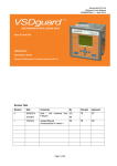
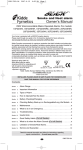
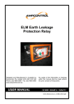
ELV – EARTH LEAKAGE PROTECTION RELAY User Manual Part Number: 170447 Version: 1.0 – January 2015 Designed and manufactured in Australia by Ampcontrol CSM Pty Ltd Ampcontrol CSM Pty Ltd – ABN 35 000 770 141 MAG-153 ELV User Manual Version 1.0 – 01/15 WARNING! CAUTION! This safety alert symbol identifies important safety messages in this manual and indicates a potential risk of injury or even death to personnel. When you see this symbol, be alert, your safety is involved, carefully read the message that follows, and inform other operators. This safety alert symbol identifies important information to be read in order to ensure the correct sequence of work and to avoid damage or even destruction of the equipment, and reduce any potential risk of injury or death to personnel. Supplementary information not directly affecting safety or damage to equipment. Carefully read the message that follows, and inform other relevant personnel. Information concerning possible impact on the environment and actions required for prevention and proper response. MAG-153 13/03/2015 10:40 Page 2 of 30 Ampcontrol CSM Pty Ltd – ABN 35 000 770 141 MAG-153 ELV User Manual Version 1.0 – 01/15 Copyright Notice The Ampcontrol ELV described in this document is the property of AMPCONTROL PTY LTD. It is furnished under a license agreement and is to be used only in accordance with the terms of the agreement. No part of the hardware or documentation may be reproduced, transmitted, transcribed, stored in a retrieval system, or translated into any language or computer language, in any form or by any means, without prior written permission of AMPCONTROL PTY LTD. Disclaimer While every effort has been made to assure the accuracy and clarity of this document, AMPCONTROL PTY LTD assumes no liability resulting from any omissions in this document, or from misuse of the information obtained herein. The information in this document has been carefully checked and is believed to be entirely reliable with all of the necessary information included. AMPCONTROL PTY LTD reserves the right to make changes to any products described herein to improve reliability, function, or design, and reserves the right to revise this document and make changes from time to time in content hereof with no obligation to notify any persons of revisions or changes. AMPCONTROL PTY LTD does not assume any liability arising out of the application or any use of any product or circuit described herein; neither does it convey license under its patent rights or the rights of others. Before You Begin We would like to take a moment to thank you for purchasing the Ampcontrol ELV Earth Leakage Relay. WARNING! To become completely familiar with this equipment and to ensure correct operation, we strongly recommend that you take the time to read and thoroughly understand this user manual. Ampcontrol Contact Details 7 Billbrooke Close, Cameron Park, NSW, 2285 P +61 1300 267 373 | F +61 2 4903 4888 EMAIL: [email protected] WEB: www.ampcontrolgroup.com MAG-153 13/03/2015 10:40 Page 3 of 30 Ampcontrol CSM Pty Ltd – ABN 35 000 770 141 MAG-153 ELV User Manual Version 1.0 – 01/15 TABLE OF CONTENTS 1 SAFETY AND OTHER WARNINGS ..................................................................5 1.1 Safe Use of Equipment ..............................................................................5 2 RECEIVING AND STORAGE ............................................................................6 2.1 Receiving ...................................................................................................6 2.2 Inspection ..................................................................................................6 2.3 Storage after Delivery ................................................................................6 2.4 Unpacking of Equipment ............................................................................6 3 INSTALLATION .................................................................................................7 3.1 General Warnings ......................................................................................7 3.2 Mandatory Installation Practices ................................................................7 4 OVERVIEW OF EARTH LEAKAGE PROTECTION ..........................................9 4.1 Overview of Protection Problems ............................................................. 10 4.2 Earth Leakage Systems ........................................................................... 11 4.3 Earth Leakage Protection and Variable Speed Drives.............................. 11 4.4 Methods of Earth Leakage Protection ...................................................... 13 4.5 Earth Leakage Toroids............................................................................. 14 5 COMMISSIONING AND CALIBRATION ......................................................... 16 5.1 Earth Leakage Test ................................................................................. 16 6 ELV OPERATION AND TESTING ................................................................... 17 6.1 Methods of Earth Leakage Protection ...................................................... 17 6.2 Mechanical Arrangement ......................................................................... 18 6.3 Electrical Connections ............................................................................. 19 7 OPERATION SUMMARY ................................................................................ 21 7.1 Rotary Switches Configuration ................................................................. 21 7.2 Indication LEDs........................................................................................ 21 7.3 Mode of Operation ................................................................................... 22 8 SERVICE, MAINTENANCE & DISPOSAL ....................................................... 23 8.1 Equipment Service ................................................................................... 23 8.2 Equipment Maintenance .......................................................................... 23 8.3 Disposal ................................................................................................... 24 9 SPECIFICATIONS .......................................................................................... 25 10 EQUIPMENT LIST ........................................................................................ 26 APPENDIX A – THE REQUIREMENT OF WEIGHTED WIDEBAND MODE ...... 27 MAG-153 13/03/2015 10:40 Page 4 of 30 Ampcontrol CSM Pty Ltd – ABN 35 000 770 141 MAG-153 ELV User Manual Version 1.0 – 01/15 1 SAFETY AND OTHER WARNINGS For safety reasons, the ELV must be installed, operated and serviced only by competent personnel. Read and understand this instruction manual completely before installing, operating or servicing this equipment. Failure to install or operate this instrument in accordance with the instructions contained in this manual may create hazardous operating conditions. 1.1 Safe Use of Equipment The equipment supplied has been manufactured according to the state of the art, and designed to ensure a safe operation. The equipment may only be used within the design parameters. The instructions within this manual must be observed as an aid towards achieving maximum safety during operation. The owner/user is responsible for observing the following instructions: 1.1.1 Changes to Equipment Changes in the design and modifications to the equipment are not permitted. Unauthorised changes made to the hardware or operating firmware will void the manufacturer's warranty, and may compromise the integrity of the system into which it is installed and other connected equipment. 1.1.2 Equipment Knowledge Experience with, or understanding of, this equipment is essential for the safe installation and removal of the equipment. Therefore, in case of a question on how to safely proceed, contact Ampcontrol immediately. 1.1.3 Manual Handling Precautions have been taken to ensure all equipment is safe to handle and free from sharp edges. However care should always be taken when handling enclosures and gloves should be worn. 1.1.4 Installation Correct operation and safety depend on the ELV and associated equipment being installed correctly. Mechanical and or electrical installation and maintenance of plant and equipment must only be carried out by appropriately qualified personnel and must be tested thoroughly prior to operation. 1.1.5 Operation As safety depends on the ELV functioning correctly it is highly recommended that all safety functions of the ELV be periodically tested to ensure correct operation. MAG-153 13/03/2015 10:40 Page 5 of 30 Ampcontrol CSM Pty Ltd – ABN 35 000 770 141 MAG-153 ELV User Manual Version 1.0 – 01/15 2 RECEIVING AND STORAGE 2.1 Receiving All possible precautions are taken to protect the equipment against damage or losses during shipment, however before accepting delivery, check all items against the packing list or bill of loading. If there are shortages or evidence of physical damage, notify Ampcontrol immediately. Notify Ampcontrol within 7 days (maximum) in case of shortages or discrepancies, according to the packing list. This action will help ensure a speedy resolution to any perceived problems. Keep a record of all claims and correspondence. Photographs are recommended. Where practicable do not remove protective covers prior to installation unless there are indications of damage. Boxes opened for inspection and inventory should be carefully repacked to ensure protection of the contents or else the parts should be packaged and stored in a safe place. Examine all packing boxes, wrappings and covers for items attached to them, especially if the wrappings are to be discarded. 2.2 Inspection Equipment that is found to be damaged or has been modified away from its published specification must not be used. Please contact Ampcontrol if the equipment is suspected to be different than that ordered or if it does not match the published specifications. 2.3 Storage after Delivery When the equipment is not to be installed immediately, proper storage is important to ensure protection of equipment and validity of warranty. All equipment should be stored indoors, preferably on shelves and protected from the elements. 2.4 Unpacking of Equipment The method of packing used will depend on the size and quantity of the equipment. The following cautions should be interpreted as appropriate. CAUTION! Take care when unpacking crates as the contents may have shifted during transport. The disposal of packaging materials, replaced parts, or components must comply with environmental restrictions without polluting the soil, air or water. Ensure that any timber and cardboard used as packaging is disposed of in a safe and environmentally responsible manner. Where possible, dispose of all waste products i.e. oils, metals, plastic and rubber products by using an approved recycling service centre. MAG-153 13/03/2015 10:40 Page 6 of 30 Ampcontrol CSM Pty Ltd – ABN 35 000 770 141 MAG-153 ELV User Manual Version 1.0 – 01/15 3 INSTALLATION 3.1 General Warnings These instructions have been designed to assist users of the ELV relay with installation. Before the ELV can be installed, there are a number of things that need to be considered and understood to prevent incorrect or unsafe operation of the ELV or the system into which it is installed. Along with relevant competence, and an understanding of the target application, the following points should be considered: 3.1.1 Ensure that the information provided in this user manual is fully understood. It is extremely important that the limitations and functionality of the ELV are understood to prevent incorrect installation and use from creating a potentially dangerous risk. If in doubt as to the nature of the limitations or their implication, consult a competent authority such as a supervisor or Ampcontrol technical representative. 3.1.2 Ensure that the application into which the relay is being installed has been properly defined, designed and approved. Any system intended to mitigate the risk of injury needs to be properly designed and implemented. Such a system must be the result of structured risk analysis with the outcomes used to define the system requirements. These requirements, in turn, will guide the choice of instrumentation, logic solvers and actuators needed to implement the system. Understanding the needs of the system will ensure proper selection of equipment. 3.1.3 Ensure that the ELV relay will properly perform the required functions within the system design. It is important to understand how the relay is intended to interact with other equipment within a system. For safe and reliable use, it is crucial that neither the ELV’s logical operation nor its signalling be compromised by incompatibilities with connected equipment. 3.1.4 Modifications of any form to the relay are prohibited. The ELV as supplied has been designed and manufactured to comply with the requirements of protection standards. If modifications of any form are made to the relay, the equipment may no longer be fit for use. If any modifications or damage to the relay is evident, do not use the equipment and contact Ampcontrol for advice. 3.2 Mandatory Installation Practices The following information must be adhered to when installing the ELV. Failure to adhere to this information may give rise to unsafe operation. Using the ELV in a manner that exceeds its electrical, functional or physical specifications, or in a way that is contrary to its operating restrictions, may create risks to personnel and/or equipment resulting in injury or death. The relay must be powered within the specified voltage range. The voltage and current ratings of the relay’s output contacts must be observed. The 4-20mA Output Signal circuit must adhere to the parameters stated in the specifications The installation of the relay must be carried out by suitably trained and qualified personnel. Identification labels fixed to the relay must not be damaged, removed or covered before, during or after installation. The installation is to be in accordance with the relevant installation Standards/Codes of Practice. MAG-153 13/03/2015 10:40 Page 7 of 30 Ampcontrol CSM Pty Ltd – ABN 35 000 770 141 MAG-153 ELV User Manual Version 1.0 – 01/15 Modifications must not be made to any part of the relay. As supplied, the unit is built to, and complies with the relevant standards. Modifications to its construction will render the unit noncompliant. Complete and accurate records of the installation must be kept as part of the site installation. MAG-153 13/03/2015 10:40 Page 8 of 30 Ampcontrol CSM Pty Ltd – ABN 35 000 770 141 MAG-153 ELV User Manual Version 1.0 – 01/15 4 OVERVIEW OF EARTH LEAKAGE PROTECTION Earthing of electrical equipment, associated machinery and structures is a seemingly simple practice and is covered adequately by the various applicable sections of Australian Standards AS/NZS 3000 or AS/NZS 3007. However, in the mining industry earthing is somewhat more complex than normal domestic or commercial applications and requires other factors to be taken into consideration, particularly where trailing and/or reeling cables supply mobile electrical equipment. The protection scheme that covers mobile and relocatable equipment used in mining and quarry operations is detailed in AS/NZS4871:2012, while the operating parameters for relays suitable for use in that distribution system are defined in AS/NZS2081:2011. Earth leakage function (as performed by the ELV) is one of six separate functions that comprise an AS/NZS4871 distribution system protection scheme (EL, EC, EFLO, LOV/CF, NER, and NERM). A best practice protection scheme for an earth fault limited network is reliant on the interaction and operation of all six devices. Omitting a complementary device from the recommended scheme requires the protection system to be assessed by a competent person or authority. The AS/NZS 4871 and AS/NZS 2081 standards are not independent. In conjunction with each other, these standards have been development in coordination with: AS/NZS 3000 – Electrical installations (known as the Australian/New Zealand Wiring Rules) AS/NZS 1802, AS/NZS 1300 - Reticulation, trailing and reeling cables. AS/NZS 1299, AS/NZS 1300 - Plugs, adaptors, couplers and receptacles. AS/NZS 2067 – Substations and High Voltage Installations Exceeding 1kV A.C. AS/NZS 3007 – Electrical Equipment in Mines and Quarries - Surface Installations and Associated Processing Plant. AS/NZS 4871 – Electrical Equipment for Mines and Quarries. Internationally accepted voltage/time effects on the human body based on IEC60479.1 and IEC60479.2. Instructions for installation in accordance with accepted State and Federal Regulations. Equipment maintained in accordance with industry standards. Earth fault protection systems designed for personnel protection must either limit the continuous touch potential to less than the extra low voltage limit (50VAC as per AS3000), or in applications where a higher touch voltages are generated under fault conditions have a total fault clearance time such that the probability of fibrillation is below an acceptable threshold. There are a number of standards that relate the maximum duration of human exposure to prospective touch voltages that do not usually result in harmful physiological effects on any person subjected to that touch voltage (i.e. ‘an acceptable limit’). Figure 1 is extracted from AS/NZS4871.1:2012 and the same figure also appears in AS/NZS3000:2007. This figure shows two curves: L – for normal conditions LP – for wet conditions Operating regions to the left of the designated curves are assumed to represent an ‘acceptable’ risk of fibrillation, although they are not necessarily as low as reasonably achievable in all instances. Operating regions to the right of the designated curves are assumed to represent an ‘unacceptable’ risk of fibrillation, even though they may be as low as reasonably achievable in some instances. MAG-153 13/03/2015 10:40 Page 9 of 30 Ampcontrol CSM Pty Ltd – ABN 35 000 770 141 MAG-153 ELV User Manual Version 1.0 – 01/15 Figure 1: Maximum Duration of Prospective 50Hz Touch Voltage (Source: AS/NZS 4871:2012) It is generally assumed that the LP curve (for wet conditions) is most applicable in coal mining applications, however the end user of the ELV must select the appropriate fibrillation curve set and commensurate clearance time for the generated touch potential given the environmental conditions of their specific application. The ELV is able to accommodate clearance times for fibrillation curve sets given in AS/NZS3000, AS/NZS4871.1:2012, AS/NZS2067:2008, and AS/NZS3007:2004 and the majority of international standards. 4.1 Overview of Protection Problems Unless properly controlled the occurrence of an earth fault can be hazardous because it may cause: Frame to earth voltages dangerous to personnel. Electric arcing, which may initiate an explosion or fire when arcing occurs in an underground mining operation. CAUTION! The main purpose of earth fault protection is to safeguard personnel and electrical apparatus. However it is found that relays designed to operate on fault limited systems are not suitable for direct contact protection, i.e. users of portable drills, grinders etc, which require trip levels of 20-30mA, with instantaneous operation. (Refer AS/NZS 3190). The most common apparatus faults in mining applications are cable faults. Cables are most susceptible MAG-153 13/03/2015 10:40 Page 10 of 30 Ampcontrol CSM Pty Ltd – ABN 35 000 770 141 MAG-153 ELV User Manual Version 1.0 – 01/15 to damage and are the major source of dangerous electrical incidents. This applies particularly to the flexible trailing cables supplying power to mobile mining machines. Cable construction is such as to provide every phase conductor with an individual conductor screen so that crushing would cause a low single phase to earth fault current. The protective device, such as an Ampcontrol ELV earth leakage relay, would then isolate the cable and contain the sparking within the cable before a heavy short circuit current due to a phase to phase fault occurs. Earth fault protection has been applied with considerable success in limiting faults and providing quick disconnection of electrical apparatus from the supply in the event of earth fault situations. A definite time operating characteristic is provided with adjustable trip sensitivity and time delay. Time delay between protective units is introduced to allow the unit close to the fault to isolate the faulty circuit without causing the healthy part of the system to be de-energised, hence providing discrimination. 4.2 Earth Leakage Systems Desirable though it may be it is impractical to provide automatic protection against electrocution as a result of direct contact with a live conductor, particularly where the electrical reticulation is exposed to a humid or damp atmosphere. The table below (taken from IEC Standards) indicates the current values affecting human beings. Current mA 1 or less 1 to 8 8 to 15 15 to 20 20 to 50 50 to 100 (possible) 100 to 200 (certain) 200 and over Symptom Causes no sensation - not felt Sensation of shock, not painful, individual can let go at will, as muscular control is not lost Painful shock, individual can let go at will, as muscular control is not lost Painful shock, muscular control of adjacent muscles lost, cannot let go Painful, severe muscular contractions, breathing difficult Ventricular fibrillation (a heart condition that may result in death) Severe burns, severe muscular contractions; so severe that chest muscles clamp the heart and stop it for the duration of the shock (this prevents ventricular fibrillation). It can be seen from the previous table that the passage of a current of as low as 15mA through the human body can cause loss of muscular control to the extent of preventing the recipient from disengaging from the live conductor. Whereas a current in excess of 50mA is sufficient to produce a critical heart condition from which there is little or no chance of recovery. It follows that as an effective safeguard against electrocution resulting from direct contact with a live conductor, it would be necessary to introduce earth leakage protection designed to operate with a fault current below 15mA, which in the majority of cases, would be impractical. The automatic protection of circuits is not intended to take the place of sound installation practice and the regular maintenance and testing of electrical apparatus, so as to avoid direct contact scenarios. Care must be taken in the selection and installation of all electrical equipment with due regard to its required duty and the conditions under which it may be called upon to operate. Where automatic earth leakage protection has been installed it is essential that its operation be tested often, and to facilitate this, a means for testing is incorporated in all approved earth leakage relays. 4.3 Earth Leakage Protection and Variable Speed Drives Earth Leakage protection systems were originally devised to protect against touch potential hazards caused by earth fault currents driven by the power supply (50Hz). Consider, for example, that an earth fault occurs in a mobile machine powered by a trailing cable. The earth fault current will flow through the MAG-153 13/03/2015 10:40 Page 11 of 30 Ampcontrol CSM Pty Ltd – ABN 35 000 770 141 MAG-153 ELV User Manual Version 1.0 – 01/15 fault to the machine frame and return to the supply transformer star point via the trailing cable earth conductors. The voltage drop caused will result in a potential rise above earth on the frame, presenting a touch potential hazard. As described in AS/NZS 4871.1:2012 the system assessment must determine the earth fault limitation current that will protect people based on the achievable earth leakage clearance times and knowledge of the system in which it is installed. 4.3.1 Variable speed drives Variable speed drives (VSDs) are now finding wide use in mining applications. Most of these drives use variable frequency outputs that are produced by rectifying the supply to DC and then inverting this voltage back into AC using a high frequency carrier and pulse width modulation (PWM) to produce variable frequency currents in the motor. They complicate the situation in several ways: 1) VSDs introduce a new and complex voltage source into the power system. This may mean that earth faults can now be direct current (DC) in nature, or may be driven by the inverter of the drive and so have a frequency that is primarily that of the drive PWM carrier frequency (1000Hz for example). 2) To minimise interference with protection and control systems, many drives employ electromagnetic compatibility (EMC or EMI) filters that consist primarily of a capacitive circuit between the input of the drive and earth. This provides a path for the earth currents that represents an alternative path to the NER, as shown in Figure 2 below. In fact, it is the intention of the filter to provide this alternative path for the high frequency currents that flow (through the motor and cable stray capacitances) to earth under normal conditions. They will also provide an alternative path under fault conditions, particularly if the fault is driven by the high switching frequency drive output. It has also been shown that when one or more drives and filters are in use, and an earth fault occurs, there can be circulating currents between the drives and filters and/or the fault location. The fault current magnitudes may then greatly exceed the nominal current limitation value (typically 5A) determined by the NER. These large currents may cause touch potentials that greatly exceed the expected values. 3) Most earth leakage protection relays approved for use in mining applications are designed to detect 50Hz currents, not DC or high frequency currents so that the relays may not trip, or if they do trip they may take longer than expected. Figure 2: Alternative Earth Current Paths The overall result is that with standard earth leakage protection relays and electrical system assessments based only on consideration of faults driven by the supply system (50Hz), protection performance is unlikely to be adequate when variable speed drives are used in mining applications MAG-153 13/03/2015 10:40 Page 12 of 30 Ampcontrol CSM Pty Ltd – ABN 35 000 770 141 MAG-153 ELV User Manual Version 1.0 – 01/15 4.3.2 Improving protection The design of earth leakage relays used in mining applications in Australia and New Zealand must comply with AS/NZS 2081. The latest version of this standard (AS/NZS 2081:2011) better recognises that system protection needs to be assessed in accordance with AS/NZ 4871.1:2012 and with the changes in the mining electrical environment. The following extracts from AS/NZS 2081:2011 provide some key statements of interest: 1.1 Scope: Whereas this standard is based upon 50Hz supply systems, it is envisaged that the equipment described may also be installed in systems with higher, lower or variable frequencies, or in DC supplied systems. AS/NZS 60479, Part 1 and 2 should be referenced for consideration of the effects of current at other supply frequencies upon the human body. Appendix B: The diversity of operating conditions and equipment addressed by this Standard precludes reliance solely on explicitly prescribed trip levels or fault current levels, and their duration, in order to ensure a safe working environment. Rather, the onus is placed on the system designer to ensure appropriate touch voltage/operating times when integrating the protection devices addressed by this Standard. B2 Voltage/duration Thresholds Design criteria for the protection devices have been chosen to enable compliance to the touch voltage/operating times for systems operating at 50 Hz as described by Figure B1. B3 Systems at other than 50Hz Cyclic Frequency Where equipment is installed and operated within systems at other than a constant 50 Hz cyclic frequency, the characteristics in paragraph B2 are not immediately applicable. In such instances, individual calculation to determine requirements at the frequency or frequencies in question will be required. Standards AS/NZS 60479.1 and AS/NZS 60479.2 should be referenced in relation to the effects upon the human body of other supply frequencies. What this means is that when VSDs (or other non 50Hz sources) are used in a mining electrical system then the standard approach needs to be interpreted to ensure that protection is adequate. The key factors to consider are as follows: 1) The sensitivity of the human body to electric shock varies with frequency. In general, for a given exposure time, the allowable touch voltage magnitude increases with frequency. For example, at 10kHz, the “let go” voltage is about 5 times the level at 50Hz. 2) When EMC filters are used, this forms a path for earth currents alternative to the NER. When considering touch potentials at a mobile machine for example, strictly speaking the impedance of the filter at the frequency of interest should be examined in order to determine the earth fault current that will flow when a fault occurs in the machine. The earth leakage trip time must then be used to ensure that the touch voltage and exposure time guarantee a safe system. Care must be taken when multiple filters are connected to a single supply, as this presents many modes of possible earth fault that need to be considered and actual earth fault currents may exceed the current seen by any single filter. 3) An earth leakage relay must be able to accurately sense earth fault currents of any frequency from DC to the maximum frequency of interest. 4.4 Methods of Earth Leakage Protection Earth Leakage Protection Relays for use in mining applications have to be designed and tested to MAG-153 13/03/2015 10:40 Page 13 of 30 Ampcontrol CSM Pty Ltd – ABN 35 000 770 141 MAG-153 ELV User Manual Version 1.0 – 01/15 AS/NZS 2081:2011 for use on fault limited systems. There are two methods of protection used, Core Balance and Series Neutral earth leakage protection systems. A relay installed in Core Balance applications performs the primary protection in an installation, protecting the outlet supplying power to a machine. In this application the time delay is set at instantaneous. Series Neutral earth leakage provides backup protection for the installation and can have a time delay up to a maximum of 500ms. 4.4.1 Core Balance Protection With this method all three phases of the cable are passed symmetrically through the toroid. If there is no earth fault present, the vector sum of the currents in a three-phase supply is zero. If current from any phase flows to earth the toroid flux becomes unbalanced. The toroid produces an output, which trips the relay. A test current is injected through the window of the toroid to test the operation of the relay. 4.4.2 Series Neutral Protection With this method the neutral is passed through the toroid. An earth fault on any of the phase conductors causes an earth current which returns, through the toroid, to the star point of the transformer. A test circuit can connect a test resistor between a phase and earth or inject a current through the toroid as previously described. The test resistor to earth method is recommended with this type of protection as this test also proves the neutral to earth connection. 4.5 Earth Leakage Toroids Toroids (current transformers) are not ideal devices and if correct procedures are not followed during installation, nuisance tripping can result. If, for example, we consider a single-phase earth leakage system where active and neutral pass through a toroid then at all times currents in the two wires are equal and opposite so that the net current through the toroid is zero. An ideal current transformer would have all of the flux from each wire contained in the core and so would accurately add the opposing fluxes to get a net result of zero. A real current transformer has “leakage fluxes”. This means that a very small proportion of the total flux from each cable is not contained in the core but in the space outside it and as a result it may link some turns but not others, depending on the positioning of the cables. The effect of this is that a small output may be obtained from the toroid where none would arise if the device were ideal. The size of the error may vary from toroids of the same type because of slight differences in the core and the symmetry of the winding. Problems caused in this way increase as the toroid size increases, as currents increase and symmetry decreases. Nuisance tripping tends to occur when the total current rises, such as when a large motor is started. The following guidelines may help to avoid such problems. 4.5.1 Toroid Selection i. Select the smallest internal diameter toroid, which will allow the cables to fit through. Avoid very large toroids (200mm) or toroids with square apertures. ii. The ELV has been designed for use with the Ampcontrol EL500S series of toroids. For ordering part numbers, refer to the Equipment List in Section 10. iii. Only use approved toroids specified by Ampcontrol as these have been designed for optimum performance. CAUTION! MAG-153 The ability of the ELV relay to detect high frequency earth leakage currents (up to 10kHz) is dependent upon the installed toroid’s performance and reflection coefficient. Only the Ampcontrol EL500S series of Toroids is to be used with the ELV. 13/03/2015 10:40 Page 14 of 30 Ampcontrol CSM Pty Ltd – ABN 35 000 770 141 MAG-153 ELV User Manual Version 1.0 – 01/15 4.5.2 Toroid Installation Guidelines i. Keep cables as close to the centre of the toroid as possible. Do not tie them to one side of the toroid as this will reduce symmetry. ii. Do not bring the cables back within a diameter distance of the toroid. This will reduce cable symmetry. iii. Avoid placing the toroid near to any device which produces magnetic fields, for example busbars, transformers or other cables. Where possible maintain clearances in excess of several diameters distance from the toroid. iv. Multiple small cables may present more issues than larger cables. This should be considered in circuit design. v. Busbars cannot be passed through toroids used for core balance earth leakage protection. vi. To prevent possible nuisance tripping it is suggested that the conductor screen of the earth leakage toroid be earthed at the relay end only. If both ends are earthed there is a possibility that the shield may become an earth loop, injecting noise into the toroid leads. vii. To reduce noise pickup, install twisted pair cable between the protection device and the toroid. viii. The resistance between the protection device and the toroid must be kept as low as practicable to ensure that a trip on the protection device does not occur. CAUTION! MAG-153 The ELV relay includes a circuit for continually testing the toroid connection. The resistance of the wiring between the relay and toroid must be kept below 1Ω. If this is not done then a “CT” fault will be detected and the relay will trip. 13/03/2015 10:40 Page 15 of 30 Ampcontrol CSM Pty Ltd – ABN 35 000 770 141 MAG-153 ELV User Manual Version 1.0 – 01/15 5 COMMISSIONING AND CALIBRATION Prior to being put into service, the electrical protection system must be correctly commissioned. This manual does not cover system commissioning; the full scope of commissioning tests should be determined during the risk assessment or FMEA covering the design of the electrical protection system. The following test can provide guidance on checking the correct operation of the ELV during commissioning. This is not intended to provide an exhaustive commissioning checklist, but should be considered to be a minimum set of tests. 5.1 Earth Leakage Test Inject a test current at 120% of the trip level setting through the toroid, as shown in Figure 5. Verify that the ELV relay trips as expected. MAG-153 13/03/2015 10:40 Page 16 of 30 Ampcontrol CSM Pty Ltd – ABN 35 000 770 141 MAG-153 ELV User Manual Version 1.0 – 01/15 6 ELV OPERATION AND TESTING The Ampcontrol ELV Earth Leakage Relay is electronic in design and is based on microprocessor technology. It is designed to AS/NZS 2081:2011 Section 6. The ELV uses patented technology (AU2011264414) to characterise earth leakage currents giving superior fault discrimination, particularly in applications involving switching power electronics and variable speed drives. The relay uses a toroid to measure earth fault current. A definite time operating characteristic is provided with adjustable trip sensitivity and time delay. When a fault occurs and the trip level and time delay is exceeded the relay’s trip function is activated, which operates the trip contacts connected in the system control circuit. The trip condition is latched in non-volatile memory and requires operation of the reset input to clear the trip condition. An internal reset is also provided on the fascia of the relay. A ten-segment LED bar graph indicates the percentage of leakage level being detected. This reading can be remotely monitored/displayed using the 4-20mA output of the relay. The user has the ability to switch the relay between wideband (up to 10kHz), narrowband (power frequency) and weighted frequency mode (up to 10kHz, high frequency compensated). The ELV Earth Leakage Relay is housed in a stainless steel case and can be either ‘DIN Rail’ or ‘Panel’ mounted through a 69 x 39mm cut out. When panel mounted the front of the ELV relay is designed to provide IP56 ingress protection. There is provision to prevent unauthorised adjustment of the trip settings by sealing the post (in front of the knurled nut) with a lead seal or the use of a padlocked cover (see the equipment list for part number), thus inhibiting the unauthorised removal of the front fascia cover. An internal switch mode power supply allows the ELV to operate from 24VAC to 110VAC or 24VDC to 150VDC. The ELV Relay has been designed and tested for use on fault-limited systems. To ensure maximum protection the earth leakage system should be used in conjunction with the other protection systems covered by AS/NZS 2081. The collective systems are designed to limit touch and step potentials. The relay is also suitable for industry where equipment or system earth leakage protection is required. The relay is not suitable for personal protection, which requires trip levels of 20-30mA, with instantaneous operation (refer to AS/NZS 3190). The ELV relay continually monitors the toroid and if the connection is lost the relay will trip and flash the ‘CT Fault’ LED. CAUTION! The ELV relay includes a circuit for continually testing the toroid connection. The resistance of the wiring between the relay and toroid must be kept below 1Ω. If this is not done then a CT fault will be detected and the relay will trip. 6.1 Methods of Earth Leakage Protection The ELV Relay is suitable for both core balance and series neutral methods of protection (see Section 4.4, Methods of Earth Leakage Protection, for details). MAG-153 13/03/2015 10:40 Page 17 of 30 Ampcontrol CSM Pty Ltd – ABN 35 000 770 141 MAG-153 ELV User Manual Version 1.0 – 01/15 6.2 Mechanical Arrangement 6.2.1 Enclosure The ELV is housed in a plastic and stainless steel enclosure and is rated as IP20. The ELV enclosure is designed to be either DIN rail or Panel mounted. The dimensions are shown in Figure 3 below: Figure 3: ELV enclosure dimensions – Panel mounted (top) and DIN rail mounted (bottom) 6.2.2 Front Panel The front fascia of the ELV relay consists of a two switches for selection of the Trip Level and Trip Time, five (5) indication LEDs for diagnostics support and a ten-segment LED bar graph to display the level of Earth Leakage current being measured. Figure 4Figure 5 shows the front fascia of the relay. Figure 4: ELV Front Fascia MAG-153 13/03/2015 10:40 Page 18 of 30 Ampcontrol CSM Pty Ltd – ABN 35 000 770 141 MAG-153 ELV User Manual Version 1.0 – 01/15 6.3 Electrical Connections Once the ELV relay has been mounted in a suitable location, it is necessary to wire it correctly. Figure 5 shows a typical wiring diagram for the application of the ELV relay. Incoming Supply Remote Monitoring Output Alternative Toroid Position Relay Contacts Shown in the De-energised State Supply Transformer 24-110Vac NC-2 10 4-20mA + Com-2 9 19 4-20mA - NO-2 8 18 Com-1 7 17 NO-1 6 16 PWR-2 5 15 PWR-1 4 Earth 3 Test Circuit CT-com 2 ELV 10-30Vdc PLC Analog Input or Remote Indication Meter Ext Reset Non Fail Safe Link (NOT USED) 14 Link-3 13 Narrowband Link-2 12 Wideband Frequency Response Selection Links Link-1 11 CT-sig 1 Toroidal Current Transformer Alternative Supply LOOP RESISTANCE <1 Ohm Load - PWR-2 24-168Vdc + PWR-1 5 4 Figure 5: ELV Typical Electrical Application 6.3.1 Supply The ELV relay is able to operate across both AC and DC voltages ranges. The supply voltage can be 24110VAC +/- 20% at 50Hz, or 24-168VDC +/- 10%. 6.3.2 Reset A tripped ELV can be reset two ways; by pressing the reset button located on the front fascia or via an external NO contact connected to the ELV terminals labelled “Ext Reset”. If an external reset is used, it is recommended that a twisted pair be used between the N/O contact and the reset input. Pressing the reset button will also display the highest earth leakage current measured since the last time the reset button was pressed. This is displayed as a slow flashing on the bar graph for 2s after the reset button is pressed. 6.3.3 Toroids The ELV relay is designed for use with Ampcontrol EL500S series 100:1 Toroids. They are available with window sizes 25, 60, & 112mm. These allow trip settings from 30mA to 2.5A. 6.3.4 Frequency Response The user has the ability to switch between three frequency response modes: Narrowband, Wideband and Weighted Wideband. These options are selected via three digital input links into the relay and MAG-153 13/03/2015 10:40 Page 19 of 30 Ampcontrol CSM Pty Ltd – ABN 35 000 770 141 MAG-153 ELV User Manual Version 1.0 – 01/15 displayed via two LEDs on the front of the ELV (labelled Wideband and Narrowband). See Section 7.3 for more information on the operation of each mode. MAG-153 13/03/2015 10:40 Page 20 of 30 Ampcontrol CSM Pty Ltd – ABN 35 000 770 141 MAG-153 ELV User Manual Version 1.0 – 01/15 7 OPERATION SUMMARY 7.1 Rotary Switches Configuration 7.1.1 Trip Level Selection The trip level can be selected via the rotary switch at the front of the unit labelled “Trip Level”. The trip level represents the threshold of current measured by the earth leakage toroid, above which a trip occurs. The trip level is selectable from 30mA to 2.5A. 7.1.2 Time Delay Selection The time delay can be selected via the rotary switch at the front of the unit labelled “Trip Time”. The trip time represents the delay after which a fault condition has occurred when the ELV relay will deenergise. Time Delay settings are selectable from 50ms to 500ms. 7.2 Indication LEDs 7.2.1 Healthy LED LED state Off On Flashing Indication Power Off; microprocessor not operating correctly ELV starting or microprocessor not operating correctly Microprocessor is correctly operating 7.2.2 Trip LED LED state Off On Flashing Indication Relay is healthy Relay has tripped due to a fault condition N/A 7.2.3 Relay LED LED state Off On Flashing Indication Relay is not energised Relay is energised N/A 7.2.4 CT Fault LED LED state Off On Flashing Indication Earth Leakage toroid connection healthy N/A Connection lost to the Earth Leakage toroid 7.2.5 Wideband and Narrowband LEDs Wideband LED Narrowband LED Off Off On Off Off On On On Flashing Flashing N/A Wideband mode selected Narrowband mode selected Weighted mode selected N/A MAG-153 13/03/2015 10:40 Page 21 of 30 Ampcontrol CSM Pty Ltd – ABN 35 000 770 141 MAG-153 ELV User Manual Version 1.0 – 01/15 7.3 Mode of Operation 7.3.1 Fail Safe Operation To comply with AS/NZS 2081:2011 the relay can only be operated in fail-safe mode. This is the only mode of operation provided (the non-fail safe link is disabled), where the relay drops out on fault or loss of power. Power to the relay must be from the line side of the isolating device or from an independent supply. 7.3.2 Narrowband Response When Narrowband is selected the ELV uses a low pass filter to prevent tripping on earth leakage currents above 50Hz. In this mode of operation the ELV behaves like a traditional earth leakage relay, such as the ELD. This mode can be activated by bridging links 1 and 2. 7.3.3 Wideband Response In Wideband mode the ELV does not utilise any frequency discrimination up to 10kHz. This mode can be activated by bridging links 2 and 3. 7.3.4 Weighted Response Utilising a patented technique (AU2011264414) weighted mode provides a scaled earth leakage response to take into account the reduced sensitivity of the human body to touch potentials at higher frequencies. This improved frequency discrimination reduces the occurrence of nuisance trips. This is the default mode and can be activated by bridging links 1 and 3. If no links are bridged the ELV will default to this mode. MAG-153 13/03/2015 10:40 Page 22 of 30 Ampcontrol CSM Pty Ltd – ABN 35 000 770 141 MAG-153 ELV User Manual Version 1.0 – 01/15 8 SERVICE, MAINTENANCE & DISPOSAL 8.1 Equipment Service The ELV relay requires no internal servicing during its normal operating life. A number of external system based checks should however be completed on a regular basis. These ‘routine inspections’ must be carried out by suitably trained people with knowledge of the relay and the systems into which it is fitted. Routine inspections may take the form of either visual-only checks, or visual and ‘hands-on’ checks. 8.1.1 Visual Only Inspections A basic visual inspection focuses on looking at the installation for signs of physical damage, water or dust ingress and the condition of cables and labels. This type of inspection may involve opening cabinets to gain access to the ELV and other equipment. This level of inspection may also include cleaning display windows that have become obscured by dirt. Observations would typically be: Check that equipment enclosures, cable trays, conduits, etc. are in good order with no physical damage. Check that sealed wall boxes are free from water and dust ingress internally. Door seals are in good condition. Check that connected cables are free from cuts, abrasions and obvious signs of damage. Cable restraints are in good order and correctly fitted. Check that labels on equipment, wall boxes and cables are present and in good condition (especially certification labels). Check that no modifications have been carried out to installed equipment. 8.1.2 Hands-On (Detailed) Inspections A more detailed inspection would include all of the elements of a visual inspection, plus some checks that cover the integrity of connections, fixtures and fittings. In addition to basic visual observations, more detailed integrity checks would involve: Verify that equipment housings, wall boxes and other mechanical fixtures are secured in place. This includes terminal box lids, tightness of cable glands, integrity of wall-box mountings, security of equipment fixing to walls/DIN rails etc. Verify all electrical connections are secure with no loose screw terminals or DIN rail terminals not fitted to rails etc. 8.1.3 Earth Leakage Test An earth leakage test should be performed at regular intervals to ensure the integrity of the earth leakage protection. Inject a test current at 120% of the trip level setting through the toroid, as shown in Figure 5. Verify that the ELV relay trips as expected. 8.2 Equipment Maintenance WARNING! MAG-153 The ELV relay has no user-serviceable parts. All repairs must be carried out by Ampcontrol only. If a fault develops, return the relay to Ampcontrol for repair. It is essential that no attempt be made to repair the relay as any attempt to dismantle or repair the relay can seriously compromise the safety of the unit. 13/03/2015 10:40 Page 23 of 30 Ampcontrol CSM Pty Ltd – ABN 35 000 770 141 MAG-153 ELV User Manual Version 1.0 – 01/15 8.3 Disposal The electronic equipment discussed in this manual must not be treated as general waste. By ensuring that this product is disposed of correctly you will be helping to prevent potentially negative consequences for the environment and human health which could otherwise be caused by incorrect waste handling of this product. MAG-153 13/03/2015 10:40 Page 24 of 30 Ampcontrol CSM Pty Ltd – ABN 35 000 770 141 MAG-153 ELV User Manual Version 1.0 – 01/15 9 SPECIFICATIONS Supply Voltage Voltage Power Consumption Operating Temperature Humidity 24-110VAC +/- 20%, 50Hz 24-168VDC +/- 10% < 3W 0 to 60°C Between 10% relative humidity and the dew point, non-condensing Operating Frequency Frequency Accuracy Relay Contacts Contacts Ratings Relay to Toroid Narrow Bandwidth 50Hz 5% @ 50Hz Weighted & Wide Bandwidth 5Hz – 10kHz 5% @ 50Hz 1 x NO / 1 x CO 250V, 1.6A, 400VA < 1Ω 4-20mA Output Loop Supply Voltage Max. Loop Resistance Accuracy The ‘Loop Powered’ current represents the leakage current as a % of the trip level. 4mA => 0% leakage, 20mA => 120% leakage (100% = 17.33mA) 10 – 30VDC 700Ω at 24V loop supply +/- 2% of full scale Mechanical Dimensions IP Rating 77x47x116mm IP56 (when panel mounted) 4-20mA Output Trip and Time Delay Settings Switch Position Trip Level mA (Accuracy +/- 5%) 0 30 1 60 2 100 3 150 4 200 5 250 6 300 7 350 8 400 9 450 A 500 B 750 C 1000 D 1500 E 2000 F 2500 MAG-153 13/03/2015 10:40 Time Delay mS (Accuracy +0ms, -20ms) <50 100 150 200 250 300 350 400 450 500 500 500 500 500 500 500 Page 25 of 30 Ampcontrol CSM Pty Ltd – ABN 35 000 770 141 MAG-153 ELV User Manual Version 1.0 – 01/15 10 EQUIPMENT LIST Part Number 170447 101399 120255 164672 115437 101658 101656 MAG-153 Description ELV Earth Leakage Relay ELD DIN Rail Mounting Kit ELD-ELC/F Adapter Kit ELD PADLOCKABLE COVER Toroid – 25mm ID Toroid – 60mm ID Toroid – 112mm ID 13/03/2015 10:40 Page 26 of 30 Ampcontrol CSM Pty Ltd – ABN 35 000 770 141 MAG-153 ELV User Manual Version 1.0 – 01/15 APPENDIX A – THE REQUIREMENT OF WEIGHTED WIDEBAND MODE A1. Earth Leakage Requirements from AS/NZS 4871 & AS/NZS 2081 The 2011 revision of AS/NZS2081 correctly recognises that system protection must be assessed in keeping with touch potential curves in AS/NZS4871:2012 but acknowledges that this curve is for 50Hz (so power frequency) only. AS/NZS2081 explicitly draws attention to the fact that 50Hz curve sets are not immediately applicable in systems that contain equipment capable of generating non-50Hz components, and that in such instances; touch potential calculations must be supported by individual calculation to determine requirements at the frequency or frequencies of interest. AS/NZS2081:2011 Clause 1.1 Scope: Whereas this standard is based upon 50Hz supply systems it is envisaged that equipment described may also be installed on systems with higher, lower or variable frequencies, or in DC supplied systems. AS/NZS60479 Part 1 and 2 should be referenced for the consideration of the effects of current at other than supply frequencies on the human body. AS/NZS2081:2011 Appendix B3 Systems at other than 50Hz Cyclic Frequency: Where equipment is installed and operated within systems at other than a constant 50Hz cyclic frequency, the characteristics in paragraph B2 are not immediately applicable. In such instances individual calculation to determine requirements at the frequency or frequencies in question will be required. Figure A1: Source – AS/NZS 2081:2011 Appendix B The vast majority of earth leakage relays approved for use in mining applications are designed to detect 50Hz currents, not DC or high frequency currents associated with a variable speed drive carrier or MAG-153 13/03/2015 10:40 Page 27 of 30 Ampcontrol CSM Pty Ltd – ABN 35 000 770 141 MAG-153 ELV User Manual Version 1.0 – 01/15 switching frequency. A number of protection relays are marketed as suitable for variable speed drive protection as they include a detection bandwidth that covers the synthesised power frequency spectrum of most VSD’s (up to 150Hz). When traditional narrowband relays (with a current detection bandwidth below a few hundred Hz) are presented with DC and/or high frequency currents, the relays may not trip, or if they do may take longer than expected. Whilst a user may have considered higher frequencies (such as the drive carrier frequency) and may have even done so via calculation, the protection system must properly resolve both frequency and magnitude of E/L current in order to trip appropriately at the frequency of interest. Observation #1: A system containing a variable speed drive cannot be assessed as compliant to AS/NZS4871 and/or AS/NZS2081 without fitment of wideband earth leakage protection. The bandwidth of installed E/L protection must extend to at least the variable speed drive carrier frequency in order to be argued as compliant. A2. Wideband Earth Leakage Protection Traditional wideband earth leakage protection relays typically have a unity characteristic as a function of frequency over their bandwidth. This arguably allows compliance against AS/NZS4871 & 2081 in that the earth leakage current spectrum is within the resolution bandwidth of the protection relay, with two important related caveats: (1) Sensitivity: Consider the case where a variable speed drive is installed but has no common mode EMC filter, or any common mode filtering installed is only small. Under normal operating circumstances there will be a circulating earth leakage current from the drive back through the NER. The presence of this current does not indicate a fault and is normal. Its primary current component is at the carrier frequency, not 50Hz or the synthesised power frequency of the drive. The value of the normal standing leakage current depends on the drive output characteristics and the parasitic capacitance of the load motor, but can be relatively high. It is common for the standing earth leakage current to be much higher than traditional E/L trip values of a few hundred milliamps, with practical mining cabling and motors it can be as much as a few amperes. It is not practical to detect small changes in E/L current (perhaps 100mA or so) in the presence of a large (a few amps) normal circulating E/L current. Invariably, trip settings close to the normal circulating current are prone to nuisance tripping and poor protection reliability. Nuisance tripping often sponsors end users to raise the trip level in an attempt to remove nuisance tripping, but this simply desensitises the protection to high impedance faults, requiring larger fault currents before the fault can be seen by the protection relay. (2) Tripping ratio: AS/NZS4871.1:2012 clause 2.6.2.2 prescribes that “The ratio of earth fault current to earth leakage protection trip should be at least 10.” This ratio can be lowered to 5 “where capacitive charging currents cause spurious tripping”. A common earth fault limitation value used widely in Australian mining operations is 5A, and the requirement for a 10:1 tripping ratio indicates the earth leakage trip level should be no more than 500mA. In all cases the fault current trip level MAG-153 13/03/2015 10:40 Page 28 of 30 Ampcontrol CSM Pty Ltd – ABN 35 000 770 141 MAG-153 ELV User Manual Version 1.0 – 01/15 should be set just above the normal steady state background earth leakage so as to be reliable without nuisance tripping. That is, the tripping ratio should be maintained as high as practical. In many practical examples involving protection of variable speed drives with wideband protection relays, tripping ratios are unable to be maintained in compliance with AS/NZS4871.1:2012, or indeed as high as would otherwise be desired. Observation #2: Tripping ratio and the requirement to maintain sensitivity of earth leakage detection as per AS/NZS4871.1:2012 is problematic when applying wideband earth leakage relays to earth fault limited electrical systems containing variable speed drives. The necessary settings for a wideband relays typically result in nuisance tripping. A3. Weighted Wideband Earth Leakage Protection The sensitivity of the human body to electric shock varies with frequency. In general, for any given exposure time, the allowable touch potential rises as frequency increases. For example, at 1kHz the allowable body current (not touch potential) is approximately 14 times higher than at 50Hz. As a consequence, it can be shown that the application of wideband earth leakage protection (discussed in the previous section) in an earth fault limited system where acceptable touch potentials are limited to magnitude and durations defined by 50Hz curve sets will be conservative. Unfortunately, this conservatism in protection settings often results in a significant degradation of system reliability through nuisance tripping and/or trade off of fault detection sensitivity. Curve sets relating the effect of frequency on likelihood of fibrillation as a function of body current are contained in AS/NZS60479 parts 1 and 2. It is important to note that these curve sets are for body current, not touch potential. It is necessary to relate these curve sets to touch potential by accounting for additional series impedance (be that clothing, human skin resistance and a number of other parameters) all of which vary as differing functions of frequency. Strictly speaking, the impedance to earth at each frequency of interest must be calculated to then determine the resultant earth fault current, and so calculate touch potential at each frequency of interest to then cumulatively apply the curve sets contained in 60479 and so determine the necessary safe clearance time. It is impractical for the user to utilise these curve sets directly in touch potential calculations. Both Ampcontrol VSDguard and ELV relays are capable of weighting the wideband E/L current as a function of frequency according to the curve sets in AS/NZS60479. This weighting accounts for the differing effects of frequency on fibrillation risk automatically, and while the actual current measurement is wideband, the weighting produces a ‘50Hz equivalent risk’ touch potential. That is, for a given earth continuity, the weighted wideband current will produce an equivalent risk wideband touch potential as the same magnitude narrowband (50Hz) current. In practice the user completes touch potential studies using the established (and familiar) 50Hz touch potential curve sets contained in AS4871, AS3007 and AS2067, ultimately choosing the parameters of earth fault limitation, earth continuity and clearance times. The E/L trip current is then set in weighted mode to a level that is just above the normal (weighted) circulating current (as would always be the methodology to set the trip level even if the system was 50Hz only). MAG-153 13/03/2015 10:40 Page 29 of 30 Ampcontrol CSM Pty Ltd – ABN 35 000 770 141 MAG-153 ELV User Manual Version 1.0 – 01/15 Observation #3: Weighted mode automatically applies the curve sets as a function of frequency in AS/NZS60479 parts 1 & 2, and so is fully compliant with AS/NZS2081:2012 for earth fault limited systems with non-50Hz connected equipment. Weighted mode minimises nuisance tripping often associated with traditional wideband earth leakage protection, by maximising the possible tripping ratio as a function of frequency. In addition, weighted mode provides increased low frequency E/L sensitivity (improving the relays ability to detect high impedance faults) as the protection system is no longer dominated by large (but normal) high frequency circulating currents typical of VSD applications on earth fault limited systems. Similarly, the protection is not simply blinded to ignore high frequency current (as would be the case if the E/L signal was simply low pass filtered), and protection properly accounts for high frequency current contribution to fibrillation risk. Ampcontrol holds an international patent (PCT/AU2011/000705) in regard to the use of frequency discrimination as applied to earth fault protection. MAG-153 13/03/2015 10:40 Page 30 of 30