1
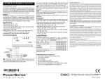
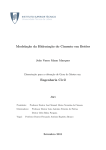
MiTE Installa on
and
User Guide
Version 1.0 — December 2013
Se ng Up MiTE
Set-up Data Acquisi on
MiTE is compa ble with any Na onal Instruments® device compa ble with NI-DAQmx™. In this guide, a Na onal Instruments
USB-6008 is used as the data acquisi on device.
Step 1
Locate NI-DAQmx™ So ware DVD
Before connec ng anything to the computer, the Na onal Instruments® NI-DAQmx™ so ware and drivers should be
installed. A copy of this so ware should be included with the data acquisi on hardware.
Step 2
Install NI-DAQmx™ So ware
2.1 Insert the DVD into the computer
1
2.2 If an AutoPlay message is shown, select
‘Run autorun.exe’ (the highlighted op on).
2.3 When the installer starts select the op on to ‘Install NI-DAQmx’
2.4 A user account control (UAC) message may be displayed. Press ‘Yes’ to con nue the installa on process.
2.5 Select the ‘Custom’ installa on op on, then press
the ‘Next’ bu on
2.6 The features shown are the minimum required by
MiTE. If required, addi onal features can be installed.
Once the features are selected press the ‘Next’ button.
2.7 If desired the check-box on this screen may be selected to search for updates during the installa on
process. This will require a connec on to the Internet. Press the ‘Next’ bu on.
2
2.8 A set of license agreements will be displayed. If
accepted, press the ‘Next’ bu on.
2.9 Another set of license agreements may be displayed. If accepted, press the ‘Next’ bu on.
2.10 An op on is available to trust so ware from Naonal Instruments®. Accep ng this op on will prevent confirma on dialogs appearing during installaon. Press the ‘Next’ bu on.
2.11 The installa on is now ready to start. A list of
changes to be made is displayed. Press the ‘Next’ button to begin installa on.
3
2.13 The installa on is now complete. Press the
‘Next’ bu on.
2.12 If a message asking to install a driver published by Na onal Instruments Corpora on is displayed press ‘Install’ to con nue the installa on
2.14 If prompted to restart, press the ‘Restart’ bu on.
4
Step 3
Connec ng the signal to the Data Acquisi on Device
Note that these instruc ons apply to the Na onal Instruments® USB-6008 device. If a different device is used the procedure may differ.
Take one of the connectors for the Na onal Instruments® USB-6008 (There should be 2 in the box). If desired, a label can
be placed on the connector to aid in connec on (the numbered label is shown below).
In this guide, this input signal will be connected to the first analogue input, named AI0. Place the ground wire into the
le -most connec on, and the signal wire into the adjacent connec on as shown below. If the analogue connector label is
used, these connec ons are labelled GND and AI0 respec vely.
Once inserted the wires can be secured in place by ghtening the screws above the connec on points.
These wires can then be connected to the load signal. Here they will be connected using a BNC adapter.
5
The connector can now be inserted into the data acquisi on device. Be sure to insert it on the side marked ‘Analog’.
Once the connector is inserted and the NI-DAQmx™ so ware has been installed, the device can be connected to the computer
through a USB port. First insert the square end of the USB cable into the device, then the rectangular end into the computer.
6
Step 4
Connec ng the camera
Depending on the type of camera used, the procedure to connect is different. For a FLIR 315, FLIR 325, or another
externally powered camera, follow procedure 4A. For a FLIR A35, or another camera powered through the Ethernet cable,
follow procedure 4B.
Step 4A: Connec ng a FLIR A315/325 Camera
A FLIR A325 Camera. The FLIR A315 camera looks almost
iden cal and is connected in the same manner.
To connect the camera, take one end of an Ethernet cable and insert it into the back of the camera. Then plug the power
connector into the camera and then plug the power pack into a power socket. Then, take the other end of the Ethernet cable
from the Ethernet Input port and insert it into an Ethernet port on the computer.
7
Step 4B: Connec ng a FLIR A35 Camera
A FLIR A35 Camera.
A FLIR A35 requires a power over Ethernet (PoE) injector for power. There are a variety of PoE injectors available. However,
all should have an Ethernet input, Ethernet output and power input ports. The Ethernet input may be named ‘LAN In’ or
‘Data In’ and the Ethernet output may be named ‘LAN Out’ or ‘Data Out’.
The Ethernet input and power input ports.
The Ethernet output port.
8
Insert one end of an Ethernet cable into the Ethernet Input of the PoE injector. Then insert the PoE power cable into the PoE
injector, if required, and plug the cable into a power socket.
Next, plug a second Ethernet cable into the Ethernet Output port of the PoE injector.
Then connect the other end of the Ethernet cable from the Ethernet Output port into the camera.Then take the other end
of the Ethernet cable from the Ethernet Input port and insert it into an Ethernet port on the computer.
9
Step 5
Ensure devices are powered and connected
When the power is switch on to the devices a visual indicator is displayed. There may be a delay of around 1 minute for a
camera to start up. The visual indicators for the devices in this guide are listed below. Most Ethernet ports contain indicator
lights which are illuminated when there is a connec on.
Note that the USB-6008 is powered over the USB connec on and does not require any power source other than the
computer its a ached to.
NI USB-6008
FLIR A315/A325
FLIR A35
Flashing green light near USB connector.
Green light near power connector.
Green ac vity lights on Ethernet port.
Blue light on the top, at the rear of the camera.
Green ac vity lights on Ethernet port.
A FLIR A325 powered on and connected.
A FLIR A35 powered on and connected.
A USB-6008 powered on.
It is normal for the LAN no fica on icon to display a
busy signal for quite some me. It is also normal for
it to display a warning with ‘No Network Access’
10
Step 6
Installing MiTE
The correct version of MiTE must be installed, which depends on the type of Microso ® Windows® installed on the
computer. For 64-bit Windows MiTESetup_x64.exe must be used, and for 32-bit Windows MiTESetup_x86.exe must
be used. An error message will be displayed if the incorrect installer is used.
Determining which version to install
If you are unsure of which version needs to be installed, open Windows Explorer, right-click on ‘Computer’ or ‘My Computer’ on the area to the le of the window and then select the ‘Proper es’ menu item. On Microso ® Windows® Vista, and
later versions, the ‘System type’ property will show if the system is a 32-bit or 64-bit system. On Microso ® Windows® XP a
64-bit system will display this informa on in the ‘System’ group. A 32-bit version of Microso ® Windows® XP will not display
any informa on iden fying it as a 32-bit system.
Begin the installa on process by running the appropriate installer.
Installer for 32-bit Windows
Installer for 64-bit Windows
11
6a A user account control (UAC) warning
may be displayed when you run the installer. Press ‘Yes’ to start the installer.
6b Some components required by MiTE may be installed
before the Setup Wizard starts. If the computer is
restarted while installing these components please rerun the installer. Once the welcome screen is displayed
press ‘Next’ to start the setup procedure.
6c Read the license agreement and if it is acceptable
click the check-box and press the ‘Next’ bu on.
6d The installa on path of the applica on can be
changed if needed. Press ‘Next’ when ready.
6f MiTE will now install. When the installa on is complete press the ‘Finish’ bu on.
6e Click ‘Install’ to begin installing MiTE.
12
Using MiTE
Step 7
Running MiTE
MiTE can be run from the start menu, under ‘All Programs’. It can be found in the ‘MiTE’ folder as shown below. Once
run, the MiTE start-up screen will displayed.
The first me MiTE is run it will install some drivers required to interface with the cameras. This may result in a user account
control (UAC) window being displayed. If this happens press ‘Yes’ to con nue. While installing the drivers, one or more
messages asking ‘Would you like to install this device so ware’ may be displayed. Press ‘Install’ if this happens.
User account control window
Driver installa on u lity
Once MiTE has started, the device selec on window will the be displayed, unless no devices are connected. This window
can be accessed from the tool-bar if needed.
The select devices window with a camera and load
signal acquisi on device selected. If a device connected to the computer is missing press ‘Refresh’.
Press ‘Select’ once the devices are selected.
In some cases the IP address of the camera will need
to be changed. MiTE will a empt to find an address
for the camera or one can be entered manually. Press
‘OK’ to con nue.
13
Step 8
Live-View
To enter live-view, press the bu on on the tool-bar shown below.
Live-view displays the image from the camera in real me as well as a 1 second window of the load signal.
Focus Adjustment
The focus of an A325 or A315 camera can be adjusted in live-view. This is achieved by moving the focus adjustment slider
below the live-view display. The further the slider is moved from the centre the faster the focus changes.
The slider can be moved using the mouse or keyboard. When using the mouse, the slider is dragged. When using the
keyboard, the Left and Right arrow keys can be used for small adjustments or the Page Down and Page Up keys can
be used for larger adjustments. When a mouse bu on or key is released the slider goes back to the centre and the focus
adjustment stops.
Adjus ng Focus
Image out of focus
Image in focus
14
Step 9
Data Acquisi on
There are two main se ngs which control the data acquisi on process. The number of blocks to capture can be used
to control the length of the acquisi on process. It is possible to stop the process before capturing the number of blocks
specified.
The number of cycles per block determines the number of load cycles in a block. The number of cycles has to balance
between the accuracy of the frequency detec on, which increases with more cycles, and the varia on in frequency, which
will also increase with more cycles. The value of 20 cycles per block generally gives a good compromise.
Acquisi on configura on se ngs.
Camera Calibra on Parameters
In order to make unbiased thermoelas c response measurements, a camera must be calibrated. The three calibra on
parameters required are the line scan delay, me constant and transport delay. The exact calibra on parameters can be
experimentally determined. For more details about camera calibra on please see the appendix on page 20.
The line scan delay and me constant are fixed for each camera. The FLIR A325, A315 and A35 range of cameras do not
appear to have a large varia on in these parameters between cameras.
The transport delay is a func on of many unknown factors. The transport delay is generally stable for a camera and
computer pairing. A camera will likely have a different transport delay if used on a different computer.
The menu to access the camera parameters.
15
A set of typical camera parameters.
Acquiring Data
Once the acquisi on configura on is complete and the camera parameters are set then the acquisi on is ready to begin.
Press the tool-bar bu on to start the acquisi on process. The acquisi on process can be stopped at any me by pressing the
stop bu on on the tool-bar.
Start
Stop
Acquisi on Toolbar Bu ons.
During acquisi on, the status bar at the bo om of the window will display informa on including the camera frame rate, the
load signal frequency, the current block number and the image size.
The status bar.
Step 10
Phase Calibra on
Phase calibra on must be performed with the phase (θ) component of the response selected. This component can be
selected by clicking the ‘θ’ tab above the displayed response. Then select the ‘Calibra on’ tab on the le side of the window.
The phase component tab.
The phase calibra on tab.
16
The phase can be calibrated where there is a sec on of the response which is known to be either 0 or ±π. To calibrate click
on either the ‘Calibrate to 0’ or ‘Calibrate to π’ bu on (Figure 10.1). Then click on the part of the image which corresponds
to the selected value of 0 or π (Figure 10.2). The phase will then be calibrated and the display updated (Figure 10.3). It is
possible to undo any calibra on made by pressing the ‘Clear Calibra on’ bu on.
Saving Calibra on to Transport Delay It is possible to save the calibra on adjustment to the transport delay of the camera.
See the appendix (page 20) for more informa on on calibra ng the camera.
10.1 The uncalibrated phase response. The area away
from the hold should have a value of π.
10.2 The response is calibrated by clicking
the ‘Calibrate to π’ bu on and then clicking
part of the response away from the hole.
10.3 The response has now been calibrated and the display updated.
10.4 Confirma on message when saving the phase calibra on to the camera's
transport delay.
Step 11
Strain Calibra on
A thermoelas c response can be calibrated to display bulk strain values for the in-phase (X) component. Calibra ng for
strain requires two steps. The first step is to select at least 1 point on the image by pressing the ‘Add Point’ bu on and clicking
at the desired loca on. For example, the loca on corresponding to a strain gauge rose e. A placed point can be moved by
dragging. The point should be placed on an area of image with a known bulk strain value. If more than 1 point is placed then
an average of the points is used for calibra on.
Once the point(s) are placed, a bulk strain measurement, which is known at the loca on of the points, should be entered
in the ‘Reference Bulk Strain’ text box. Press Enter when this value is entered and the image should be calibrated to strain
values.
A calibra on point can be removed by selec ng it in the points list and pressing the ‘Remove Point’ bu on. All points can
be removed with the ‘Clear Points’ bu on.
17
Add Point
Delete Point
Clear Points
The ‘Add Point’, ‘Remove Point’ and ‘Clear
Points’ bu ons.
The calibra on tab for the ‘X’ (in-phase)
component.
Step 12
Saving, Loading and Expor ng Results
The thermoelas c response can be saved a er acquisi on. The saved file contains all the components of the response.
This op on can be found through the File menu. The saved response can then be loaded at a later me through the same
menu.
The currently selected component can be exported as either an image or comma or tab separated text file. This op on
is also located under the File menu.
The Export menu with the expor ng opons.
The File menu with the load and save opons.
18
Step 13
Analysis
The analysis op ons can be found on the ‘Analysis tab’. Both the line and point analysis op ons can be ac ve at the same
me.
A point analysis is made by clicking the ‘Place Point’ bu on and then clicking on a loca on on the image. The point can
be move by dragging it. The point can be removed by clicking the ‘Remove Point’ bu on.
A line analysis is made by clicking the ‘Draw Line’ bu on and then pressing the mouse bu on in the start loca on and
dragging the line to the desired loca on. Either point of the line can be moved at a later stage by dragging it. The line can be
removed by clicking the ‘Clear Line’ bu on. The points of the line can be entered as pixel values in the ‘Points’ boxes. Each
point is entered in the form of x, y. Press Enter a er entering a point.
The analysis tab.
A point placed on the image.
A line placed on the image.
19
Appendix
Calibra on
Three system me delays need to be correctly assigned for an unbiased thermoelas c response measurement. These are
the (i) scan delay, (ii) me constant and (iii) transport delay. These parameters are entered through the camera parameters
window which can be accessed through the Settings menu. This window is shown to the right.
Line Scan Delay
Refers to the delay in acquisi on between successive horizontal lines in the FPA. For A315, A325 and A35 devices the value
is approximately 63 μs. A posi ve line scan delay corresponds to a top-down scanning procedure and a nega ve line scan
delay corresponds to a bo om-up method.
If the line scale delay is not properly configured then a ver cal gradient in the phase component will be visible.
A ver cal phase gradient due to an incorrect line scan
delay.
The camera parameters window.
Time Constant
Refers to the thermal me constant of the detector. FLIR technical data sheets for the A315, A325 and A35 list a (typical)
value of 12 ms, though precise values do vary. For instance, the following values were measured using an op cal chopper
and an area blackbody:
A315
A325
A35
12.1 ms
10.0 ms
12.3 ms
20
Transport Delay
Refers to the delay in acquisi on of the load reference and radiometric signals, which is a func on of the notebook/camera/ADC
configura on. It can be readily determined from thermoelas c tes ng of a geometrically uniform sample under cyclic loading. For pseudo-adiaba c condi ons and in the absence of stress gradients the phase difference between the load reference
and thermoelas c response should be ±π (or 0 depending on the polarity of the load reference signal). Adjust the transport
delay un l such a value is obtained. The phase calibra on func on described in step 10 can make the necessary adjustment.
Avoid excessively high or low loading frequencies. Paint coa ngs have a negligible effect on phase at low frequency but can
have a significant influence at higher frequencies. Figure 1 shows the phase varia on as a func on of loading frequency for
paint layers of three different thicknesses, assuming a paint thermal diffusivity of 2×10⁻⁷ m2 ⁄sec and a 3mm thick aluminium
substrate. A loading frequency of 1 Hz should be suitable for coa ngs less than 40 microns thick.
3.1
20µm
φ (radians)
3
40µm
2.9
2.8
60µm
2.7
2.6
1
2
3
4
5
6
Frequency (Hz)
7
8
9
10
Figure 1: Phase varia on as a func on of loading frequency for paint layers of different thicknesses
21