1
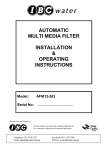
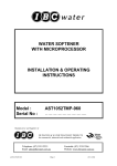
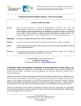
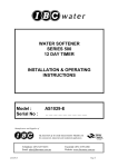
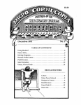
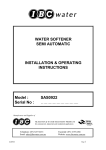
IRON & MANGANESE
REMOVAL FILTER
INSTALLATION
&
OPERATING
INSTRUCTIONS
Model :
Serial No :
AFIM20-180
………………………..
Manufacturer and Supplier of
FILTRATION & WATER TREATMENT PRODUCTS
for commercial, industrial and residential application
Telephone: (07) 3219 2233
Email: [email protected]
Facsimile: (07) 3219 2266
Website: www.ibcwater.com.au
Page 1
OPERATING PRINCIPLE
CONTINUOUS REGENERATION
General
Our AF Series Filters are fully automatic incorporating Backwash, Rinse-Pause, Fast Rinse
and Service Cycles, controlled by cam switches in the timer. Frequency of Backwashing can
be altered from that suggested in the commissioning section, if conditions dictate
alterations.
Water enters the unit through the multi-port valve and passes through the media,
underdrain gravel and the distributor leaving through the multi-port valve.
Iron, Manganese and Hydrogen sulphide are removed using media through oxidation and
filtration. Regeneration is required with Potassium Permanganate,
The oxidised precipitate is filtered out in the top layer of filter coal and the bottom layer of
manganese greensand media mainly acts as a barrier to remove any unprecipitated
iron/manganese.
The regeneration is automatically drawn from the regenerate tank and passed through the
media, thus effecting regeneration.
This unit is not designed to remove colloidal iron matter, a plant capable of
coagulation is required in such cases.
Operating Parameters
Water Temperature
5ºC - 50ºC
Water pH
6.8 - 8.8
Water Pressure
205 - 690 kPa
Oil
Free of Hydrocarbons
Maximum practical iron limit
15 mg/l of iron and manganese
Maximum practical limit hydrogen sulphide
5 mg/l
Minimum of 4 mg/l alkalinity for each mg/l of iron or iron manganese present
NOTE: If Filter will be in an area accessible to small children and pets, it is
strongly recommended that the Potassium tank be placed out of reach to avoid
accidents. The following label is attached to every Potassium Permanganate
container.
Please take note of caution label.
This unit is not designed to remove colloidal iron matter, a plant capable of
coagulation is required in such cases.
Page 2
AF SERIES FILTERS
Table 2
TYPE
M
a
n
g
a
n
e
s
e
MODEL
CONTINUOS
FLOW RATE
L.P.M
* PEAK
FLOW
RATE L.P.M
BACKWASH
FLOW RATE
L.P.M
VALVE
APPROX.
WEIGHT KG
AFIM20
39
62
82
180
300
&
G
r
e
e
n
s
a
n
d
Valve
Inlet
(mm)
Outlet
(mm)
Drain
(mm)
180
40
Operating Pressure: 205 - 690 kPa
Temperature: 5ºC - 50ºC
OPERATING
PROCEDURES
Water Temp: 5ºc - 50ºc
Water pH: 6.8 - 8.8
Suspended Solids
Max 50 mg/l
(Refer factory)
Iron & Manganese:
Max 15 mg/l
Oil: Free of
hydrocarbons
Alkalinity: 4 mg/l for
each 1 mg/l of iron and
or manganese.
Note: Due to the
complexities of iron,
manganese and
hydrogen sulphide it is
recommended that
product selection be
referred to IBC Water
Electrical: 240V 50Hz 3 watts maximum
Warning: A pressure reduction valve should be installed if water hammer prevails.
40
40
Table at left shows recommended MINIMUM plumbing sizes.
FAILURE TO OBSERVE WARNING WILL VOID WARRANTY
* The above flow rates are only suitable for an Iron/Manganese total content of 1 mg/l. Refer
to the factory for suitability of flow rates at a higher total metal content
Page 3
INSTALLATION
Check the equipment upon arrival for damage or shortages and report same to our Office or
Agent before commencing installation.
Locate the unit on a clean, firm, level foundation, preferably concrete, with sufficient space
for operation and maintenance. Level with shims if necessary. Position the tank in the
correct position before loading the Media. Make due allowances for space for maintenance
purposes.
1.
Make sure the filter tank is empty and clean.
2.
Install the distributor pipe in the filter tank, check the height in relation to top of filter
tank. The pipe must be level or 3mm below the top of the tank. The distributor
consists of a length of pipe with a bottom strainer and top disc.
3.
Place a clean rag or a plastic bag over the end of the distributor pipe - no gravel or
media must enter distributor pipe.
4.
Pour in the underbed gravel.
5.
Level out the underbed gravel - 40kg No. 6 Gravel
6.
After loading and levelling the gravel underbed, add the bags of manganese
greensand and level. Then fill the tank with water to approximately 300mm from the
tank top.
7.
Clean top of neck and threads of all traces of media. Remove the plastic cap fitted in
Step 3 taking care not to raise the distributor pipe.
8.
Unpack the valve, remove the cap screws and separate the adaptor. Store gasket
safely. Check that the tank seal is in place (Fig. 1). Remove the rubber sleeve and
using a little 'O' ring lubricant, lubricate the inside surface only. Place rubber sleeve
into tank adaptor (Fig. 1).
9.
Fit the adaptor to the tank, carefully, to allow the distributor pipe to enter the rubber
sleeve and locate centrally. Screw down firmly by hand. Do not over tighten. Place
the gasket on tank adaptor, fit the valve body with the cap screws provided (Fig. 1).
Tighten cap screws evenly.
10.
Plumb the unit, referring to figures 4 & 5 for pipework installation to suit the specific
unit, noting the following:
a) Use only pipe sizes recommended for this unit in the performance data Table 1
inside front cover of these instructions.
b) Fit pipe unions or flanges to inlet, outlet and drain lines for ease of access for
maintenance or cleaning.
c) Install inlet and outlet isolating valves and A Manual Bypass Valve - (Refer Fig. 4
Item C).
Page 4
d) Connect pipework and valves MUST be support to prevent loading on the valve
and filter. Before connecting pipework, flush or lines, close inlet, outlet and
bypass valves.
e) The drain line must discharge into open drain or pipe, with a maximum of 100mm
diameter and an air gap to conform to sanitary codes and permit observation, not
more than 7.6 metres from the unit.
f) Power supply is required not more than 1.5 metres from the unit and should be a
3 pin 10A 240V 50Hz G.P.O preferably earth leakage protected. Total power draw
is 13 watts maximum.
g) Fit external backwash flow controller using cap screws provided (Fig. 1).
h) Maximum operation pressure 450 kPa (65 p.s.i). Maximum operating pressure
690 kPa valve, this must be a non fluctuating supply.
The control system is sometimes shipped as a sub-assembly to avoid damage in transit.
The water filter should be assembled, piped and wired according to the following
recommendations. The following instructions are provided as a general guide. The filter
requires a 10amp 240 volt GPO. The filter installation must be protected from the elements
FIG.4 - INSTALLATION -- SINGLE TANK BIRM IRON REMOVAL FILTER INSTALLATION
* Pipework Layout - suggestive only
* Unit only supplied
* Pipe, Valves, Solenoids, Water Meter
External Backwash
supplied by others
Flow Controller
supplied separate
must be fitted before
Connecting Drain
Line
All pipework connections to be flanged
or barrel union, for ease of removal and
maintenance.
* USE PIPEWORK SIZES SHOWN IN
PERFORMANCE DATA TABLE 2
A
B
C
D
E
=
=
=
=
=
Inlet Isolating Valve -- Manual
Outlet Isolating Valve -- Manual
Bypass Valve -- Manual - optional
Water Meter - optional, fit only where metering of supply is required
Solenoid Valve - optional, fit only where raw water to service is not required during REGENERATION.
Valve must be 240V. 50Hz operation normally open and equal to pipeline size - connect to terminals 2
and 5 inside valve cover (Refer Fig.17)
FIG.5 - INSTALLATION -- MULTIPLE UNITS
Page 5
Page 6
625
Page 7
2097
1991
AFIM20-180 MANGANESE GREENSAND FILTER
MEDIA PLACEMENT
MANGANESE FILTER
Table 1
Sequence in Tank
AFIM20
1st
(in bottom of tank)
40kg #6 gravel
(2 x 20kg)
2nd
*200kg Manganese Greensand
(5 x 40kg)
Page 8
INSTALLATION OF POTASSIUM PERMANGANATE TANK
1.
Pour 2kg of Potassium Permanganate into the tank. A further 1kg container of
Potassium Permanganate should be added when the colour of the solution in the
Potassium Permanganate tank lightens in colour. If your hands or arms are stained,
the stain can be removed by washing with a softener mineral cleaner containing
sodium hydrosulphide. 1kg Potassium Permanganate is sufficient for two (2)
regenerations.
2.
Place the Potassium Permanganate tank as near as possible to the mineral tank.
a)
If filter will be in an area accessible to the general public and/or animals, it
is strongly recommended that this Potassium Permanganate Tank be placed
out of their reach to avoid accidents.
b)
The backwash waste water from the unit should not be pumped to an open
drain or any area accessible to the general public and/or animals.
POISON
NOT TO BE TAKEN
KEEP OUT OF REACH OF CHILDREN
POTASSIUM
PERMANGANATE
UN. No.
1490
3.
If external by-pass valve is used, be certain it is left in the SERVICE position after
installation is completed.
4.
The timer may be set for a regeneration frequency of from once in seven (7) days to
once each day. Determine a regeneration schedule and adjust the timer. To
calculate regeneration frequency it is assumed each person used 0.25 kl/day and
the capacity of the unit is:
For Iron Removal only
=
91.0 grams
For Iron and Manganese Removal
=
53.0 grams
Page 9
The following are examples of how to calculate regeneration periods:
Number of people
=
P
Iron content
=
A mg/L as Fe
Manganese
=
B mg/L as Mn
Number of regenerations per 7 days
=
P x 0.25 x A x 7
91
N (for Iron & Manganese removal)
=
P x 0.25 x (A+B) x 7
53
Always increase N to the next highest whole number.
Example:
Let P = 4 people
Then
A = 10mg/L Fe (iron) B = 0.2mg/L Mn (manganese)
N = 4 x 0.25 x 10.2 x 7
53
= 1.35 = 2
Then
In this case the number of pins to press IN will be two.
Note: The unit uses 500 grams of permanganate every regeneration.
The filter will regenerate on any numbered day having the regeneration pin pressed
inward and will skip days having the pins pulled fully outward. Normal factory setting
of the regeneration time is 2:30am. Plug must be in outlet having a constant 240 volt
AC power supply. The filter will regenerate automatically according to the preset
schedule. If an extra regeneration is desired because of heavy water usage
between regular regenerations, press RED knob to start automatic cycle. A period of
14 minutes will elapse before the cycle actually begins. This will not change the
normal schedule.
5.
Press the RED knob to initiate regeneration. When regeneration is complete the unit
will be ready for service.
Page 10
POTASSIUM TANK FLOAT VALVE
ADJUSTMENT OF VALVE
1. Lift float rod to full up position.
464-13
464-13
2. Set float to distance shown. Measure
from top of crown nut to the bottom of
the float.
464-9
MODEL
FLOAT DISTANCE (X)
464-10
AFIM20
180mm
464-11
NOTE: Float height should be such the
water is approximately 15-20mm above
shelf in regenerating tank.
464-15
464-10
464-16-B
464-16-C
464-16-D
464-16-E
464-16-G
464-16-A
464-16-F
464-6
464-2
464-1
464-4
PARTS LIST
Part No.
464 - 1
464 - 2
464 - 3
464 - 4
464 - 6
464 - 9
464 - 10
464 - 11
464 - 12
464 - 13
464 - 15
464 - 16 - A
464 - 16 - B
464 - 16 - C
464 - 16 - D
464 - 16 - E
464 - 16 - F
464 - 16 - G
Page 11
Description
Body
Plug
"O" Ring
Check Ball
Quad Ring
Float Rod
Float Grommet (2 Req)
Float
Float Rod Guide
Float Rod Guide Lock
Washer
Crown Nut
Ball Cage
Air Check Ball
Quad Cup Seat
Ball Cage Bottom
Stem
Spool Seat
COMMISSIONING
A period of (4) hours soaking should elapse after filling with water and potassium
permanganate before commissioning, so as to precondition the media.
Step 1:
Check plug is dry first, then connect lead into power outlet, switch on.
Step 2:
Remove clear cover from timer face by pulling the two black lock pins outward.
Depress the red knob (Fig. 14) and rotate anti-clockwise to backwash position,
release red knob, wait for valve drive to index to backwash position, (if not
already in this position) spindle fully out. (Fig.11).
Step 3:
Just open inlet isolating valve approximately 1.1/2 turns. Allow unit to fill slowly
(water will issue to drain) continue to run until the unit automatically indexes to
Pause position which may take up to 20 minutes. All air must be removed.
Step 4:
Depress the red knob and turn anti-clockwise until the microswitch trips into the
fast rinse position. Allow the valve to move fully into this position ie. Fig. 13. The
filter should then purge any remaining potassium permanganate to waste. Further
rotate the red knob anti-clockwise so that the arrow tip is pointing at about a
seven o'clock position. Then allow the red knob to advance electrically around to
the Service position. This may take up to 10 minutes.
Step 5:
Depress the red knob and turn anti-clockwise to start, release, the unit will now
go through each cycle - Backwash, purge and back to service automatically.
NOTE: A small amount of media may pass to drain during the initial backwash,
this is considered normal.
Step 6:
Check with site supervisor that unit can go on line. If so - slowly open outlet
isolating valve fully, check that manual bypass valve is fully closed. This unit is
now on line.
Step 7:
Check for and report any leaks.
Step 8:
Set the backwash frequency to Tuesday, Thursday and Saturday, if frequency of
backwash has not already been calculated. To set, PUSH the skipper pins IN on
the skipper wheel on days Backwashing is required.
Note: This is only a guide for initial setting and should be altered to suit each
individual installation in accordance with load conditions. If more than one
backwash per day is required the 440 Timer Knob will have to be replaced with a
special unit. Please consult the factory.
Page 12
Step 9:
Set time of day, pull timer knob (Fig. 14) and set arrow to the time of day (time of
your watch) release, make sure that the knob has re-engaged gear, knob right in.
Backwash will take place at approximately 2 a.m. If this time is not convenient it
will be necessary to offset the time of day setting to make allowances for the
desired time of backwashing. Eg. If 4 a.m. is desired, it will be necessary to set
the time of day two hours earlier than actual time.
Step 10: Replace the timer cover, depress the lock pins, wipe over unit.
Step 11: Do final check for leaks etc. Ensure instruction book is kept with relevant
personnel.
Step 12: Use Manganese Greensand only.
Step 13: Adjust the regenerate float as follows:
220 mm DRAW DOWN RATE - 11 mm/minute
Connect regenerant throttle valve at the rear of main valve and connect
regenerant throttle valve approximately 1.1/2 turns. The regenerant tank will fill,
add 3kg of potassium permanganate stir for 1 minute or until all crystals are
dissolved, open or close regenerant throttle valve until 11 mm/minute draw down
rate is attained
Page 13
DRIVE PISTON POSITIONING
(1) SERVICE POSITION
(3) BRINE AND SLOW RINSE POSITION
(2) BACKWASH POSITION
(4) FAST RINSE POSITION
SET TIMER
Determine a regeneration schedule for the conditioner
and adjust the automatic timer as follows:
1. Pull all SKIPPER PINS out (away from control).
2. Rotate SKIPPER WHEEL until DAY ARROW
points to day of week or number 1.
3. Depress SKIPPER PIN(S) for day(s) regeneration
is required.
4. Pull TIMER KNOB out (away from timer face) and
rotate until BLACK ARROW on tripper arm points
to correct time of day on Face Plate.
5. Timer will automatically initiate regeneration on
preset days at 2:30AM. To alter time, simply reset
TIMER KNOB to an earlier or later time, which
will change the time of regeneration by the same
number of hours. (Time indicated as BLACK
ARROW will no longer be correct).
FIG. 14
MANUAL OPERATION
Step 1. START-UP OR INSPECTION
REGENERATION
a) Push in RED KNOB and turn counterclockwise
past START to BACKWASH. Disconnect
electrical power and leave in position for desired
time. Reconnect electrical power.
b) Push in RED KNOB and repeat for all desired
cycles
Step 2. MANUAL INITIATION OF REGENERATION
a) Reconnect electrical power.
Page 14
b) Push in RED KNOB and turn counterclockwise to
the START position. Release. Unit will then go
through a complete regeneration as programmed.
BACKWASH CYCLE TIME INSTRUCTIONS
PIN TIME CHART
TYPICAL FILTER APPLICATION CYCLE
BACKWASH OR
FAST RINSE
NO. OF
TIME
PINS
OUT
1
8min.
2
11 min.
3
14 min.
4
17 min.
5
20 min.
6
23 min.
7
26 min.
8
29 min.
9
32 min.
10
35 min.
11
38 min.
12
41 min.
13
44 min.
14
47 min.
15
50 min.
PAUSE
NO. OF
PINS IN
TIME
2
3
4
5
6
7
8
9
10
11
12
13
14
15
16
1.5 min.
4.5 min.
7.5 min.
10.5 min.
13.5 min.
16.5 min.
19.5 min.
22.5 min.
25.5 min.
28.5 min.
31.5 min.
34.5 min.
37.5 min.
40.5 min.
43.5 min.
Backwash ………………….. 20 min. - 5 pins outward
Pause ………………………. 1.5 min. - 2 pins inward
Fast Rinse …………………. 11 min. - 2 pins outward
Each additional pin either pulled out or pushed in
equals 3 minutes
TIMER (REAR VIEW)
SET BACKWASH TIMING
Pull pins as shown for backwash time desired
- see chart.
SET PAUSE TIMING
Depress pins as shown for desired brine/rinse time
- see chart. (Minimum of two pins down)
SET FAST RINSE TIMING
Pull pins as shown for desired fast rinse time
- see chart
Page 15
REPLACEMENT PARTS
Page 16
VALVE ASSEMBLY PARTS LIST
Item
Description
No.
Required
1
1
1
1
1
1
5
1
1
4
Item
Description
49G
50G
51G
52G
53G
54G
55G
Screw
Nut
Limit Switch
Machine Screw
Cam Screw
Cam
Lock Washer
Drive Motor, 100v120v, 50Hz/60Hz
Drive Motor, 240v 50Hz
Drive Motor, 240v
50Hz/60Hz
Motor Screws
Wiring Harness
Drive Link Assy.
Drain Shut-off Valve
O Ring
Cover
Window Cover w/- Fasteners
Cover Window Cover
w/- Fasteners
Top Mount Adaptor - O Ring
Side Mount Adaptor (NPT)
Side Mount Adaptor (BSPP)
Distributor Seal
O Ring
12G
13G
14G
15G
16G
17G
18G
32G
33G
34G
Valve Body NPT
Valve Body BSPP
Injector Assy. small
Injector Assy. Med
Injector Assy. Large
1/2" Brass Pipe Plug
Cap Screw
Backwash Assy. BSPP
O Ring
Cap Screw
35G
Piston Assy.
1
58G
36G
37G
38G
39G
40G
41G
42G
Lower Cap Assy.
Cotter Pin
Manifold Gasket
Timer Lock
Motor Plate Assy.
Hex Head Screw
Ground Screw
1
1
1
1
1
10
1
59G
60G
61G
62G
63G
64G
65G
43G
Lock Washer
1
66G
44G
45G
46G
47G
48G
Nut
Screw
Switch Bracket
Terminal Strip
Marker Strip
1
2
1
1
1
67G
68G
69G
70G
71G
56G
57G
Page 17
No.
Required
2
2
3
2
1
1
2
1
1
1
4
1
1
1
1
1
1
1
1
1
1
1
1
SEVEN DAY 440 TIMER LIST OF PARTS
Item
14A
16A
3E
14F7
15F
18F
19F
84F
85F
87F
88F
Description
Cam Screw
Timer Mounting Screw
Limit Switch
Skipper Wheel - 7 Day
Friction Washer
Motor Mounting Screw
Wire Nut
Cover Plate
Screw
Compression Spring
Gear Retainer
No.
Required
1
3
2
1
1
2
2
1
4
1
1
Item
89F
99F4
1G
2G
3G
4G
5G
6G
7G
8G
9G
Description
Day Dial Washer
7 Day Tripper Assy.
Timer Bracket
Adjustable Cam
Timing Pin
O Ring
Retaining Washer
Switch Insulator
Switch Spacer
Switch Mounting Screw
Wiring Harness
No.
Required
1
1
1
1
36
1
1
2
2
2
1
WIRING DIAGRAM - 440
SIX-DAY OR SEVEN-DAY TIMER
FIG. 17
Page 18
MODEL 180 VALVE CAM POSITION
GENERAL MAINTENANCE
For correct operation the cam should be set to stop, the position at the point of each function.
This is done at the factory and rotation checked at this time. However, resetting may be
necessary from time to time should the unit fail to draw brine. Setting is simple, index position
to service position, (fully in), switch off power, loosen screw "A", adjust cam to position shown
above. Switch on power.
FIG. 19
Page 19
TROUBLE SHOOTING
GUIDE
AFIM20-180
Iron & Manganese Removal Filter
PROBLEM
REF. PAGE
UNIT WILL NOT BACKWASH AUTOMATICALLY
Page Twenty
UNFILTERED WATER TO SERVICE
Page Twenty
LEAK TO DRAIN
Page Twenty One
INSUFFICIENT SERVICE FLOW RATE
Page Twenty One
MINERAL TO SERVICE
Page Twenty Two
Page 20
1.
Unit will not Backwash Automatically
A)
B)
C)
IS THERE POWER TO THE UNIT ?
IS THE POWER CORD PLUGGED IN ?
IS THERE A REMOTE SWITCH IN THE LINE ISOLATED ?
check these possibilities, and correct if necessary
D)
IS THE TIMER MOTOR RUNNING
if the timer motor is running, the small driven gear on the timer motor will be
turning. If not, replace the timer motor.
E)
BACKWASH DRIVE GEAR NOT ENGAGED
check gear behind push button on timer for proper alignment, and time of day
lever is down and fully engaged.
F)
VALVE MOTOR MICRO SWITCH NOT OPENING OR CLOSING
adjust micro switch stack (Fig. 19)
G)
VALVE MOTOR MICRO SWITCH BURNED OUT
replace micro switch
H)
VALVE MOTOR MICRO SWITCH NOT OPENING OR CLOSING
replace micro switch
I)
TIMER MOTOR SWITCH BURNED OUT
replace micro switch
2.
Unfiltered Water to Service
A)
RUBBER SLEEVE MISALIGNED OR MISSING AT TOP OF DISTRIBUTOR PIPE
remove valve head and replace rubber sleeve
B)
UNIT INSTALLED BACKWARD
check arrow markings on top of valve head for correct inlet/outlet plumbing
C)
REFER SECTION 1 FOR FURTHER INFORMATION
D)
BYPASS VALVE NOT CLOSED
check operation
E)
INSUFFICIENT DOSING OF POTASSIUM PERMANGANATE
Page 21
check sample prior to filter
F)
3.
pink?
INSUFFICIENT BACKWASH FREQUENCY
increase backwash frequency
Leak to Drain
A)
CHECK PLUNGER POSITIONING
refer Fig. 12
B)
CHECK DRAIN SHUT-OFF 'O' RING
located in upper cap (refer Part No. 35G)
4.
Insufficient Service Flow Rate
A)
VALVE NO OPENING
(Units equipped with optional service isolation valve)
the valve must open fully when in service
dirt, rust, scale, etc. May prevent the valve from opening
disassemble and clean
B)
UNIT MAY BE FOULED WITH SUSPENDED SOLIDS
backwash and check again
C)
SERVICE INLET OR OUTLET VALVE NOT FULLY OPENED
ensure they are opened
D)
PISTON OUT OF POSITION
reposition (refer Fig.10)
E)
INSUFFICIENT WATER PRESSURE
check
5.
Mineral to Service
Page 22
A)
RUBBER SLEEVE MISALIGNED OR MISSING AT TOP OF DISTRIBUTOR PIPE
remove valve head and replace rubber sleeve
B)
UNIT INSTALLED BACKWARD
check arrow markings on top of valve head for correct inlet/outlet plumbing
C)
BACKWASH FLOW RATE EXCESSIVE
check flow control
D)
RISER PIPE OR BOTTOM STRAINER BROKEN
remove media and replace riser tube assembly
Page 23