1
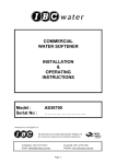
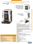
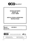
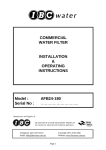
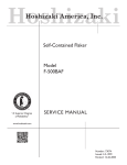
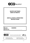
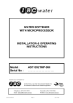
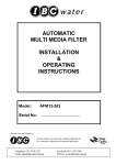
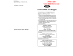
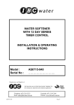
COMMERCIAL
WATER SOFTENERS
INSTALLATION & OPERATING
INSTRUCTIONS
Model :
Serial No :
AS20150-180
………………………..
Manufacturer and
FILTRATION & WATER TREATMENT PRODUCTS
for commercial, industrial and residential application
Telephone: (07) 3219 2233
Email: [email protected]
AS20150-180
Facsimile: (07) 3219 2266
Website: www.ibcwater.com.au
Page 1
INSTALLATION
Check the equipment upon arrival for damage or shortages and report same to our Office or Agent before
commencing installation.
Locate the unit and brine tank on a firm level foundation, preferably concrete, with sufficient space for
operation and maintenance. Level with shims if necessary, paying particular attention to the brine tank
being placed on a flat clean surface. Position the tanks in their correct position before loading the Media.
Make due allowance for space for maintenance purposes and for the brine tank salt replenishment.
FIG.4 - INSTALLATION -- SINGLE TANK SOFTENER INSTALLATION
* Pipework Layout - suggestive only
Flow Controller
supplied separate
must be fitted
before Connecting
Drain Line
* Unit Only supplied
* Pipe, Valves, Solenoids, Water Meter
supplied by others
All pipework connections to be flanged
or barrel union, for ease of removal and
maintenance.
* USE PIPEWORK SIZES SHOWN IN
PERFORMANCE DATA TABLE 1
A
B
C
D
=
=
=
=
E =
BRINE
TANK
Inlet Isolating Valve -- Manual
Outlet Isolating Valve -- Manual
Bypass Valve -- Manual - optional
Water Meter - optional, fit only
where metering of supply is required
Solenoid Valve - optional, fit only where raw water to service is not required during
REGENERATION. Valve must be 240V. 50Hz operation normally open and equal to pipeline size connect to terminals 2 and 5 inside valve cover (Refer Fig.12)
BRINE
TANK
AS20150-180
BRINE
TANK
Page 2
MEDIA INSTALLATION
Step 1:
Remove the tank and riser tube assembly from the carton and make sure the
softener tank is empty and clean.
Step 2:
Cover the riser pipe with a clean rag or plastic so that NO gravel or media
enters the riser pipe, and hold the pipe down firm on the tank bottom.
Step 3:
Pour in the underbed gravel (No.6). Refer Table 1. 40kg.
Step 4:
Level out the underbed gravel using a broom handle/PVC pipe. The underbed
gravel should cover the bottom screen of the riser pipe by about 25mm.
CAUTION:
Do not raise the riser pipe. If gravel is allowed to get under the
distributor, empty and start again.
Step 5:
Load the resin. The resin is shipped in 25L bags. Refer Table 1.
Step 6:
Fill the tank with water to 50mm from the top.
Step 7:
Clean top of tank (neck & threads) of all traces of resin. Remove the rag or
plastic fitted in Step 2, taking care not to raise the riser pipe.
Step 8:
Unpack the valve, remove the cap screws and separate the adaptor. Store
gasket safely. Check that the tank ‘O’ ring seal is in place. Using a little silicone
“O” ring lubricant, lubricate the inside surface of the Riser pipe ‘O’ Ring seal ..
Refer Valve Assembly .
NOTE:
The softener will not produce soft water if the rubber Riser Pipe ‘O’ Ring
is not in position correctly or is damaged.
Step 9:
Fit the adaptor to the tank, carefully, to allow the riser pipe to locate centrally.
Screw down firmly by hand. Do not over tighten. Place the gasket on the tank
adaptor, fit the valve body with cap screws provided. Tighten cap screws
evenly. Refer valve assembly.
Step 10: Screw the brine throttle gate valve assembly provided into the 180 Valve brine
port located between the inlet and the outlet fittings.
AS20150-180
Page 3
Step 11: Remove the brine valve from the brine well of the brine tank. Ensure brine tank
is free from foreign matter and set brine valve as follows:Determine if wet salt or dry salt is required, using the formula shown in
“Determining Frequency of Regeneration”. If sufficient information is not
available to do the calculations shown in “Determining Frequency of
Regeneration”, contact our office. The brine valve is supplied factory fitted
with a dry salt riser, a wet salt riser is also supplied (short black screwed riser
pipe ). Store the riser tube not used, DO NOT DISCARD it may be needed at
commissioning. Adjust the brine valve float height based on the
calculations.
Step 12: Replace the brine valve in the brine well and connect brine tube - this tube is
supplied long and can be cut to the desired length. Leave sufficient length to
remove brine valve from brine well without disconnecting from the tube.
Step 13: Now add the gravel (No.4) to the brine tank. Ensure no gravel enters brine well.
Models AS20150 require 40kg. Refer Table 1.
Step 14:
Add salt to the tank (Refer Table 3 for correct quantity). Replace lid.
Step 16: Plumb the unit, refer to Fig.4 & 5, noting the following:a)
b)
c)
d)
e)
f)
g)
h)
i)
j)
AS20150-180
Check arrow markings on the valve for correct inlet/outlet plumbing .
Use only pipe size recommended in Table 2.
Fit pipe unions or flanges to inlet, outlet, and drain line for ease of access
for maintenance or cleaning.
Install inlet and outlet isolating valves and a Manual Bypass Valve.
Install optional solenoid and/or water meter if required. Ref. Fig 4&5.
Connecting pipe work and valves MUST be supported to prevent loading
on the valve and pipe work. Before connecting pipe work, flush all lines,
close inlet, outlet and bypass valve.
The drain line must discharge into an open pipe at least 80mm diameter
no more than 7.5 metres from the unit. An air gap of 100mm should be
allowed for inspection and to conform to sanitary codes.
Power supply is required not more than 0.5 metres from the unit and
should be a 3 pin 10amp 240v 50Hz GPO preferably earth leakage
protected. Total power draw, 13 watts maximum.
Fit external backwash flow controller using cap screws provided.
Minimum operating pressure 205 kPa (30psi), maximum operating
pressure 690 kPa (100psi). If supply pressure is above 690 kPa, fit
pressure reducing valve. This must be a non-fluctuating supply. Water
hammer and excess pressure will void factory warranty.
Page 4
DETERMINING FREQUENCY OF REGENERATION
After locating and installing the brine tank in the required position, it is necessary to
know whether a wet or dry salt system is to be used. This is done by calculation as
follows:NOTE:
Less salt is required to regenerate a partially exhausted bed per gram of
hardness removed, than that required for a more exhausted bed. For
economy sake regenerate before full exhaustion.
Calculate time between regenerations thus:C
-----------
=
N
HxQ
Where
C
=
maximum capacity of unit as grams of CaCO3
(Refer Table 2)
H
=
hardness of water a mg/l or ppm.
Q
=
amount of water passed through the unit in kilolitres per
day.
N
=
maximum time between regenerations in days.
The calculated value of N should be taken down to the nearest whole number. This
is the maximum number of days which can be achieved between regenerations.
The amount of salt needed per regeneration, is calculated thus:Total hardness removed (Exchange Capacity Required) = N x H x Q = A
Where A = the total hardness removed as grams of CaCO3
The salt dosage for the exchange capacity required is found in Table 2.
AS20150-180
Page 5
EXAMPLE:
Softener AS16100
Litres of resin “150” from Table 1
Hardness of water 110 mg/l
Flow 3.5kl/hr for 24 hours /day.
Q
H
C
=
=
=
3.5 x 24
=84 kl./day
110 mg/l or ppm
10500 grams
Frequency of regeneration N
=
C
HxQ
=
10500
110 x 84
=
1.13 day
Always go down to the nearest whole number (1 day).
Exchange Capacity A
=
=
=
NxHxQ
1 x 110 x 84
9240 grams
The minimum, medium and maximum capacities of a single unit from Table 2 are 5250,
7900 and 10500 respectively. The calculated capacity falls closer to the higher and so
the higher value must be used. The Higher nearest Capacity must be used at all times.
Salt dosage required for 10500 g is 36 kg (from Table 2).
Now looking at Table 4 we find that both wet and dry salt can be used. However, if
your calculated salt dosage allows you the choice of either dry or wet salt always
choose dry salt.
In the case of the example the salt dosage is 36 kg so the float setting is 350 mm (refer
Brine Tank Set-up for float setting details), and the draw down rate should be adjusted to
17mm.per minute.
Install the brine valve as shown in the illustration for Brine System setup.
The initial salt load as shown in Table 3 should be loaded into the brine tank.
IMPORTANT NOTE:
The water softener, as supplied, has the brine riser pipe assembled to suit dry salt
brine system. If, however, on reference to Table 4 you find that wet salt must be
used, then wet salt brine rise pipe (short black pipe piece supplied) must be fitted
to the brine valve.
AS20150-180
Page 6
AS20150-180
Page 7
COMMISSIONING
Step 1:
Remove valve cover by partly unscrewing the three cover securing screws and
lifting the cover forward. Remove the clear plastic window in the cover by
removing two screws and loosening the other two screws and sliding the
window out. Replace the cover on the valve. Connect the power lead to the
power point and turn on the electric power. Depress the red knob (Fig. 7) and
rotate anti-clockwise to backwash position, release red knob, Note that the
timer face design can vary between valve models from that illustrated and that
the regeneration positions are indicated pictorially with Backwash being Flow
show in a Upward direction and the other regeneration positions shown with
their corresponding flow path. Wait for valve drive to index to backwash
position, (if not already in this position) that is the spindle is fully extended.
Ensure that the brine throttle/stop valve is fully closed.
Step 2:
Just partly open inlet isolating valve. Allow unit to fill slowly (water will issue
to drain) continue to run until the unit automatically indexes to brine rinse
position which may take up to 15 minutes. This allows all the air to be removed.
Step 3:
Depress the red knob again and rotate anti-clockwise to the fast rinse position
and release. Verify that the spindle has moved to it’s correct position as
indicated in the following illustrations.
Step 4:
Open brine throttle/stop valve approximately 1.1/2 turns, fully open inlet
isolating valve. Allow brine tank to fill until brine float valve shuts off. Generally
it takes at least four hours to develop saturated brine, however new resin is in a
fully regenerated state so it is only necessary to allow a half hour brine soak.
Allow the red knob to return to the service position. It is recommended to
give the softener a full regeneration so as to remove any colour throw and to
further condition the resin. Depress the red knob and turn anti-clockwise to the
start position or the first arrow position just anticlockwise from the service
position then release the red knob, the unit will now go through each cycle Backwash, brine rinse, purge and back to service automatically, the full cycle
will take approximately 90 minutes, depending on pin settings.
NOTE:
A small amount of media may pass to drain during the initial backwash, this is
considered normal. When unit commences brine and rinse cycle, adjust
brine throttle/stop valve to the correct draw down rate. Ref. Table 4. This
draw down rate is checked by means of a tape measure from the top of the
brine surface in the brine well and is the draw down rate in mm per minute.
Step 5:
Check with site supervisor that unit can go on line. If so - slowly open outlet
isolating valve fully, check that manual bypass valve is fully closed. This unit is
now on line.
AS20150-180
Page 8
Step 6:
Check for and report any leaks. Go to nearest tap, now on soft water, open and
allow to flow for a few minutes. Using test kit to test for soft water - refer to
Hardness Testing in back of these instructions. It may take several minutes for
the soft water to pass to the tap. If hard water persists refer to the Trouble
Shooting in these instructions. Check that the brine tank is full and that the float
has shut off.
Step 7:
In the calculations you have done (determining regeneration frequency) you
found the value for (N) - maximum time between regeneration in days. To
set the skipper wheel up as required, pull all skipper wheel pins out.
Turn the dial to the correct day of the week (note dials may be indicated
as the actual day of week or as numbered days of the week) on which you
are setting the dial. Now depress the pins for the desired day/s for
regeneration/s required. If no data is available to do the calculations at
this stage then set regeneration for every second day.
Note: When you are setting the regeneration frequency you should take
into account the working days, for instance if the installation will only
work week days, regeneration on Friday and Monday would be a needless
waste of salt. Always set in accordance with the duty conditions for
maximum economy.
NOTE:
This is only a guide for initial setting and should be altered to suit each
individual installation in accordance with load conditions - do the calculations in
determining frequency of regeneration, it will help you in understanding the
softener.
Step 8:
Set time of day, pull timer knob and set arrow to the time of day (time of
your watch) note time of day may be as 12 hour or 24 hour clock, release,
make sure that the knob has re-engaged gear, ie. knob right in.
Step 9:
After the softener has done the first regeneration and the regeneration
sequence and time of day has been set, turn off the electric power and
remove the valve cover ,then replace the clear plastic window in the cover
and then replace the valve cover on to the valve and reconnect the electric
power. This unit is now on line.
Step 10: Do final check for leaks etc. Ensure instruction book is kept with relevant
personnel.
AS20150-180
Page 9
HARDNESS TEST
1.
Water to be tested should be taken from a tap after the water softener
2.
Measure 10ml of water into plastic bottle supplied (approximately 1/3 full)
3.
Add one Yes/No tablet to sample water, replace cap and shake until tablet
has completely dissolved.
(NOTE: do not handle Yes/No tablet with fingers)
4.
The final colour to be obtained for soft water is green. (Note: The shade of
green may vary.) If the colour turns red, the water is above 20 mg/l
hardness, therefore another regeneration is recommended.
5.
Rinse plastic bottle after each test has been completed.
6.
When used as above, the tablets change the colour from green to red at a
hardness of approximately 20ppm based on a sample volume of 10mls.
Other hardness test kits are available for more accurate testing eg.
Hardness Tablets
Directions:
Take a 50ml sample of water in a screw capped bottle. Add one (1)
tablet to sample, shake or crush to disintegrate. Repeat until last
trace of reddish tinge disappears. The final colour is usually blue but
with some water a greyish coloured end point is obtained.
Using 50ml sample Hardness ppm = (number of tablets x 40) - 20
LR (BW) Tablets
Directions:
Take a 100ml sample of water in a screw capped bottle. Add one (1)
tablet to sample, shake or crush to disintegrate. Repeat until last
trace of reddish tinge disappears. The final colour is usually blue but
with some water a greyish coloured end point is obtained.
Using 100ml sample Hardness ppm = (number tablets x 2) - 1
Contact IBC Water if further details are required.
AS20150-180
Page 10
PERFORMANCE DATA
Table 1
Model
MEDIA LOADING
Underbed Gravel No.6
Resin Content
kg
litres
AS20150
40
Brine Tank Gravel No.4
kg
40
150
Table 2
Service Flow
Rate
Capacity
&
Salt Dosage
Timer
Control
Model No.
Minimum
Medium
Maximum
Peak
Flow
grams/kg
AS20150
5250/10
7900/20
Contin
uous
Flow
Pipe Size
Inlet
Outlet
l/m
10500/36
150
40
Approx.
Shipping
Weight
Drain
mm
106
Resin
Volume
40
Space
Requirements
W xDxH
litres
wt/kg
metres
150
290
1.2x0.9x2.2
Peak flow not recommended for extended periods of time.
Brine Tank:
Poly moulded construction complete with lid.
Brine Valve:
Plastic construction.
Operation Pressure:
205 - 609 kPa (30psi - 100psi)
Note: Minimum pressure may vary depending on salt
dosage - consult factory.
Temperature:
5 - 48 degrees C
Electrical:
240v 50Hz 3w maximum
WARNING:
A pressure reduction valve should be installed in areas of high water
pressure (above 690 kPa ).
A water hammer arrester should be installed if water hammer
prevails.
FAILURE TO OBSERVE WARNINGS WILL VOID WARRANTY
AS20150-180
Page 11
Model AS20150
Brine System
Initial Salt Loading
Dry
Wet
350 kg
120 kg
Table 4
Brine Tank Size 600mm dia x 1200 high
Float Setting (mm)
Brine Draw Down Rate (mm/min)
Salt Dosage
(Kg)
10
14
16
24
30
36
AS20150-180
Dry Salt System
Float Setting
170
260
300
480
610
-
Draw Down Rate
8
13
15
24
30
-
Wet Salt System
Float Setting
135
215
280
350
Draw Down Rate
7
11
14
17
Page 12
Note: Timers may vary from that illustrated in that the Ti
Skipper Wheel may show the actual days of the week an
illustrations showing the water flow path with the start p
clockwise from the service position
Setting Timer
Determine a regeneration schedule for the
conditioner and adjust the automatic timer as
follows (Reference Figures 7 & 8):
1. Pull all the skipper pins out (away from
control).
2. Rotate skipper wheel until day arrow points to
day of week or number 1.
3. Push in skipper pin (s) for day (s) regeneration
is required.
4. Pull Timer Knob out (away from the timer face)
and rotate until time arrow on timer knob points
to correct time of day on face plate.
5. Timer will automatically initiate regeneration on
preset days at 2:30 A.M. To alter time, simply
reset timer knob at an earlier or later time
which will change the time of regeneration by
the same number of hours. (Time indicated at
time arrow will no longer be correct.)
Regeneration Cycle Time
Instructions
Pin Time Chart
Backwash or
Fast Rinse
No of
Pins Out
1
2
3
4
5
6
7
8
9
10
11
12
13
14
15
*
Time
8 min.
11 min.
14 min.
17 min.
20 min.
23 min.
26 min.
29 min.
32 min.
35 min.
38 min.
41 min.
44 min.
47 min.
50 min.
Brine / Rinse
No of
Pins In
2
3
4
5
6
7
8
9
10
11
12
13
14
15
16
*
Time
1.5 min.
4.5 min.
7.5 min.
10.5 min.
13.5 min.
16.5 min.
19.5 min.
22.5 min.
25.5 min.
28.5 min.
31.5 min.
34.5 min.
37.5 min.
40.5 min.
43.5 min.
* Each additional pin either pulled out or pushed in
equals 3 minutes.
Set Backwash Timing
Figure 7
Pull pins as shown for desired backwash time.
Reference Pin Time Chart.
Set Brine/Rinse Timing
Depress pins as shown for desired brine/rinse time,
minimum of two pins down. Reference Pin Time
Chart.
Set Fast Rinse Timing
Pull pins as shown for desired fast rinse time.
Reference Pin Time Chart.
AS20150-180
Page 13
Valve Positions
Typical Water Conditioning Cycle
Backwash ……. 14 min. ……… 3 pins outward
Brine / Rinse … 40.5 min. ……. 15 pins inward
Fast Rinse …… 11 min. …..….. 2 pins outward
1. Back Position
Variation Water Conditioning Cycle
Backwash ……. 14 min. ……… 3 pins outward
Brine / Rinse … 85.5 min. ……. 30 pins inward
Fast Rinse …… 11 min. …..….. 2 pins outward
2. Brine and Slow Rinse position
3. Fast Rinse position
Manual Initiation of Regeneration
Push in Red Knob and turn COUNTERCLOCKWISE to START position. Release. Unit will
go through a complete regeneration as
programmed.
4. Service position
AS20150-180
Page 14
ELECTRICAL DIAGRAMS
Wiring Diagram 440 Six-Day or Seven-Day Timer
Wiring Diagram 450 Impulse Timer
Figure 13
AS20150-180
Page 15
FLOW SCHEMATIC
AS20150-180
Page 16
Injector Flow Rate Chart
A Injector
Draw
Rinse
PSI (Kg/cm)
20 (1.4)
30 (2.1)
60 (4.2)
80 (5.6)
100 (7.0)
B Injector
Draw
Rinse
C Injector
Draw
Rinse
Gpm (Lpm)
Gpm (Lpm)
Gpm (Lpm)
Gpm (Lpm)
Gpm (Lpm)
Gpm (Lpm)
0.7 (2.6)
1.1 (4.1)
1.3 (4.9)
1.4 (5.3)
1.4 (5.3)
.8 (3.0)
1.0 (3.8)
1.2 (4.5)
1.4 (5.3)
1.5 (5.7)
.8 (3.0)
1.2 (4.5)
1.3 (4.9)
1.5 (5.7)
1.5 (5.7)
1.2 (4.5)
1.6 (6.0
1.7 (6.4)
2.0 (7.6)
2.2 (8.3)
.8 (3.0)
1.2 (4.5)
1.5 (5.7)
1.7 (6.4)
1.8 (6.8)
2.2 (8.3)
2.8 (10.6)
3.3 (12.5)
3.8 (14.4)
1.4 (15.5)
Pressure Drop vs. Flow
PSI (Kg/cm)
SERVICE (Cv 12.9)
Gpm (Lpm)
SERVICE (Cv 6.1)
Gpm (Lpm)
SERVICE (Cv 9.6
Gpm (Lpm)
5 (0.35)
10 (0.70)
15 (1.00)
20 (1.40)
25 (1.70)
30 (2.10)
29 (110)
40 (151)
50 (189)
58 (220)
64 (242)
70 (265)
13 (49)
19 (72)
23 (86)
26 (98)
30 (114)
32 (121)
20 (76)
30 (114)
37 (140)
44 (167)
48 (182)
53 (201)
AS20150-180
Page 17
AS20150-180
Page 18
Parts List
REF.
#
PART NO
1
1034502
1034506
2
3
4
5
6
1034936
1034931
1034934
1034170
1034173
1010301
1003062
1006285
1035018
7
1034704
1034705
1034706
1034707
1034708
1034709
1034710
1034711
1034712
1034713
1034714
1034715
1034700
1034701
1006266
8
9
10
11
12
13
14
15
1035159
1010130
1035069
1005222
1010144
1010136
1035022
1034940
1034961
1034962
16
17
18
1005580
1033889
1008332
19
1005850
20
1035156
AS20150-180
DESCRIPTION
Valve body:
NPT
BSPT
Injector Assembly:
"A" (Yellow)
"B" (Orange)
"C" (Gold)
Blank (undrilled)
Injector Screen
Injector o-ring (2 Required)
Injector Plug, 1/2 In NPT
Cap Screw, 5/16-18 x 2 3/4
(5 Required)
Gasket, Upper Cap
Backwash Assembly:
4 gpm, NPT
4 gpm, BSPT
5 gpm, NPT
5 gpm, BSPT
6 gpm, NPT
6 gpm, BSPT
10 gpm, NPT
10 gpm, BSPT
15 gpm, NPT
15 gpm, BSPT
25 gpm, NPT
25 gpm, BSPT
Open, NPT
Open, BSPT
Cap Screw, 5/16-18 x 3/4
(4 Required)
Drain Shut-off
O-ring
Piston Assembly
Cotter Pin
O-ring
O-ring
Cap
24VAC Drive Motor Assembly
120VAC Drive Motor
Assembly
230VAC Drive Motor
Assembly
Screw, Hex Hd., 8-32 x 3/4
Cam Assembly
Switch (3 Required)
Included with item 15
Screw, Hex Hd., 10-24 x 1/2
(6 Required)
Bracket, Switch
REF.
#
PART NO
21
22
23
24
1077710
1035085
1035041
1077699
25
1078196
26
SCS-0070
27
1005585
28
29
30
31
32
33
34
1077798
1035042
1034851
ORE-347
ORE-225
1077721
1034524
DESCRIPTION
Wire Guide Bushing, .875
Drive Link Assembly
Gasket (Valve to Motor Plate)
Nut, Keps, 6-32, Plated Steel
(4 Required)
Screw, Hex Hd., 10-32 x 3/8
(3 Required)
Screw, 6-32 x 3/8 Round Head
(4 Required)
Screw, Hex Hd., 1/4-20 x 3/8
(10 Required)
962-180 Turbine Meter Cable
Gasket (Valve to Adapter)
Adapter Kit, Top Mount
O-ring
O-ring
Cover
Side Mount Adapter
962 Electronic Control Parts (Sub-Assy. P/N 1077719)
35
36
37
38
39
1077713
1076297
ZHDW4152
650022
SCS-0064
40
SCS-0054
41
42
43
44
45
46
1075767
1075721
1075768
1075764
1070488
1075766
47
48
49
1077706
1070491
1077915
Wire Harness Assembly
PWA Assembly 962
Marker Strip, 11-20
10 Terminal Block
Screw, 4-40 x 5/8 Round Head
(2 Required)
Screw, 2-56 x 1/4 ph/pnhd
(2 Required)
Battery Clip, 962
Wire Harness, 10 Cond., 962
Battery, NiMH, Battery, 9V
Wire Harness, Battery, 9V
Keypad, Membrane, 962
Screw, 8-32 x 1/4 ph/flhd
(4 Required)
PWA Mounting Bracket 962
Realy, SPDT, 12VAC, 962
Screw, 4-40 x 1/4 ph/pnhd, stl,
SEMS
(4 Required)
440 or 450 Timer Parts
50
51
52
1035047
53
54
55
1035479
1077751
1035431
Timer Mounting Bracket
Timer Assembly
Screw, 8-32 x 1/4
(4 Required)
Wire Harness Assembly
Window
Timer Lock
Page 19
Hydrostatic Test Pressure …………………………………………………………………………. 250 psi (17.2
bar)
Working Pressure ……………………………………………………………………… 20 - 100 psi (1.38 - 6.89
bar)
Standard
Electrical
Rating
………………………………………………………………………………….
120V/60Hz
Optional Electrical Rating (Timers) …. 24V/50Hz, 24V/60Hz, 120V/50Hz, 100V/60Hz, 100V/50Hz,
230V/50Hz
Optional Electrical Rating (962 Controller) …………………………………………………………… 230V
50/60Hz
Electrical Cord (when furnished, with standard rating) ………………………………………... 6ft, 3 wire with
plug
Electrical Connection …………………………………………………………………………………… Terminal
Strip
Electrical Plumbing Connection ……………………………….. 1-1/2 in NPT inlet, outllet top and bottom of
tank;
1/2 in NPT brine; in NPT
drain
Rubber Parts …………………………………………………………………… Compounded for cold water
service
Valve Body
…………………………………………………………………………………………………………
Brass
Injector …………………………………………………………………. 3 sizes available: A, B, C. (Refer to Page
*)
Program Clock ………………………………… 6 or 7-day English language or international symbols
inscription
Microprocessor Demand system and Impulse Timers also
available
Backwash
Cycle
……………………………………………………………………………………………...
Adjustable
Brine/Rinse
Cycle
……………………………………………………………………………………………
Adjustable
AS20150-180
Page 20
Fast
Rinse
Cycle
……………………………………………………………………………………………..
Adjustable
Total
Regeneration
Time
……………………………………………………………………………………
Adjustable
External Backwash Controller required (over 25 gpm) ………………………………. Sized to media
requirement
External Brine Valve Required ……………………………… Must have positive shut-off on refill and draw
down
Ambient Temperature ………………... 34°F (1°C) to 120°F (49°C). Valve to be drained if possiblity of
freezing
Riser Pipe Diameter Required ……………………. 1-1/2 in schedule 40 PVC (42.16 mm O.D. x 3.81 MM
wall)
AS20150-180
Page 21
Model 180 Valve Cam Position
General Maintenance
For correct operation the cam should be set to stop, the position at the point of each
function. This is done at the factory and rotation checked at this time. However, resetting
may be necessary from time to time should the unit fail to draw brine. Setting is simple,
index piston to service position, (fully in) switch off power, loosen screw “A”, adjust cam to
position shown above. Switch on power.
AS20150-180
Page 22
BRINE TANK SETUP
AS20150-180
Page 23
WET SALT:- SHORT RISER
DRY SALT:- LONG RISER
BRINE VALVE ASSEMBLY
FLOAT DISTANCE
TABLE 4
Float Setting
To adjust float:
Hold float rod in full up position and slide float to
correct position for setting using rubber
grommets to hold float in correct position.
PART NUMBERS:
H7070-01
H7070-02
H7070-03
H7070-04
H7070-05
H7070-06
H7070-07
H7070-08-36"
H7070-08-54"
AS20150-180
Body
PL Plug-3/4"
Seat Washer
Check Ball
Ball Cage
O-ring Cover Seal
Body Cover
Float Rod and
Seat Cone - 36"
Float Rod and
Seat Cone - 54"
H7070-09
H7070-10
H7070-12
H7070-13
H7070-14
H7070-15
H7070-16
H7070-17
H7070-18
H7070-19
SS Cover Screw
SS Lock Washer
Float Grommet
3 1/2" Bell Float PP
Float Rode Guide
Guide Screw (not shown)
Upper Seat retainer
Refill Chamber
Lower Seat Chamber
O-ring Refill
Chamber Seat
Page 24
AS20150-180
Page 25
TROUBLE SHOOTING
GUIDE
AS 16100 to AS24300
SOFTENERS
PROBLEM
REF. PAGE
FAILURE TO DRAW BRINE
Page 25
MINERAL TO SERVICE
Page 26
INSUFFICIENT SERVICE FLOW RATE
Page 26
HARD WATER TO SERVICE
Page 27
OVERFLOWING BRINE TANK
Page 28
UNIT WILL NOT REGENERATE AUTOMATICALLY
Page 28/29
LEAK TO DRAIN
Page 29
SALT IN SERVICE LINE
Page 29
AS20150-180
Page 26
.1.
Failure to Draw Brine
A)
BRINE THROTTLE /STOP VALVE CLOSED
⇒
open the brine shut-off valve fully
⇒
readjust for correct brine draw down rate
B)
LOW WATER PRESSURE
⇒
water pressure should be at least 205 kPa (30psi)
C)
BLOCKED STRAINER ABOVE NOZZLE
⇒
remove plug No 3 Page 16
D)
BLOCKED NOZZLE
⇒
remove the nozzle plug and clean the nozzle and throat
⇒
use caution to prevent cross threading when they are reinstalled
E)
AIR LEAKS IN BRINE LINE
⇒
salt deposits or corrosion usually are evident at joints which will leak air
⇒
clean the joints and use pipe tape on threads to ensure tight seals
⇒
clean union seats and tighten the bonnet on the bine shut-off valve
F)
WORN VALVE PISTON SEALS
⇒
replace plunger assembly
G)
RESTRICTION IN BRINE VALVE OR BRINE LINE
⇒
remove restriction
H)
RESTRICTION IN BACKWASH FLOW CONTROLLER
⇒
clean flow controller
⇒
remove any deposits from flow control rubber/s
I)
BRINE WELL FILLS TOO FAST, SHUTS OFF BRINE VALVE PREMATURELY
⇒
make sure refill ball check is in base of brine valve
J)
SEDIMENT BUILD-UP IN BOTTOM OF BRINE TANK
⇒
clean brine tank
K)
PISTON OUT OF TIME
⇒
readjust piston and readjust motor cam
L)
VALVE MICRO SWITCH NOT OPENING OR CLOSING
⇒
adjust micro switch
AS20150-180
Page 27
.2.
Mineral to Service
A)
RUBBER ‘O’ MISALIGNED OR MISSING AT TOP OF DISTRIBUTOR PIPE
⇒
remove valve head and replace rubber ‘O’ ring
B)
UNIT INSTALLED BACKWARD
⇒
check arrow markings on top of valve head for correct inlet/outlet
plumbing
C)
BACKWASH FLOW RATE EXCESSIVE
⇒
check flow controller
D)
RISER PIPE OR BOTTOM STRAINER BROKEN
⇒
remove media and replace riser tube assembly
.3.
Insufficient Service Flow Rate
A)
(Units equipped with optional service isolation valve)
VALVE NOT OPENING
⇒
the valve must open fully when in service
⇒
dirt, rust, scale, etc. may prevent the valve from opening
⇒
disassemble and clean
B)
UNIT MAY BE FOULED WITH SUSPENDED SOLIDS
⇒
backwash and check again
C)
SERVICE INLET OR OUTLET VALVE NOT FULLY OPENED
⇒
ensure they are opened
D)
PISTON OUT OF POSITION
⇒
reposition
E)
INSUFFICIENT WATER PRESSURE
⇒
check
AS20150-180
Page 28
.4.
Hard Water to Service
A)
SALT - is the brine tank out of salt?
⇒
check supply of salt in brine tank
B)
SALT BRIDGING
⇒
carefully break up build up of salt with stock
C)
BRINE DRAW - does the unit draw brine?
⇒
See .1. Failure to Draw Brine
D)
BYPASS VALVE
⇒
to ensure the bypass valve seat is fully closed, close the bypass and
outlet valves. If water runs to service, disassemble the bypass valve and
inspect the seat.
⇒
repair if necessary
E)
FLOAT SETTING
⇒
make sure the float is properly adjusted (refer Table 4)
F)
BRINE THROTTLE/STOP VALVE
⇒
make sure the brine throttle/stop valve is correctly adjusted for draw down
rate (refer Table 4)
G)
ELECTRICAL POWER
⇒
make sure the timer is powered continually, incorrect time of day indicates
there has been an interruption in the power
H)
TIMER ERRATIC - does not regenerate at proper time
⇒
replace timer
I)
HOT AND COLD WATER HARDNESS
⇒
when the hot water tests hard, but less than the raw water and the cold
water tests soft, it is likely that the salt dosage is too small.
⇒
adjust brine valve or the regeneration frequency should be increased
J)
SEDIMENT BUILD IN BRINE TANK
⇒
clean and refill
K)
IMPROPER SALT DOSAGE, LOW SALTING UNITS
⇒
increase salt dosage, refer to ‘Frequency of Regeneration’
L)
REMOTE BYPASS IN PLUMBING
⇒
check for bypass in other areas of building
⇒
shut off inlet, outlet and bypass of the softener
⇒
check for flow of water at a soft water faucet
AS20150-180
Page 29
.5.
Overflowing Brine Tank
A)
DIRT FROM ROCK SALT OR OTHER FOREIGN MATERIAL IS LODGED IN
THE BRINE VALVE SEAT
⇒
Empty brine tank and clean
⇒
flush valve, refill brine tank with a clean, bagged, course refined,
processed type of salt
B)
ENSURE THE FLOAT IS NOT BINDING ON THE BRINE WELL
⇒
remove float to inspect
C)
FAULTY BRINE VALVE SEAL
⇒
replace brine valve seal
D)
LOOSE OR CRACKED FITTINGS IN BRINE VALVE
⇒
tighten or replace
.6.
Unit will not Regenerate automatically
A)
B)
C)
IS THERE POWER TO THE UNIT?
IS THE POWER CORD PLUGGED IN?
IS THERE A REMOTE SWITCH IN THE LINE ISOLATED?
⇒
check these possibilities, and correct if necessary
D)
IS THE TIMER MOTOR RUNNING?
⇒
if the timer motor is running, the small driven gear on the timer motor will
be turning. If not, replace the timer motor
E)
REGENERATION DRIVE GEAR NOT ENGAGED
⇒
check gear behind push button on timer for proper alignment, and time of
day lever is down and fully engaged
F)
VALVE MOTOR MICRO SWITCH NOT OPENING OR CLOSING
⇒
adjust micro switch stack
G)
VALVE MOTOR MICRO SWITCH BURNED OUT
⇒
replace micro switch
H)
TIMER MOTOR SWITCH NOT OPENING OR CLOSING
⇒
adjust micro switch
I)
TIMER MOTOR SWITCH BURNED OUT
⇒
replace micro switch
AS20150-180
Page 30
J)
.7.
CONTROL VALVE BINDING AND WILL NOT COMPLETE CYCLE
(sand and hot water back up will damage piston seals and may cause piston to
bind)
⇒
if sand is present, water should be pre-filtered
⇒
prevent hot water back-up with a check valve on the heater inlet
Note: check local plumbing codes first if check valve is required
Leak to Drain
A)
CHECK PLUNGER POSITIONING AND SEALS
⇒
refer Illustration for plunger positions
B)
CHECK DRAIN SHUT-OFF ‘O’ RING
⇒
located at end of piston
.8.
Salt in Service Line
A)
PARTIALLY PLUGGED INJECTOR
⇒
clean nozzle and throat of injector
B)
LOW PRESSURE
⇒
maintain a minimum pressure of 205 kPa (30psi)
C)
DRAIN LINE OR FLOW CONTROL RESTRICTED
⇒
remove restriction
D)
BRINE LINE RESTRICTED OR CRIMPED
⇒
remove restriction, free brine line
E)
EXCESSIVE AMOUNT OF BRINE IN BRINE TANK
⇒
adjust brine float according to Table 4
⇒
consult your local agent or our office regarding any such change
F)
INSUFFICIENT RINSE TIME
⇒
increase fast rinse time
AS20150-180
Page 31