1
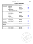
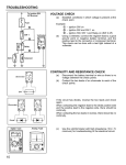
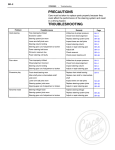
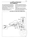
EFI SYSTEM
−
FI−9
Troubleshooting
TROUBLESHOOTING
TROUBLESHOOTING HINTS
1.
CT
JE
O
Engine troubles are usually not caused by the EFI
system.
When troubleshooting, always first check the condition
of the other systems.
(a) Electronic source
•
Battery
•
Fusible links
•
Fuses
(b) Body ground
(e) Fuel supply
•
Fuel leakage
•
Fuel filter
•
Fuel pump
(d) Ignition system
•
Spark plugs
•
High−tension cords
•
Distributor
•
Ignition coil
•
Igniter
(e) Air induction system
•
Vacuum leaks
(f) Emission control system
•
PCV system
•
EGR system
(g) Others
•
Ignition timing (ESA system)
•
Idle speed (ISC system)
•
etc.
2. The most frequent cause of problems is simply a bad
contact in wiring connectors. Always check that
connections are secure.
When inspecting the connector, pay particular attention
K
to the following points:
CISCO IDS PAR
TS
PR
(a) Check to see that the terminals are not bent.
(b) Check to see that the connector is pushed in
completely and locked.
(c) Check to see that there is no signal change when
the connector is slightly tapped or wiggled.
3. Troubleshoot sufficiently for other causes before replacing
the ECU, as the ECU is of high quality and it is expensive.
.CISCOKIDS.C
WW
O
M
W
.A
U
FI−10
EFI SYSTEM
−
Troubleshooting
4. Use a volt/ohmmeter with high impedance (10 kW/V minimum) for troubleshooting of the electrical circuit.
(See page FI−29)
TROUBLESHOOTING PROCEDURES
SYMPTOM − DIFFICULT TO START OR NO START
(ENGINE WILL NOT CRANK OR CRANKS SLOWLY)
CHECK ELECTRIC SOURCE
BAD
CHECK STARTING SYSTEM
BAD
1. Battery
(1) Connection
(2) Gravity − Drive belt − Charging system
(3) Voltage
2. Fusible links
1. Ignition switch
2. Starter relay (USA only)
3. Starter
4. Neutral start switch
5. Wiring/Connection
SYMPTOM − DIFFICULT TO START OR NO START (CRANKS OK)
CHECK DIAGNOSIS SYSTEM
Check for output of diagnostic code.
(See page FI−22)
Malfunction
code(s)
Diagnostic code(s)
(See page FI−26)
Normal code
DOES ENGINE START WITH
ACCELERATOR PEDAL
DEPRESSED?
YES
BAD
CHECK IGNITION SPARK
(See page IG−5)
BAD
1. Oil filler cap
K
CISCO IDS PAR
TS
2. Oil dipstick
PR
3. Hose connections
4. PCV hoses
5. EGR system − EGR valve stays open
CT
JE
O
CHECK FOR VACUUM LEAKS IN AIR
INTAKE LINE
ISC system
(1) ISC valve
(2) Wiring connection
.CISCOKIDS.C
WW
O
M
W
.A
U
CONTINUED ON PAGE FI−11
1. High−tension cords
2. Distributor
3. Ignition coil
4. Igniter
EFI SYSTEM
# OK
−
FI−11
Troubleshooting
CONTINUED FROM PAGE FI−10
1. Spark plugs
2. Compression pressure
Minimum: 9.0 kg/cm2
(128 psi, 883 kPa)
at 250 rpm
3. Valve clearance
Standard: IN 0.15 − 0.25 mm
(0.006 − 0.010 in.)
EX 0.20 − 0.30 mm
(0.008 − 0.012 in.)
CHECK SPARK PLUGS
Plug gap: 1.1 mm (0.043 in.)
HINT: Check compression pressure
and valve clearance if necessary.
BAD
All
Plugs
WET)
CHECK FUEL SUPPLY TO INJECTOR
1. Fuel in tank
2. Fuel pressure in fuel line
(1) Connect terminals + B and FP of the
check connector.
(2) Fuel pressure at fuel return hose can
be felt. (See page FI−49)
CHECK FUEL PUMP SWITCH IN AIR
FLOW METER
Check continuity between terminals FC
and E1 while measuring plate of air
flow meter is open.
BAD
1. Injector(s) − Shorted or leaking
2. Injector wiring − Short circuited
3. Cold start injector − Leakage
(See page FI−54)
4. Cold start injector time switch
(See page FI−78)
1. Fuel line − Leakage − Deformation
2. Fuse
3. Fuel pump (See page FI−48)
4. Fuel filter
5. Fuel pressure regulator (See page FI−57)
Air flow meter (See page FI−66)
BAD
Ignition timing − Adjust (See page IG−12)
CHECK IGNITION TIMING
1. Connect terminals TE1 and E1 of the
check connector.
2. Check ignition timing.
Standard: 10_ BTDC @ idle
(w/ Terminals TE1 and E1 connected)
.CISCOKIDS.C
WW
O
M
W
.A
U
BAD
1. Wiring connection
2. Power to ECU
(1) Fusible links
(2) Fuses
(3) EFI main relay (See page FI−76)
3. Air flow meter (See page FI−66)
4. Water temp. sensor (See page FI−79)
5. Air temp. sensor (See page FI−66)
6. Injection signal circuit
(1) Injector wiring
(2) ECU (See page FI−85)
PR
CT
JE
O
CHECK EFI ELECTRONIC CIRCUIT
USING VOLT/OHMMETER
(See page FI−29)
K
CISCO IDS PAR
TS
FI−12
EFI SYSTEM
−
Troubleshooting
SYMPTOM − ENGINE OFTEN STALLS
CHECK DIAGNOSIS SYSTEM
Check for output of diagnostic code.
(See page FI−22)
Malfunction
code(s)
Diagnostic code(s) (See page FI−26)
Normal code
CHECK FOR VACUUM LEAKS IN AIR
INTAKE LINE
CHECK FUEL SUPPLY TO INJECTOR
1. Fuel in tank
2. Fuel pressure in fuel line
(1) Connect terminals + Band FP
of the check connector.
(2) Fuel pressure at fuel return hose
can be felt. (See page FI−49)
CHECK AIR FILTER ELEMENT
CHECK IDLE SPEED
Standard: 700 rpm
BAD
BAD
BAD
BAD
1. Oil filler cap
2. Oil dipstick
3. Hose connections
4. PCV hoses
5. EGR system − EGR valve stays open
1. Fuel line − Leakage − Deformation
2. Fuses
3. Fuel pump (See page FI−48)
4. Fuel filter
5. Fuel pressure regulator (See page FI−57)
Element − Clean or replace
ISC system
(1) Wiring connections
(2) ISC valve (See page FI−73)
(3) ECU (Test by substitution)
Ignition timing − Adjust (See page IG−12)
CHECK SPARK PLUGS
Plug gap: 1.1 mm (0.043 in.)
HINT: Check compression pressure
and valve clearance if necessary.
1. Spark plugs
2. Compression pressure
Minimum: 9.0 kg/cm@
(128 psi, 883 kPa)
K
CISCO IDS PAR
at 250 rpm
TS
PR
3. Valve clearance (Cold)
Standard: IN 0.15 − 0.25 mm
(0.006 − 0.010 in.)
EX 0.20 − 0.30 mm
(0.008 − 0.012 in.)
CT
JE
O
CHECK IGNITION TIMING
1. Connect terminals TE1 and E1 of the
service connector.
2. Check ignition timing.
Standard: 10_ BTDC @ idle
(w/ Terminals TE1 and El
connected)
CONTINUED ON PAGE FI−13
.CISCOKIDS.C
WW
O
M
W
.A
U
EFI SYSTEM
−
FI−13
Troubleshooting
CONTINUED FROM PAGE FI−12
CHECK COLD START INJECTOR
(See page FI−54)
BAD
RECHECK FUEL PRESSURE
(See page FI−49 )
BAD
CHECK INJECTORS
(See page FI−59)
BAD
CHECK EFI ELECTRONIC CIRCUIT USING
VOLT/OHMMETER
(See page FI−29)
BAD
1. Cold start injector (See page FI−54)
2. Cold start injector time switch
(See page FI−78)
1. Fuel pump (See page FI−48)
2. Fuel filter
3. Fuel pressure regulator (See page FI−57 )
Injection condition
1. Wiring connections
2. Power to ECU
(1) Fusible links
(2) Fuses
(3) EFI main relay (See page FI−76)
3. Air flow meter (See page FI−66)
4. Water temp. sensor (See page FI−79)
5. Air temp. sensor (See page FI−66)
6. Injection signal circuit
(1) Injector wiring
(2) ECU (See page FI−85)
SYMPTOM ENGINE SOMETIMES STALLS
CHECK DIAGNOSIS SYSTEM
Check for output of diagnostic code.
(See page FI−22)
Malfunction
code(s)
Diagnostic code(s) (See page FI−26)
Normal code
BAD
Air flow meter
K
CISCO IDS PAR
TS
1. Connectors
2. EFI main relay (See page FI−76)
3. Circuit opening relay (See page FI−77)
PR
CT
JE
O
CHECK WIRING CONNECTORS AND
RELAYS
Check for signal change when the
connector or relay is slightly tapped or
wiggled.
BAD
.CISCOKIDS.C
WW
O
M
W
.A
U
CHECK AIR FLOW METER
(See page FI−66)
FI−14
EFI SYSTEM
−
Troubleshooting
SYMPTOM − ROUGH IDLING AND/OR MISSING
CHECK DIAGNOSIS SYSTEM
Check for output of diagnostic code.
(See page FI−22)
Malfunction
code(s)
Diagnostic code(s) (See page FI−26)
Normal code
CHECK FOR VACUUM LEAKS IN AIR
INTAKE LINE
CHECK AIR FILTER ELEMENT
BAD
BAD
1. Oil filler cap
2. Oil dipstick
3. Hose connections
4. PCV hoses
5. EGR system − EGR valve stays open
Element − Clean or replace
CHECK IDLE SPEED
STD: 700 rpm
ISC system
(1) Wiring connections
(2) ISC valve (See page FI−73)
(3) ECU
CHECK IGNITION TIMING
1. Connect terminals TE1 and E1 of the
check connector.
2. Check ignition timing.
Standard: 10_ BTDC @ idle
(w/ Terminals TE1 and
E1 connected)
Ignition timing − Adjust (See page IG−12)
CHECK SPARK PLUGS
Plug gap: 1.1 mm (0.043 in.)
HINT: Check compression pressure and
valve clearance if necessary.
1 . Spark plugs and high−tension cords
2. Compression pressure
Minimum: 9.0 kg/cm@
(128 psi, 883 kPa)
at 250 rpm
3. Valve clearance (Cold)
Standard: IN
0.15 − 0.25 mm
(0.006 − 0.010 in.)
EX
0.20 − 0.30 mm
(0.008 − 0.012 in.)
CHECK COLD START INJECTOR
(See page FI−54)
BAD
CT
JE
O
K
CISCO IDS PAR
1. Cold start injector (See page FI−54)
TS
PR
2. Cold start injector time switch.
(See page FI−78)
CONTINUED ON PAGE FI−15
.CISCOKIDS.C
WW
O
M
W
.A
U
EFI SYSTEM
−
FI−15
Troubleshooting
CONTINUED FROM PAGE FI−14
BAD
CHECK INJECTORS
(See page FI−59)
BAD
CHECK EFI ELECTRONIC CIRCUIT
USING VOLT/OHMMETER
(See page FI−29)
BAD
1. Fuel pump (See page FI−48)
2. Fuel filter
3. Fuel pressure regulator (See page FI−57)
Injection condition
1. Wiring connections
2. Power to ECU
(1) Fusible links
(2) Fuses
(3) EFI main relay (See page FI−76)
3. Air flow meter (See page FI−66)
4. Water temp. sensor (See page FI−79)
5. Air temp. sensor (See page FI−66)
6. Injection signal circuit
(1) Injector wiring
(2) ECU (See page FI−85)
7. Oxygen sensor(s) (See pages FI−82, 84)
K
CISCO IDS PAR
TS
PR
CT
JE
O
.CISCOKIDS.C
WW
O
M
W
.A
U
CHECK FUEL PRESSURE
(See page FI−49)
FI−16
EFI SYSTEM
−
Troubleshooting
SYMPTOM − HIGH ENGINE IDLE SPEED (NO DROP)
CHECK ACCELERATOR LINKAGE
CHECK DIAGNOSIS SYSTEM
Check for− output of diagnostic code.
(See page R−22)
BAD
Malfunction
code(s)
Linkage − Stuck
Diagnostic code(s) (See page FI−26)
Normal code
BAD
CHECK THROTTLE POSITION
SENSOR (See page FI−68)
BAD
CHECK FUEL PRESSURE
(See page FI−49)
BAD
CHECK COLD START INJECTOR
(See page FI−54)
BAD
CHECK INJECTORS (See page FI−59)
CHECK EFI ELECTRONIC CIRCUIT
USING VOLT/OHMMETER
(See page FI−29)
BAD
BAD
1. Wiring connections
2. ISC valve (See page FI−72)
3. Air conditioner switch
Throttle body
Fuel pressure regulator − High pressure
Cold start injector − Linkage
Injectors − Leakage, Injection quantity
1. Wiring connection
2. Power to ECU
(1) Fusible links
(2) Fuses
(3) EFI main relay (See page FI−76)
3. Air flow meter (See page FI−66)
4. Water temp. sensor (See page FI−79)
5. Air temp. sensor (See page FI−66)
6. Injector signal circuit
(1) Injector wiring
(2) ECU (See page FI−85)
K
CISCO IDS PAR
TS
PR
CT
JE
O
.CISCOKIDS.C
WW
O
M
W
.A
U
CHECK ISC SYSTEM
EFI SYSTEM
−
FI−17
Troubleshooting
SYMPTOM − ENGINE BACKFIRES−Lean Fuel Mixture−Misfire
CHECK DIAGNOSIS SYSTEM
Check for output of diagnostic code.
(See page FI−22)
Malfunction
code(s)
Diagnostic code(s) (See page FI−26)
Normal code
BAD
Ignition timing − Adjust (See page IG−12)
CHECK IGNITION TIMING
1. Connect terminals TE1 and E1 of
the check connector.
2. Check ignition timing.
Standard: 10_ BTDC @ idle
(w/ Terminals TE1 and
E1 connected)
CHECK COLD START INJECTOR
(See page FI−54)
BAD
CHECK FUEL PRESSURE
(See page FI−49)
BAD
CHECK INJECTORS
(See page FI−59)
BAD
CHECK EFI ELECTRONIC CIRCUIT
USING VOLT/OHMMETER
(See page FI−29)
1. Oil filler cap
2. Oil dipstick
3. Hose connections
4. PCV hose(s)
5. EGR system − EGR valve stays open
BAD
1. Cold start injector (See page FI−54)
2. Cold start injector time switch
(See page FI−78)
1. Fuel pump (See page FI−48)
2. Fuel filter
3. Fuel pressure regulator (See page FI−57)
Injectors − Clogged
CT
JE
O
1. Wiring connection
2. Power to ECU
(1) Fusible links
(2) Fuses
(3) EFI main relay (See page FI−76)
3. Air flow meter (See page FI−66)
4. Water temp. sensor (See page FI−79)
K
5. Air temp. sensor (See page FI−66)
CISCO IDS PAR
TS
6. Throttle position sensor (See page FI−68)
PR
7. Injection signal circuit
(1) Injector wiring
(2) Fuel cut RPM (See page FI−88)
(3) ECU (See page FI−85)
8. Oxygen sensor(s) (See pages FI−82, 84)
.CISCOKIDS.C
WW
O
M
W
.A
U
CHECK FOR VACUUM LEAKS IN AIR
INTAKE LINE
FI−18
EFI SYSTEM
−
Troubleshooting
SYMPTOM − MUFFLER EXPLOSION (AFTER FIRE)−Rich Fuel Mixture−Misfire
CHECK DIAGNOSIS SYSTEM
Check for output of diagnostic code.
(See page FI−22)
Malfunction
code(s)
Diagnostic code(s) (See page FI−26)
Normal code
CHECK IGNITION TIMING
1. Connect terminals TE1 and E1 of the
check connector.
2. Check ignition timing.
Standard: 10_ BTDC @ idle
(w/ Terminals TE1 and E1
connected)
Ignition timing − Adjust (See page IG−12 )
CHECK COLD START INJECTOR
(See page FI−54)
BAD
CHECK FUEL PRESSURE
(See page FI−49)
BAD
BAD
Injectors − Leakage
1. Spark plugs
2. Compression pressure
Minimum: 9.0 kg /cm2
(128 psi, 883 kPa)
at 250 rpm
3. Valve clearance (cold)
Standard:
IN
0.15 − 0.25 mm
(0.006 − 0.010 in.)
EX 0.20 − 0.30 mm
(0.008 − 0.012 in.)
CHECK SPARK PLUGS
Plug gap: 1.1 mm (0.043 in.)
HINT: Check compression pressure and
valve clearance if necessary.
CHECK EFI ELECTRONIC CIRCUIT
USING VOLT/OHMMETER
(See page FI−29)
Fuel pressure regulator (See page FI−57)
BAD
1. Throttle position sensor
2. Injection signal circuit
(1) Injector wiring
(2) Fuel cut RPM (See page FI−88)
SCOKIDS PA
(3) ECU (See page FI−85) CI
RT
S
PR
3. Oxygen sensor(s) (See pages FI−82, 84)
CT
JE
O
.CISCOKIDS.C
WW
O
M
W
.A
U
CHECK INJECTORS (See page FI−59)
1. Cold start injector (See page FI−54)
2. Cold start injector time switch
(See page FI−78)
EFI SYSTEM
−
FI−19
Troubleshooting
SYMPTOM − ENGINE HESITATES AND/OR POOR ACCELERATION
CHECK BRAKES
BAD
CHECK FOR VACUUM LEAKS 1N AIR
INTAKE LINE
BAD
CHECK AIR FILTER ELEMENT
CHECK DIAGNOSIS SYSTEM
Check for output of diagnostic code.
(See page FI−22)
BAD
Malfunction
code(s)
Brakes − Drag
1. Oil filler cap
2. Oil dipstick
3. Hose connections
4. PCV hose(s)
5. EGR system − EGR valve stays open
Element − Clean or replace
Diagnostic code(s) (See page FI−26)
Normal code
CHECK IGNITION SPARK
(See page IG−5)
BAD
1. High−tension cords
2. Distributor
3. Ignition coil
4. Igniter
Ignition timing − Adjust (See page IG−12)
CHECK IGNITION TIMING
1. Connect terminals TE1 and E1 of the
check connector.
2. Check ignition timing
Standard: 10_ BTDC @ idle
(w/ Terminals TE1 and E1
connected)
CHECK FUEL PRESSURE
(See page FI−49 )
BAD
CHECK INJECTORS
(See page FI−59)
BAD
1. Fuel pump (See page FI−48)
2. Fuel filter
3. Fuel pressure regulator (See page FI−57)
Injection condition
CONTINUED ON PAGE FI−20
K
CISCO IDS PAR
TS
PR
CT
JE
O
.CISCOKIDS.C
WW
O
M
W
.A
U
FI−20
EFI SYSTEM
−
Troubleshooting
CONTINUED FROM PAGE FI−19
CHECK SPARK PLUGS
Plug gap: 1.1 mm (0.043 in.)
HINT: Check compression pressure and
valve clearance if necessary.
BAD
1. Wiring connections
2. Power to ECU
(1) Fusible links
(2) Fuses
(3) EFI main relay (See page FI−76)
3. Air flow meter (See page FI−66)
4. Water temp. sensor (See page FI−79)
5. Air temp. sensor (See page FI−66)
6. Throttle position sensor (See page FI−68)
7. Injection signal circuit
(1) Injector wiring
(2) ECU (See page FI−85)
K
CISCO IDS PAR
TS
PR
CT
JE
O
.CISCOKIDS.C
WW
O
M
W
.A
U
CHECK EFI ELECTRONIC CIRCUIT
USING VOLT/OHMMETER
(See page FI−29)
1. Spark plugs
2. Compression pressure
Minimum: 9.0 kg /cm2
0 28 psi, 883 kPa f
at 250 rpm
3. Valve clearance (Cold)
Standard: IN 0.15 − 0.25 mm
(0.006 − 0.010 in.)
EX 0.20 − 0.30 mm
(0.008 − 0.012 in.)