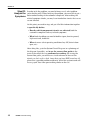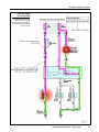
1
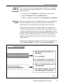
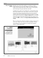
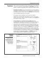
Section 4
Six-Step Troubleshooting Plan
Learning Objectives:
1. Introduce the six−step troubleshooting process.
2. Explain what needs to be done when verifying a problem.
3. Explain all the components of a related symptoms check.
4. Using the circuit tracing technique, show how to analyze the
symptoms and define the problem you need to diagnose.
5. Show how to use the EWD when isolating a problem.
6. Explain repair techniques for wires, terminals, and connectors.
7. Perform a practice case study on the Lexus Body Electrical
Simulator using the six−step approach.
Body Electrical Diagnosis - Course L652
1
Section 4
2
LEXUS Technical Training
Six-Step Troubleshooting Plan
Introduction
You have now covered all of the tools" used when diagnosing electrical
problems:
• Basic electrical concepts
• Use of the EWD
• Tracing current flow through a system circuit diagram
• Use of the DVOM & jumper wires
Now it’s time to put all of these components together to diagnose
electrical problems.
The Diagnostic
Process
It would be great if we could just walk up to a vehicle and instinctively
know where an electrical problem was, and what exactly had to be
done to repair it. This happens occasionally when fixing a problem that
you have seen a number of times on a particular model. Your
experience from repeatedly fixing this problem allows you to make the
repairs quickly, with no wasted effort.
But what about problems that you see on only an occasional basis,
where there is no trend" of past failures to help you? To diagnose these
types of problems in the least amount of time, you need to make your
diagnosis following a six−step troubleshooting plan.
Six-Step
Troubleshooting
Plan
In L623, the Six−Step Troubleshooting Plan was introduced. These
steps are:
1. Verify the complaint
2. Determine the related symptoms
3. Analyze the symptoms
4. Isolate the trouble
5. Correct the trouble
6. Check for proper operation
By using this troubleshooting plan, you can minimize the amount of time
spent diagnosing the circuit by performing only the checks that you need
to make, with an emphasis on checks that are the easiest to make.
Quickly finding and fixing an electrical problem doesn’t depend on
luck, but on your skills: applying what you know about circuits, using
the EWD, and devising a strategy to isolate the location of the problem.
The six−step approach is a way to organize your efforts, keeping you
on−track while you are troubleshooting the problem.
Body Electrical Diagnosis - Course L652
3
Section 4
Six-Step Troubleshooting Plan
4
LEXUS Technical Training
Six-Step Troubleshooting Plan
Step #1:
Verify the
Complaint
This is the first step in any diagnostic process. When you are handed a
repair order with a customer’s complaint on it, there are three things
that you must do:
1. You must be able to identify the problem the customer noted
2. You must determine if it is a problem or not
3. If there is a problem, determine if it is intermittent or continuous
Identify the The average customer is not a technically oriented" person. When they
Problem describe a problem, it’s not always going to be easy to understand
them, especially if you weren’t the person who wrote it on the RO.
Your knowledge about how each system works is very important in
recognizing what the customer is talking about. If you don’t know how
a system is supposed to operate when it’s OK, you won’t know when it
is broken. Because of the number of systems/circuits on the vehicle and
the increased use of ECU−type controls in them, it is becoming more
difficult to keep up with the details on how all the systems, model to
model, operate.
The best places to look for information on how a system should operate
are the System Outline in the EWD and the Owner’s Manual.
Verify the Complaint
Body Electrical Diagnosis - Course L652
5
Section 4
Does a Problem Sometimes what seems like a problem to a customer is actually a
Exist? normal function of the circuit. For example, the customer complaint
could be about the power door locks: When the key is in the ignition,
with the door open, the power door locks won’t lock."
A condition such as this is not a problem, but a normal function of the
Power Door Lock ECU and its key confine" feature which is designed
to prevent the customer from locking their keys in the car. For the
customer, information about the operation on all the electrical systems
on the vehicle can be found in the Owner’s Manual. For you, detailed
information about the operation of different electrical systems can be
found in the EWD, as well as in the Repair Manual Body Electrical
section.
There are also instances where the customer is noticing a characteristic
of the vehicle. There are no fixes" for these non−problems. The best
way to identify this type of condition is to compare the customer’s
vehicle to a known good vehicle.
Use the
Owner’s Manual
as a Reference
Like the EWD system
outline, the Owner’s
Manual is a good resource
for information on how
different systems or circuits
are supposed to operate.
6
LEXUS Technical Training
Six-Step Troubleshooting Plan
Intermittent or When verifying the problem, you must also determine if the problem is
Continuous? continuous or intermittent. If the problem is continuous (or not inter−
mittent), it should be fairly obvious when you operate the suspect system.
Intermittent problems can be more difficult to find. If the problem is
intermittent, you’ll need to know as much information as possible (from
the ASM or customer directly) about the conditions that were present
when the problem occurred for the customer.
For example, electrical problems can be triggered by ambient
temperature, vibrations from road conditions, weather, or the type of
driving (only on turns, hills, etc.) How the customer actually operates
the system can also be a factor.
If the conditions are repeated and the problem does not
re−occur, make a thorough visual inspection of the harness, connectors,
and terminals, with attention to the terminal spread. Simulate the
vibrations that are caused during driving by wiggling" harnesses and
connectors. Keep in mind that as you move the harnesses or disconnect
connectors, you may cause the problem to temporarily fix" itself. While
making your inspections, try to minimize these changes" to the circuit,
and keep track of which harnesses or connectors you have disconnected
or moved. Although it will be difficult in some cases, be sure to identify
exactly what is causing the problem, and NEVER consider the
vehicle’s problem solved if it happens to magically fix itself".
Intermittent
Problem
Simulation
Try to simulate the
conditions under which
the problem occurred. The
ES 300 Repair Manual, has
a Troubleshooting Section
which was introduced
to assist in diagnosing
problems with ECU
controlled systems.
Body Electrical Diagnosis - Course L652
7
Section 4
In general, you cannot make an accurate diagnosis or repair of a
problem you cannot duplicate. If the situation warrants it, call
Technical Assistance to see if there have been any other reported
cases of the problem or for advice on how to proceed with the vehicle.
Step #2:
Determine
the Related
Symptoms
Now that you have verified that there is a problem, you need to
examine the problem symptoms more thoroughly. The related
symptoms check is basically an operational check, so you won’t
need any tools except for the EWD. The major goal of this check is to
determine:
1. How much of the circuit is affected.
2. Find clues to the location of the problem by operating other
circuits related or connected to the problem area.
To say determine the related symptoms" sounds complex, but this is
one of the most important and time saving steps you can make in the
diagnostic process.
How a Circuit is In this step, you need to operate the problem circuit thoroughly, noting
“Related” exactly what is and what is not working. Based upon your
observations, make checks to the related circuits. Circuits are related
to another circuit because of a parallel connection:
• Most electrical circuits consist of two or more loads that are
connected in parallel.
• Entirely different circuits are related to another circuit by a parallel
connection to common power sources (fuses) or ground
points.
• Shared sensor or switch functions in which a single switch
operates a number of different circuits (such as the LH front door
courtesy switch operating both the interior lighting and key
warning buzzer circuits).
8
LEXUS Technical Training
Six-Step Troubleshooting Plan
How Circuits
are Related
Circuits are related
through shared fuse/power
connections, and through
splices on the +B or ground
side of the component.
Body Electrical Diagnosis - Course L652
9
Section 4
How Much of In order to know what loads or other circuits are related, you’ll need to
the Circuit is look in the EWD System Circuit Diagram. The wiring diagram will tell
Affected? you what loads are connected in a particular circuit, and how they are
switched. Section H Power Source (Current Flow Chart), as well as the
power source system diagram, will give you +B side" circuit
information. For ground point information, Section J diagrams all of
the splices on the ground side of the circuits.
By checking the operation of related circuits, you will be eliminating
parts of the circuit or components as the possible problem causes. With
fewer items that need to be checked, you’ll spend less time isolating the
location of the problem.
While operating the circuit, you need to determine if the problem
affects all of the circuit or just part of it. Based upon how the circuit
operates, you can make some assumptions:
If Entire Circuit is If the entire circuit system is dead", this indicates that:
Inoperative
• There is a possible problem with a power (fuse) or ground circuit.
• The load or component is bad.
There are a large number of problems that could cause a component
not to work, from an open power wire or ground wire, to a simple bad
component. Because of this, you need a place to start your inspection.
To begin, the easiest inspection to make would be to check the power
and ground of the component by operating related circuits. By
using the EWD, making a quick check of both power and ground is
simple:
• Checking Power: Look at the system circuit diagram and Section
H, Power Source Current Flow Chart to determine other circuits
which share the fuse and check their operation. Even if the fuse is
not shared by another circuit, simply locating and inspecting the
fuse can be done quickly.
• Checking Ground: Operating a shared" circuit also provides a
quick check of the ground circuit. By using the Section J, Ground
Point information in the EWD, you can find out if another circuit
uses the same ground point. If a circuit which shares the ground
works OK, you’ll know that the ground point is OK.
Neither of these checks isolates the exact location of the circuit
problem. But they can quickly point to the areas you need to check and
save you from making a lot of unnecessary inspections.
10
LEXUS Technical Training
Six-Step Troubleshooting Plan
Check for
Possible Fuse or
Ground Problem
If the whole circuit is
inoperative, operate another
circuit which uses the same
fuse. Then operate another
circuit that uses the same
ground point.
Body Electrical Diagnosis - Course L652
11
Section 4
If Any Part of the If any part of the circuit still works:
Circuit Works
• You know that the power to the circuit and the main ground point
are probably OK.
• You need to find out exactly which loads are working and which are
not. This will let you look for common wiring or connections
between the bad" parts of the circuit.
If any part of the problem circuit works, it is extremely important to
determine exactly which parts are working and which parts
are not. This step will save you from making unnecessary checks to
parts of the circuit that are OK.
For example, the customer complaint is that the stop lights do not
work. As you step on the brake, you notice that the high mount stop
light works. Knowing this verifies that a large portion of the circuit is
OK. By eliminating parts of the circuit that are OK, the number of
places you need to check is reduced. This is what checking the related
symptoms is all about.
12
LEXUS Technical Training
Six-Step Troubleshooting Plan
Eliminate Parts
of the Circuit
If one or more of the stop
lights work, you know that
the fuse , the grounds, and
part of the wiring are OK.
Body Electrical Diagnosis - Course L652
13
Section 4
Circuits with When working on a system that has self−diagnostic capability, the
Self-Diagnostics New Car Features (NCF) book and the Repair Manual (RM) are
the only places to find information about how to access the Diagnostic
Trouble Codes, and what each individual code means. The RM also
contains specific diagnostic procedures for each circuit, including a
table to direct you in diagnosing problems that do not set trouble codes.
Because the method for accessing the codes varies from system to
system, you’ll need to turn to the specific RM section for each of these
systems.
In these circuits, the EWD is best used in conjunction with the RM and
NCF. It’s location tables and color wiring diagrams provide a good
supplement to the RM information.
Use the
Repair Manual
for Systems with
Self-Diagnostics
The RM is the first place
to look when working with
these systems. The EWD is
helpful, especially with the
color wiring diagrams, and
location information.
14
LEXUS Technical Training
Six-Step Troubleshooting Plan
Diagnosing If the circuit has an ECU with self−diagnostic ability, the general
with DTCs diagnostic strategy is to:
1. Always check for Diagnostic Trouble Codes (DTC) first, and
write them down. Point any Freeze Frame data for reference.
2. Clear the code memory and operate the system/vehicle to see if the
problem is intermittent or continuous.
3. If the trouble code(s) reappear, follow the diagnostic tables in the
RM.
4. If there are no codes, but there is a problem present, use the
Problem Symptoms Table in the repair manual to direct you to the
proper inspections.
5. While diagnosing the circuit, use the EWD to help you locate
the components, pins, connectors, or splices.
There are other techniques that you can use depending on the system
you are diagnosing. This additional information on ECU system
diagnosis is covered in L672.
Diagnostic Trouble
Codes (DTCs)
DTCs are used in many
body electrical systems
including Cruise Control,
Anti-lock Brakes, Airbag,
and Engine Control
Systems
Body Electrical Diagnosis - Course L652
15
Section 4
Step #3:
Analyze the
Symptoms
In order to fix the problem, you need to know exactly what problem
you’re dealing with. When verifying the problem, you were able to get a
better understanding of the customer’s complaint. After making the
related symptoms checks, you may have found other circuits that are or
are not affected.
At this point, you need to stop, and put all of this information together
to specifically define:
• Exactly which components/circuits are affected (both the
customer’s complaint and any related symptoms)
• What kind of problem you need to look for (open, short−to−ground,
high resistance, feedback)
• When it occurs (what operating conditions: key ON, driver’s door
open, etc.)
After doing this, go to the System Circuit Diagram (or a photocopy of
the diagram if possible), and trace the current flow paths in the
parts of the circuit that are confirmed as working. By tracing the
current flow paths, you will have a visual reference of areas of the
circuit you don’t need to check. Areas that you have NOT traced are all
places that a possible problem could exist. All of this up−front work will
have a payoff: Less time spent making checks on the car!
16
LEXUS Technical Training
Six-Step Troubleshooting Plan
Trace the Paths
of Current Flow
The shaded areas indicate
where the circuit is OK.
Tracing current flow here is
the same as you did earlier
in the course.
Body Electrical Diagnosis - Course L652
17
Section 4
Step #4:
Isolate the
Problem
To isolate the problem, there are three actions you need to make:
1. Onthewiringdiagram,findtheareasthatarepossibleproblemareas
2. Determine where to begin making the checks
3. Make your inspections.
Find the Possible When analyzing the symptoms in step 4, you traced the paths of
Problem Areas current flow in the parts of the circuit that were good". You’ll now see
sections of the circuit that have NO tracing on it, places where there is
NO confirmed current flow. Anywhere you have not traced current
flow is a potential problem area. If you are working with a
photocopy of the diagram, circle all of the locations where the
problem could possibly be. This gives you a good visual reference as to
the places you’ll potentially need to check.
Where to Begin Since any ONE of these locations you circled could be the cause of the
problem, you’ll need to find a place to start. In general, the order you
should inspect the potential problems is based upon:
• How easy it is to get to the component
• If the inspection can be done visually
• If there is a known history of failures at a particular point
• If multiple components/circuits are inoperative: Start with
parts of the circuit that are common to both (as opposed to looking
for 2 separate problems).
The inspection process involves the use of all of the tools we discussed
in Section 3 (visual, DVOM, or jumper wire). Make a mental plan of at
least the first two initial checks you need to make. If these initial
checks do not find the cause of the problem, they will at least lead you
into making the additional checks to the circuit which will isolate the
problem. Remember that the location of the problem will be in
one of the areas you circled on the wiring diagram.
The Split-Half If the accessibility of the circuit is good, you can also apply the split−half
Method method. Applying the split−half method to the wiring diagram, you would
locate the middle of the bad" part of the circuit. After you find the
connector nearest to that point, you would determine which half (+B side
or ground side) of the circuit is bad" by making an open circuit voltage or
continuity check. Once that is determined, you would go to a connection in
the middle of that bad" section of the circuit, and again determine which
half of the circuit has a problem. You continue to split the problem section
of the circuit in half, until the actual problem is isolated.
18
LEXUS Technical Training
Six-Step Troubleshooting Plan
NOTE
Whether you apply the split−half method to isolate the problem, or
simply follow the System Circuit Schematic, checking the items that
are most accessible first, you are still applying a process of
elimination. And that really is the heart of the diagnostic process.
There are specific techniques that you can use to isolate open circuits,
short−to−grounds, parasitic loads, and high resistance problems. These
techniques will be discussed in Section 5 of this handbook.
Body Electrical Diagnosis - Course L652
19
Section 4
Circle
the Possible
Problem Areas
Since the problem affects
both bulbs, you would
concentrate on the area
that is in parallel to both.
You could still have more
than one problem which
affect each bulb separately,
but the odds would be in
your favor.
20
LEXUS Technical Training
Six-Step Troubleshooting Plan
Where to Start
Your Diagnosis
Use the component
location information in the
EWD to determine where
to make your inspections,
and which is the easiest
to get to.
Body Electrical Diagnosis - Course L652
21
Section 4
Step #5:
Correct the
Trouble
Correcting the trouble is probably the most straightforward step in the
diagnostic process. Making the repair to an electrical problem will
always involve:
• Repair or replacement of a component
• Wiring repair
• Service to a circuit connection
• Connectors
• Terminals
• Ground point
Component
Service Hints
• When disconnecting and replacing components, make sure that the
circuit is off or the battery is disconnected.
• Certain circuits require special handling. The air bag system for
example requires you to disconnect the battery and wait up to 90
seconds before servicing the system. Always refer to the
Repair Manual for special service precautions.
• If the battery needs to be disconnected, write down the customer’s
radio station pre−sets". Reprogram the stations and reset the clock
after reconnecting the battery.
Wire Repair For any wiring, connector, or terminal repair, your best resource is the
Lexus Wire Harness Repair SST (p/n 00002−04201−02). This kit
contains an assortment of replacement terminals, wire, tools, and
supplies that you will need to perform wire harness repairs. Also, the
wire repair manual, provided with the kit, has charts for terminal and
connector ID/part numbers, and complete instructions on how to make
wire, terminal, and connector repairs.
HINT
• Cuts in the insulation should be wrapped with silicon tape
(supplied in the Wire Repair SST) or covered with heat−shrink
tubing. Be sure to overlap the repair by about 1/2 inch on either
side.
• If the damaged wire needs replacement, make sure the same or
larger diameter is used. Also, try to use the same wire color. When
removing the wire insulation, be careful not to break or nick the
wire strands.
• When splicing wires, make sure the circuit is OFF.
22
LEXUS Technical Training
Six-Step Troubleshooting Plan
Wire
Repair Manual
The wire repair manual
contains charts for terminal
and connector ID, and
instructions for making
repairs. The terminals are
listed by component that
they are used with for
easy reference.
Step #6:
Check for
Proper
Operation
After making the repair, you must always verify that the problem was
actually fixed. Operate the circuit as thoroughly as you did when you
first looked at the car, making sure all of the functions and features of
the circuit are working properly. Sometimes, a circuit has multiple
problems which are causing it to be inoperative. This re−check of the
circuit ensures that the customer will be satisfied. A satisfied customer
means that he or she will return to your dealership for service, and tell
their friends about their service experience, too.
For the rest of this course, you will be using a worksheet that
incorporates all of the six steps that we have talked about. Fill these
worksheets in as you go through the diagnostic case studies that you’ll
do on the Simulator as a class or on the cars in the lab when you work
in small groups.
Body Electrical Diagnosis - Course L652
23
Section 4
24
LEXUS Technical Training