1
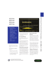
LC334A
LC574A
Datasheet
Leading Specifications
500 MHz and 1 GHz Bandwidth
2 GS/s and 4 GS/s Single- Shot Sample Rate
8 Million Points of Acquisition Memory
4 ms Maximum Sample Rate Window
96 MHz PowerPC Microprocessor
8 to 64 MB System RAM
9" Color Display with 8 Traces
Analog Persistence
Full Screen Grid
Digital oscilloscopes from LeCroy are designed to save engineers valuable time in troubleshooting and problemsolving.
Each oscilloscope is an integrated and powerful system providing the capability to:
Capture the key events with high resolution for longer time intervals
View data like never before, giving you more information more quickly, with a large, color CRT and
advanced display techniques
Analyze your signal to get answers quickly and more accurately with a powerful processing system and
math packages.
Eight trace display for a more complete picture.
9" Color Display
LeCroy provides a very large, sharp oscilloscope screen that is 50% larger in total
viewing area than a 7" screen.
Its powerful features include Analog Persistence, Color-Graded Persistence, Full
Screen mode, Opaque or Transparent display, color association, and personal color
schemes. These provide the user with outstanding benefits that accelerate visual
processing and effective communication of on-screen information.
High-Speed Acquisition
The design and debug of fast digital systems and the need to capture fast transient
signals require high-speed signal capture. The LC574A four-channel, 1 GS/s, 1 GHz
bandwidth DSO operates at a 4 GS/s sample rate for single-channel inputs. The high
sample rate, bandwidth and the 1 GHz trigger bandwidth provide a flexible solution
for capturing and viewing fast risetime signals.
Large Sample Rate Window
Having a high sample rate in a DSO is only the first step to preserving data integrity.
The time window over which this sample rate is available is also of critical
importance. Long acquisition memory maintains the oscilloscope's highest sample
rate for large time windows allowing the user to sample long signals with high
horizontal resolution.
With up to 8 million points of acquisition memory, the maximum sample rate of the
LC574AL of 4 GS/s (2 GS/s in LC334AL) is maintained for a time window of 2 ms (4
ms in LC334AL). This sample rate window enables the user to record long signals
with high resolution.
Optimum Performance
SMARTMemory is a total memory management system that dynamically allocates
resources of microprocessor power, acquisition memory and processing RAM. The
intelligent management provided by SMARTMemory guarantees optimal usage of
oscilloscope resources.
The 96 MHz PowerPC microprocessor at the heart of these DSOs drives the system to
produce results fast, providing rapid waveform update and super panel
responsiveness.
Quick Diagnoses
Capturing and viewing waveforms are fundamental to an oscilloscope. Productivity
improvements are accessible by using built-in math functions to assist
troubleshooting and diagnoses of circuit problems.
The signal analysis capability of these DSOs is enhanced by advanced waveform
math, spectrum analysis, and waveform parameter analysis. This analysis capability
greatly increases the speed with which circuit problems are clearly identified and
solved.
Analog Persistence
At a push of the green button, the user can switch between an analog style view and
a digital view of signals on these oscilloscopes.
The depth of signal information can be explored along the third dimension of the
waveform display to give the user a complete picture of waveform activity.
Unlike an analog oscilloscope, all signal data is captured and available in memory for
analysis and measurements. Analog Persistence gives the user the best of both the
analog and digital worlds of oscilloscopes.
Full Screen Grid
LeCroy DSOs not only have a very large 9" screen but also provide a display mode
with an extra-large grid, up to 150% larger than common grid areas. In Full Screen
mode, all of the screen area is used to display signals. This provides a magnificent
view of up to 8 waveforms: signal details are seen more clearly and with greater
ease.
8-Trace Display
An 8-trace display with any combination of math functions, zooms, reference
memories, or channels is a standard feature in the LC series.
Octal grid display is available in normal and Full Screen display modes, with and
without parameters displayed.
Easy Documentation
All waveform data and results of analysis can be quickly saved to floppy disk,
memory card, ATA flash card, or a removable hard disk. This provides an efficient
way to archive information and facilitates easy documentation of results.
An internal graphics printer (standard in "L" models) outputs screen dumps in
seconds providing the user with an immediate and clear record of signal activity.
Signal Capture
Acquisition System
LC334A Bandwidth (-3 dB): @ 50 ohm: DC to 500 MHz
LC574A Bandwidth (-3 dB): @ 50 ohm: DC to 1 GHz
Bandwidth (-3 dB): @ 1 Mohm: DC to 500 MHz typical at probe tip with optional 1
GHz FET probe for LC334A and with PP005 standard with LC374A and LC574A.
No. of Channels: 4
No. of Digitizers: 4
Max. Sample Rate Window:
4 ms @ 2 GS/s in single-shot mode; LC334AL.
2 ms @ 4 GS/s; LC574AL.
Sensitivity LC334A:
2 mV/div to 5 V/div, 50 ohm, fully variable.
2 mV/div to 5 V/div, 1 Mohm, fully variable.
Sensitivity LC574A:
2 mV/div to 1 V/div, 50 ohm, fully variable.
2 mV/div to 10 V/div, 1 Mohm, fully variable.
Scale factors: A wide choice of probe attenuation factors are selectable.
Offset Range LC334A:
2.00 - 9.99 mV/div: ±120 mV
10.0 - 199 mV/div: ±1.2 V
0.2 - 5.0 V/div: ±24 V
Offset Range LC574A:
2.00 - 4.99 mV/div: ±400 mV
5.00- 99 mV/div: ±1 V
0.1 - 1.0 V/div: ±10 V
1.0 - 10 V/div: ±100 V
(1 Mohm only)
DC Accuracy: Typical 1%
Vertical Resolution: 8 bits
Bandwidth Limiter LC334A: 30 MHz
Bandwidth Limiter LC574A: 25 MHz, 200 MHz
Input Coupling: AC, DC, GND
Input Impedance: 10 Mohm//15 pF for LC334A (system capacitance using PP005),
10 Mohm//11 pF for LC374A/LC574A (system capacitance using PP005) or 50 ohm
±1%.
Max Input:
50 ohm: ±5 V DC (500 mW) or 5 V RMS
1 Mohm on LC334A: 250 V
1 Mohm on LC574A: 400 V (DC + peak AC <=10 kHz)
SMARTMemory: This total memory management system dynamically manages
acquisition memory to guarantee that signals are always sampled at the highest
possible sample rate and that system RAM and microprocessor resources are always
optimally employed.
Acquisition Modes
Random Interleaved Sampling (RIS): For repetitive signals from 1 ns/div to 5
µs/div (2 µs/div for LC574A).
Single shot: For transient and repetitive signals from 10 ns/div (1 ns/div for
LC574A) with all channels active.
Peak detect: At 400 MS/s, peak detect can capture high-speed events down to 1
ns, while simultaneously capturing normally sampled data.
Sequence: Stores multiple events - each of them time stamped - in segmented
acquisition memories.
Dead Time between segments: Typically <30 µs, max. 50 µs
Timebase System
Timebases: Main and up to 4 Zoom Traces
Time/Div Range: 1 ns/div to 1,000 s/div.
Clock Accuracy: <=10 ppm
Interpolator resolution: 10 ps
Roll Mode: Ranges 500 ms to 1,000 s/div. For >50 kpoints: 10 s to 1,000 s/div.
External Clock: <=100 MHz (20-100 MHz for LC574A and LC374A) on EXT input
with ECL, TTL or zero crossing levels. Optional 50 MHz to 500 MHz rear-panel fixed
frequency clock input.
External Reference: Optional 10 MHz rear-panel input.
Additional Information
Interfacing
Remote Control: Possible by GPIB and RS-232-C for all front-panel controls, as well
as all internal functions.
RS-232-C Port: Asynchronous up to 115.2 Kb/s for computer/terminal control or
printer/plotter connection.
GPIB Port: Configurable as talker/listener for computer control and fast data
transfer, up to 300 kbytes/sec. Command Language complies with requirements of
IEEE-488.2.
Centronics Port: Hardcopy parallel interface is standard.
PC Card (PCMCIA I/II/III) Ports: For memory cards, ATA compatible flash cards
and removable hard disks - optional.
Floppy Disk: High-density 3.5" floppy disk drive (DOS format) is standard.
VGA Compatible Display: 15-pin D-type VGA compatible connector for external
color display.
Hardcopy: Screen dumps are activated by a front-panel button or via remote
control. TIFF and BMP formats are available for importing to desktop pub-lishing
programs. The following printers and plotters can be used to make hardcopies:
B/W: HP LaserJet, HP DeskJet 500, Epson FX.
Color: HP DeskJet 550C, Epson Stylus, Canon BJC. An optional, internal, highresolution graphics printer is also available for screen dumps; a stripchart output
format with 2 meters per division is also possible.
Output Formats: ASCII waveform out-put is available in seconds, compatible with
spreadsheets, MATLAB, MathCad. Binary output is also available.
General
Auto-calibration ensures specified DC and timing accuracy.
Temperature: 5° to 40°C (41° to 104°F) rated 0° to 50°C (32° to 122°F)
operating.
Humidity: 80% for temperatures up to 31°C decreasing linearly to 50% relative
humidity at 40°C.
Altitude: Up to 2000m (operating), 40°C max.
Power: 90-132 V AC, 180-250 V AC, 45-66 Hz, 400 W.
Battery Backup: Front-panel settings maintained for two years.
Dimensions:
(HWD)10.4" x 15.65" x 17.85" (264 mm x 397 mm x 453 mm)
Weight: 20 kg (44 lbs) net, 28 kg (61.6 lbs) shipping.
Warranty: Three years.
CE Approval: EMC: Conforms to EN50081-1 and EN50082-1.
UL and cUL approved: UL standard: UL 3111-1; cUL Canadian Standard CSA-C22.2
No. 1010. 1-92.
Safety: The oscilloscope has been designed to comply with EN61010-1 Installation
Category (Over-voltage Category) II, Pollution Degree 2.
Signal Viewing
Type: Color 9" Raster Scan CRT, 0.26 mm dot pitch.
Resolution: 640 x 480 points.
Display Area: 170 mm x 125 mm - 50% greater than that of a 7" display.
Controls: Rear-panel presets for position, brightness and contrast. Menu controls for
brightness and color selection.
Grid Styles: Single, Dual, Quad, Octal, XY, Single+XY, Dual+XY, and Full Screen an enlarged view of each grid style.
Graticules: Internally generated; separate intensity control for grids and
waveforms. Selectable blending of grid with displayed traces.
Waveform Style: Dot Join with option-al sample point highlight or Dots only.
Persistence Modes: Color-graded per-sistence and Analog Persistence, infinite or
variable with decay over time. In color-graded persistence, a color spectrum from
red through violet is used to map signal intensity. With Analog Persistence, the
brightness level of a single color denotes signal intensity. Each trace's persistence
data is stored in 64 k levels. Analog Persistence is only available in four channel
mode on LC334A models.
Trace Display: Opaque or transparent mode, with overlap management.
Number of Traces: 8 (any mix of channels, memories or Math functions).
Real-time Clock: Date, hours, minutes, seconds.
External Monitor: Rear-panel 15-pin socket for VGA compatible monitor.
Vertical Zoom: Up to 5x vertical ex-pansion (50x with averaging, up to 40 µV/div
sensitivity).
Horizontal Zoom:
LC334A: Waveforms can be expanded to give 2-2.5 points/division. This allows
zoom factors up to 100,000x for the 'M' models and up to 400,000x for the 'L'
models when channels are combined.
LC574A: Waveforms can be expanded to give 0.4-0.5 points per division. Zoom
factors up to 2,000,000x with all channels combined on the LC574AL.
Triggering System
Modes: Normal, Auto, Single, and Stop.
Sources: CH1, CH2, CH3, CH4, Line, EXT, EXT/10. Slope, Level and Coupling are
unique to each source.
Slope: Positive, Negative.
Coupling: AC, DC, HF, LFREJ, HFREJ
Pre-trigger recording: 0 to 100% of full scale (adjustable in 1% increments).
Post-trigger delay: 0 to 10,000 divisions (adjustable in 0.1 div. increments).
Holdoff by time: 10 ns to 20 s
Holdoff by events: 0 to 99,999,999
Internal Trigger Range: ±5 div
EXT Trigger Max Input LC334A:
10 Mohm//15 pF
(system capacitance using PP005):
50 V (DC + peak AC <=10kHz)
50 ohm ±1%: ±5 V DC (500 mW) or 5 V RMS.
EXT Trigger Max Input LC574A:
10 Mohm//11pF
(system capacitance using PP005):
400 V (DC + peak AC <=10 kHz)
50 ohm ±1%: ±5 V DC (500 mW) or 5 V RMS.
EXT Trigger Range: ±0.5 V (±5 V with Ext/10).
Trigger Timing: Trigger Date and Time are listed in the Memory Status Menu.
Trigger Comparator: Optional ECL rear-panel output. Alternatively, the calibrator
output can provide a trigger output or a Pass/Fail test output.
SMART Trigger Types
Pattern: Trigger on the logic combination of 5 inputs - CH1, CH2, CH3, CH4, and
EXT Trigger, where each source can be defined as High, Low or Don't Care. The
Trigger can be defined as the beginning or end of the specified pattern.
Signal or Pattern Width: Trigger on width between two limits selectable from <2.5
ns to 20 s. Will typically trigger on glitches 1 ns wide.
Signal or Pattern Interval: Trigger on interval between two limits selectable from
10 ns to 20 s.
Dropout: Trigger if the input signal drops out for longer than a time-out from 25 ns
to 20 s.
State/Edge Qualified: Trigger on any source only if a given state (or transition)
has occurred on another source. The delay between these events can be defined as a
number of events on the trigger channel or as a time interval.
TV: Allows selection of both line (up to 1500) and field number (up to 8) for PAL
(SECAM), NTSC or nonstandard video.
Exclusion Trigger: Trigger on inter-mittent faults by specifying the normal width or
period of a signal. The oscillo-scope will trigger only on aberrations which are shorter
or longer than normal.
Autosetup
Pressing Autosetup sets timebase, trigger and sensitivity to display a wide range of
repetitive signals, (Frequency above 50 Hz; Duty Cycle greater than 0.1%).
Autosetup Time: Approximately 2 seconds.
Vertical Find: Automatically sets sensitivity and offset for selected channel.
Probes
One PP005 probe is supplied per channel. DC to 500 MHz typical (350 MHz typical for
LC334A) at probe tip, 500 V max.
Probe calibration: Max 1 V into 1 Mohm, 500 mV into 50 ohm, frequency and
amplitude programmable, pulse or square wave selectable, rise and falltime 1 ns
typical. Alternatively, the calibrator output can provide a trigger output or a Pass/Fail
test output.
Maximum Sample Rate and Acquisition Memories
Maximum Sample
Rate
Memory Per Channel
Channel Use
LC334A
LC574A
LC334A
LC574A
LC334AM
LC574AM
LC334AL
LC574AL
Active
Channels
All
Peak Detect OFF
500 MS/s
1 GS/s
100k
500k
2M
All
Paired Peak Detect OFF
1 GS/s
2 GS/s
250k
1M
4M
Ch 2 & Ch 3
Paired + Adapter Peak Detect
OFF
2 GS/s
4 GS/s
500k
2M
8M
One
All
Peak Detect ON
100 MS/s data +
400 MS/s peaks
50k data
+
50k Peaks
250k data
+
250k peaks
1 M data
+
1 M peaks
All
High performance signal conditioning devices preserve signal content.
Cursor Measurements
Relative Time: A pair of arrow cursors measure time differences and voltage
differences relative to each other.
Relative Voltage: A pair of line cursors measure voltage differences.
Absolute Time: A cross-hair marker measures time relative to the trigger and
voltage with respect to ground.
Absolute Voltage: A reference bar measures voltage with respect to ground.
Automated Measurements
A wide range of pulse parameter measurements are available. These are categorized
for ease of use. The categories include Pulse, Horizontal, and Vertical parameters.
Basic statistical measurements (average, highest, lowest, and standard deviation),
can be made on these parameter values in order to understand their distribution.
Pass/Fail Testing and Waveform Limit testing using masks can be performed. Test
conditions can be expressed as either waveform parameter limits, waveform shape
limits (mask) or a combination of both. Any failure can cause preprogrammed
actions such as Hardcopy, Save, GPIB service request, logic pulse out, audible beep,
or any combination of the above.
Number of segments available
Model
Segments
LC334A
LC574A
500
LC334AM
LC574AM 2,000
LC334AL
LC574AL 2,000
Signal Analysis
A comprehensive and easy-to-use set of diagnostic tools are available. Calculations
are performed rapidly, and results can be presented on-screen or stored to disk.
Rapid Processing System
Microprocessor: 96 MHz PowerPC 603e.
System RAM: 8 to 64 Mbytes.
Video Memory: 1 Mbyte.
Cache Memory: 32 kbyte.
Persistence Data Map Memory: 16 bits per displayed pixel (64 k levels).
Waveform Processing
Up to four processing functions may be performed simultaneously. Standard
functions available are: Add, Subtract, Multiply, Divide, Negate, Identity, Summation
Averaging and Sine x/x. The source information for a math function trace can be
data from an acquisition channel or from another math function trace. This allows
display of traces which "daisy chain" math functions.
Average: Up to 106 averages are possible.
Extrema: Roof, Floor, or Envelope values from 1 to 106 sweeps.
ERES: Six low-pass digital filters provide up to 11-bit vertical resolution. Sampled
data is always available, even when a trace is turned off.
FFT: Spectrum Analysis with five windowing functions and FFT averaging.
Statistical Diagnostics*: The Parameter Analysis package permits in-depth
diagnostics on waveform parameters. Live histogramming of any waveform
parameter measurement is possible and the histogram can be autoscaled to display
the center and width of the distribution.
Any of the above processes can be invoked without losing the data.
*Histogramming and Trending are part of the Parameter Analysis Package.
Internal Memory
Waveform Memory: Up to four 16-bit Memories (M1, M2, M3, M4), whose length
corresponds to the length of the channel acquisition memory.
Zoom & Math Memory: Up to four 16-bit Waveform Processing Memories (A, B, C,
D), whose length corresponds to the length of the channel acquisition memory.
Setup Memory: Four non-volatile memories. The floppy disk or optional memory
cards, Flash card or removable hard disks can also be used for high-capacity
waveform and setup storage.
Precision sampling devices maintain signal integrity in the digital world .System
Memory Configurations
Maximum Horizontal Zoom Factors
Model
Zoom Factors
LC334
4,000x
LC334AM
LC574A
20,000x
LC334AL
LC574AM 100,000x
LC574AL 400,000x
Ordering Information
To request a Quote or Demo on any of the following models,
click here.
Digital Oscilloscopes:
Product
Code
500 MHz, 500 MS/s, 100 kpts./ch, 4 channel Color DSO
LC334A
500 MHz, 500 MS/s, 500 kpts./ch, 4 channel Color DSO
LC334AM
500 MHz, 500 MS/s, 2 Mpts./ch, 4 channel Color DSO
LC334AL
1 GHz, 1 GS/s, 100 kpts./ch, 4 channel Color DSO
LC574A*
1 GHz, 1 GS/s, 500 kpts./ch, 4 channel Color DSO
LC574AM*
1 GHz, 1 GS/s, 2 Mpts./ch, 4 channel Color DSO
LC574AL*
Included with Standard Configuration:
10:1 10 Mohm Passive Probe (1 per channel)
PP005
Operator's Manual
LCXXX-OM
Remote Control Manual
LCXXX-RCM
Hands On Guide
LCXXX-HG
Advanced Waveform Math Package
WP01
Spectrum Analysis Package
WP02
Floppy Disk Drive
FD01
Performance Certificate
Three-Year Warranty
Probes & Accessories:
1 GHz 10:1 FET Probe
AP020
800 MHz 5:1 FET Probe
AP021
2.5 GHz 0.6pF Active Probe
AP022
1 GHz, 10:1, 500 ohm Passive Probe
PP062
ProBus 75 ohm to 50 ohm Adapter
PP090
Software Options:
Parameter Analysis Package (includes Histogramming and Trending)
WP03
Disk Drive Measurements
DDM
Supplementary Disk Drive Measurements
PRML
Optical Recording Measurements
ORM
Hardware Options:
Memory Card Reader and 512k SRAM Card
MC01/04
PCMCIA Type III Slot for Hard Drives and ATA Flash Cards
HD01
PCMCIA Hard Disk 170 Mbyte (requires HD01 option)
HD02
4MB ATA Flash Card (requires HD01 option)
4MBFC
Internal Graphics Printer
GP01**
500 MHz Ext Clock, 10 MHz Ref Input, Trigger Comparator Output
CKTRIG
64 Mbyte System Memory
64MBSM**
Manuals:
Service Manual for LCXXXA
LCXXX-SM
Warranty & Calibration:
US Military Standard
LCXXX-CCMIL
US NIST Standard
LCXXXCCNIST
*
Includes Internal Graphics Printer and Parameter Analysis
Package
**
Included with LC574AL