1
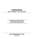
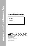
UT200
FREQUENCY-AGILE
HAND-HELD TRANSMITTER
OPERATING INSTRUCTIONS
and trouble-shooting guide
LECTROSONICS, INC.
Rio Rancho, NM
INTRODUCTION
Thank you for selecting the Lectrosonics UT200 hand-held wireless transmitter. The
UT combines over 80 years of engineering experience with the very latest components in a design that addresses the most demanding professional applications.
The design of the UT200 was the direct result of numerous conversations with users,
staging and touring companies and dealers across the US. The specific concerns
and needs brought up in these conversations led directly to the development of the
operational features offered on the UT200. Two hundred fifty six frequencies are user
selectable in 100kHz steps to alleviate interference problems in travelling venues
The UT200 is an integral microphone/transmitter with an internal antenna. The
antenna is a dipole type utilizing the two printed circuit boards as the elements. The
housing is composed of durable PVC, machined to a natural, comfortable shape.
Internal mechanical parts are machined aluminum.
Only the UT200 transmitters are covered in this manual. Companion receivers are
covered in separate manuals. The UT200 will operate with any 200 Series Lectrosonics receiver in the same frequency group.
TABLE OF CONTENTS
INTRODUCTION ................................................................................................... 2
GENERAL TECHNICAL DESCRIPTION ............................................................. 3
CONTROLS AND FUNCTIONS ............................................................................ 5
BATTERY INSTALLATION ..................................................................................... 8
OPERATING INSTRUCTIONS.............................................................................. 9
OPERATING NOTES ............................................................................................. 9
ADJUSTING THE TRANSMITTER FREQUENCY ............................................. 10
TROUBLESHOOTING ......................................................................................... 11
SPECIFICATIONS ............................................................................................... 12
SERVICE AND REPAIR....................................................................................... 13
RETURNING UNITS FOR REPAIR .................................................................... 13
WARRANTY ........................................................................................... Back cover
The UT200 transmitter is FCC type accepted under part 74:
470-608 MHz and 614-806 MHz
UT200 Emission Designator: 180KF3E
2
Frequency Agile Handheld Transmitter
GENERAL TECHNICAL DESCRIPTION
The UT200 transmitters are comprised of a number of functional sub-systems as shown in the block diagram below.
GENERAL
The 200 system uses 75kHz wide deviation for an extremely high signal to noise ratio. The transmitter circuits are all
regulated to allow full output power from the beginning (9 Volts) to the end (7 Volts) of battery life. The input amplifier
uses a Motorola 33078 op amp for ultra low noise operation. It is gain controlled with a wide range input compressor
which cleanly limits input signal peaks over 30dB above full modulation.
DUAL BAND COMPANDOR
Traditionally, compandors have been a source of distortion in wireless microphone systems. The basic problem with
conventional systems is that the attack and decay times are always a compromise. If the time constants are fast, high
frequency transients will not be distorted, but this will cause low frequency distortion. If the time constants are slower,
low frequency audio distortion will be low, but high frequency transients will then be distorted. The 200 system introduces an entirely new approach to solving this basic problem, called “dual-band companding.”
There are actually two separate compandors in the 200 system, one for high frequencies and one for low frequencies.
A crossover network separates the frequency bands at 1kHz with a 6dB per octave slope, followed by separate high
and low frequency compandors. The attack and release times in the high frequency compandor are fast enough to
keep high frequency transient distortion at a low level, and the low frequency compandor uses slower time constants,
reducing low frequency distortion to well below that of a conventional compandor.
NO PRE-EMPHASIS/DE-EMPHASIS
The signal to noise ratio of the 200 system is high enough to preclude the need for conventional pre-emphasis (HF
boost) in the transmitter and de-emphasis (HF roll off) in the receiver. Pre-emphasis and de-emphasis in an FM radio
system usually provides about a 10dB improvement in the signal to noise ratio of the system, but the high frequency
boost in the transmitter must be removed in a purely complementary manner or else the frequency response of the
original audio signal will be altered.
Pre-emphasis can also cause distortion in the receiver. As this signal is passed through the IF filters in the receiver,
distortion can be produced, most noticeably at full modulation. De-emphasis cannot be applied until the signal is
converted into audio, so there is no way around this problem short of eliminating pre-emphasis altogether. Neither of
these problems occur in the 200 system. The dual-band compandor in the 200 Series system essentially provides a
dynamic pre-emphasis/de-emphasis function with extremely low distortion.
PILOT TONE SQUELCH
The 200 system utilizes an ultrasonic tone modulation of the carrier to operate the receiver squelch. This “pilot tone”
consists of a 32kHz signal mixed with the audio signal following the microphone preamp, just after the compandor, to
MIC
ELEMENT
PREAMP
COMPANDOR
INPUT
AMP
LP
FILTER
COMPANDED AUDIO
TO XMTR
AUDIO
LEVEL
Vref
LIMIT
LED
SHUNT
LIMITER
BASS
LP FILTER
TREBLE
HP FILTER
PILOT
TONE
OSC
Vreg
+9VDC
PWR
LED
+5VDC
MUTE
SET
LED
PWR
Vreg
PEAK AUDIO
INDICATOR &
LIMITER
DRIVER
+3.6VDC
PHASE LOCKED LOOP
PRESCALER
COMPANDED
AUDIO
DIVIDER
FREQ
SWITCHES
VOLTAGE
CONTROLLED
OSCILLATOR
LOW PASS
FILTER
TRANSMITTER
Rio Rancho, NM - USA
3
control the audio output muting of the receiver. The pilot tone is filtered out of the audio signal immediately after the
detector in the receiver so that it does not influence the compandor or various gain stages. The basic benefit of the
pilot tone squelch system is that the receiver will remain muted until it receives the pilot tone from the matching
transmitter, even if a strong RF signal is present on the carrier frequency of the system. This is extremely important in
applications such as with an automatic microphone mixer.
WIDE-BAND DEVIATION
75kHz deviation improves the capture ratio, signal to noise ratio and AM rejection of a wireless system dramatically.
Almost all other wireless systems use less than 75kHz deviation.
LONG BATTERY LIFE
High efficiency circuits throughout the design allow over 4 hours of operation using a single 9 Volt alkaline battery (over
12 hours with a new lithium battery.) The battery compartment is a unique mechanical design which automatically
adjusts to fit any brand of alkaline or lithium battery. Battery replacement is easily accomplished by releasing the
bottom and removing the battery cover. The battery contacts are spring loaded to prevent “rattle” as the unit is
handled. The UT200 contains a battery status monitoring circuit which monitors and sends the battery status to the
UDR200B receiver. The battery status is displayed on the front of the receiver.
FREQUENCY AGILITY
The transmitter section uses a synthesized, frequency selectable main oscillator The frequency is extremely stable
over a wide temperature range and over time.
Two rotary switches, located on the side of the unit, provide 256 frequencies in 100kHz steps over a 25.5MHz range.
This alleviates carrier interference problems in mobile or travelling applications.
ANTENNA
The high output antenna utilizes the lower half of the printed circuit boards as one radiating element, with the upper
half of the PC boards and mic capsule as the other half of the dipole configuration. This allows the mic to be held in
any position, since the user’s hands have little or no effect on the radiated power.
MICROPHONE ELEMENT
The UT200 includes the Lectrosonics VariMic mic element. The VariMic is an cardioid condenser back electret microphone that is adapted for the unique circumstances of wireless microphones. The problems it solves are dynamic
range, handling noise and low frequency noise (rumble or wind).
In the VariMic, an unusual pumped source FET circuit increases the usable dynamic range 12dB and greatly reduces
distortion, just as if the FET were being supplied with 48 Volts. In addition, a unique 16 position sensitivity control at the
element itself can adjust the sensitivity in 15 steps over a 15 dB range. This is in addition to the normal gain control in
the wireless microphone. The result is the widest dynamic range of any condenser mic in a wireless microphone.
The VariMic has a three point damped rubber suspension to reduce high frequency handling noise and a generous
sized windscreen to keep wind noise and breath pops away from the microphone.
Low frequency noise is much more of a problem with wireless microphones than with conventional microphones. With
a regular mic, low frequency wind noise, breath thumps or handling rumble can be filtered out at the control board
before the noise causes problems with the following electronics or speaker systems. But with a wireless microphone,
the electronics that will be overdriven are right in the wireless microphone. Filtering at the control board is much too
late. To solve this problem, the VariMic has a low frequency filter that is so sharp that it can remove low frequency
noise without affecting any wanted vocals. It consists of a 36 dB per octave filter circuit to sharply remove low frequency noise below 75 Hz without affecting vocal fundamentals. The lowest operatic bass voice fundamental is 82 Hz.
Isn’t it nice to know that it will come ripping right through.
4
Frequency Agile Handheld Transmitter
CONTROLS AND FUNCTIONS
EXTERNAL
“P” SWITCH – POWER ON/OFF
A slide switch which turns battery power on and off. The LED next to the switch lights up when the “P”
switch is turned on. This LED also serves as a battery condition indicator. The LED will glow brightly
when the battery is good and will dim as the battery condition deteriorates. The LED is at full brightness
with a new battery. When the battery voltage reaches 7 Volts, the LED will be completely dark. Note: this
LED will not light if the EXT LED switch is in the OFF position.
Audio
On/Off
Power
On/Off
A
P
“A” SWITCH – AUDIO ON/OFF
A slide switch which “mutes” the audio in the OFF position and allows the audio gain (modulation level) of the transmitter to be adjusted without feedback from the sound system. This switch will do nothing if the EXTERNAL SWITCHES
switch is in the BYPASS position.
INTERNAL
FREQUENCY ADJUST
Two rotary switches adjust the center frequency of the carrier. The
1.6M is a coarse adjustment and the 100K is the fine adjustment.
Each transmitter is factory aligned at the center of its operating
range. The default position of the frequency select switches is in the
center of the transmitter’s range. See page 10 for details on adjusting the transmitter frequency.
Frequency switches
located behind door.
MOD LEVEL LEDs
These LEDs (loacted under the battery door) indicate the audio input level and are used
when adjusting the transmitter AUDIO LEVEL (gain) control. As the audio level increases,
first one LED lights. The other LED lights as the audio level reaches maximum modulation.
The LEDs are located underneath the battery cover, next to the AUDIO LEVEL control and
are easily viewed when holding the transmitter in a normally used position.
Mod Level
LEDs
AUDIO
LEVEL
Gain Control
AUDIO LEVEL
This knob (also located underneath the battery door) is operated while speaking or singing into the transmitter to
adjust the audio gain of the transmitter for the correct amount of modulation. The LEDs located next to it indicate the
modulation level as the gain is adjusted. See page 6 for details on this very important adjustment.
EXTERNAL SWITCHES BYPASS
This concealed slide switch defeats the external switches on the bottom panel for applications where it is best that the user not be able to operate the power and mute switches. The
external switches are bypassed when this switch handle is moved toward the bottom of the
unit.
Bypass Switches
EXTERNAL
SWITCHES
BYPASS
EXTERNAL
LED
OFF
EXTERNAL LED OFF
This slide switch defeats the battery status LED on the bottom panel for applications where
the LED may be distracting. With this switch in the right-hand position, the power will remain
on and the transmitter operating, even though the power LED is off. The external LED is
disabled when this switch handle is moved toward the bottom of the unit.
Rio Rancho, NM - USA
5
Internal Controls - VariMic Version
The VariMic head includes adjustments for Bass, Midrange and Treble response. There is also an attenuation adjustment to provide up to 15dB of additional headroom if needed.
Bass / Mid / Treble
The bass and treble controls will boost/cut by up to approximately 8dB while the Mid control will boost/cut up to about
6dB. These controls operate as standard tone controls. Counter-clockwise will reduce the response in that band and
clockwise will provide a true boost. These controls can be accessed by removing the windscreen. To remove the
windscreen, grasp the body of the transmitter in one hand and the windscreen in the other hand. Carefully unscrew
the wind-screen counter-clockwise until it comes off then carefully slide the windscreen past the mic element.
• Set flat, the mic capsule is very wide range and sounds a lot like a large
competitor’s top line condenser mic.
• Bass cut gives a dry but highly intelligible sound. Crisp.
• Bass boost “fattens” the sound but is very listenable. Does not get midbass boomy.
• Midrange cut sounds very smooth. Almost a “crooner” quality. A sweet sound.
• Midrange boost is likely to be useful in a system that is midrange shy.
• Treble cut has a “mellow” sound. The capsule has a solid high end so a little cut
does not ruin the response.
• Treble boost might be fine on some sound systems. The sound doesn’t get
harsh (showing that the response was smooth) but sibilants are a little too much.
Should be used in moderation.
Bass Filter
In addition to the tone controls, the UT200 also has a built in bass filter. This filter
is fixed and cannot be adjusted or defeated. Low frequency noise is much more of
a problem with wireless microphones than with conventional microphones. With a
regular mic, low frequency wind noise, breath thumps or handling rumble can be
filtered out at the control board before the noise causes problems with the following electronics or speaker systems. But with a wireless microphone, the electronics that will be overdriven are right in the wireless microphone. Filtering at the
control board is much too late. To solve this problem, the VariMic has a low
frequency filter that is so sharp that it can remove low frequency noise without
affecting any wanted vocals. It consists of a 36 dB per octave filter circuit to
sharply remove low frequency noise below 75 Hz without affecting vocal fundamentals. The lowest operatic bass voice fundamental is 82 Hz. See the curve
below.
BASS MID TREBLE
Attenuator
The VariMic head includes an attenuator to provide an
additional 15dB of headroom when needed. The attenuator should only be used when the normal Mic Level pot is
already turned down as far as it will go and the signal
through the mic is still too hot. The attenuator control is a
16-position switch marked 0 through F. “F” is minimum
attenuation or the highest signal level. “0” is maximum
attenuation or the lowest signal level. For the maximum
amount of headroom, set the switch to “0.”
UT200 Bass/Midrange/Treble Boost/Cut
+10
+5
0dB
-5
-10
6
10Hz
100Hz
1KHz
10KHz
Frequency Agile Handheld Transmitter
Note: The attenuator should not be used as a level control. The Audio Level control inside the battery
compartment is the main level control. Adjust the attenuator only when the Audio Level control is turned
completely down and more headroom is still needed. Be sure to set the attenuator back to its original
setting for normal operation.
UT200 Bass Filter
20
0dB
-3dB @ 71Hz
-20
-20dB @ 50Hz
-40
-60
10Hz
100Hz
1KHz
10KHz
ATTENUATOR
Rio Rancho, NM - USA
7
BATTERY INSTALLATION
The transmitter is powered by a standard alkaline 9 Volt battery. It is important that you use ONLY ALKALINE or
LITHIUM batteries for reliable operation. Alkaline batteries will provide about 4 hours of operation while the lithium
batteries will operate the transmitter for over 12 hours. The battery status lamp will function normally only with alkaline
or lithium batteries. Standard zinc-carbon batteries marked “heavy duty” or “long-lasting” are not adequate. They will
provide only about 30 minutes of operation. Similarly, nicad rechargeable batteries only provide about 1 hour of
operation, and will run down quite abruptly.
The battery compartment is located in the lower section of the transmitter, between two printed circuit boards. To
install a fresh battery, follow the steps illustrated below.
Pull Ring
Outward
Rotate Ring
1/8 Turn
A
Remove
Cover
P
STEP1
STEP3
STEP2
+
Insert
Battery
–
Rotate Ring To
Lock Closed
A
Replace
Cover
P
STEP4
STEP6
STEP5
Ring will sit flush in the
closed position.
+
–
Alternate Method
Depress the plunger with the
corner of the battery and slide the
battery into the compartment. Note
that the locking ring is in the closed
position for this procedure.
Look inside the battery compartment when the cover is off and take note of the two differently sized holes in the
battery contact pad. Insert the battery so that the large hole in the battery contact pad will line up with the large
contact on the battery when it is installed. The spring-loaded plunger in the bottom of the compartment (opposite the
contact pad) secures the battery in place.
The battery status is indicated by an LED on the bottom panel. The LED will glow brightly when the battery is good
and will dim as the battery condition deteriorates. The LED is at full brightness with a new battery. (Be sure this LED is
enabled with the EXT LED switch in the battery compartment. The battery status is also displayed on the Information
Display on the front panel of the UDR200B Receiver. See the UDR200B manual for further details.
Note: It is possible to insert the battery backwards and still be able to close the battery door. No damage will occur but
the transmitter will not operate in this condition.
8
Frequency Agile Handheld Transmitter
OPERATING INSTRUCTIONS
1) Install a fresh battery according to the instructions on page 8. Leave the battery cover off for further adjustment.
2) Set the internal bypass slide switches so that the battery status LED and the bottom panel switches will operate.
3) On the bottom panel, move the “A” (audio) switch to “OFF” (away from the LED) and the “P” (power) switch to ON
(toward the LED) in that order. Observe that the battery status LED is brightly lit. If the LED is dim, replace the
battery.
4) Hold the microphone in the same position that will be used in actual operation.
5) While speaking or singing at the same voice level that will be actually used, observe the MOD LEVEL LEDs next to
the battery compartment. Adjust the AUDIO LEVEL control knob until the LEDs begin to light. Start at a low setting
where neither LED lights as you speak. Gradually, turn the gain up until one LED lights, then the other.
The first LED lights when the audio level is about 10 dB below full modulation. The second LED lights when the
limiter begins to operate. There is 30 dB of headroom above the limiter LED and it is normal that it lights up 5% to
10% of the time during use.
If you find that the AUDIO LEVEL control is set to minimum and the LIMIT LED is still on often, then adjust the
attenuator or set the –10 dB switch to the –10dB position. These controls are located under the windscreen.
Unscrew the windscreen and carefully lift it off the top of the unit. See pages 6 and 7 for these adjustments. If you
need to change these controls, be sure to repeat the gain adjustment procedure beginning at step 3.
6) Once the gain has been adjusted, the transmitter audio can be turned on to make sound system level adjustments.
Set the “A” (audio) switch to ON position and adjust the receiver and/or sound system level as required. Please
note, there will be a 3 to 6 second delay between the moment the switch is thrown and the time when audio
will actually be present. This intentional delay eliminates turn on thumps, and is controlled by the pilot tone
squelch control.
OPERATING NOTES
The AUDIO LEVEL control knob should not be used to control the volume of your sound system. This gain adjustment
matches the transmitter gain with the user’s voice level and microphone positioning.
If the mic level is too high - both LEDs will light frequently or stay lit. This condition may cause distortion.
If the mic level is too low - neither LED will light, or the LEVEL LED will light dimly. This condition may cause hiss and
noise in the audio.
The first LED turns on at -10dB below full deviation. The limiting LED turns on at full deviation and indicates that the
input shunt compressor is operating. The input compressor operates over a full 30dB range regardless of the gain
control setting. The compressor uses a true absolute value circuit to detect both positive and negative peaks. The
attack time is 2 milliseconds and the release time is 80 milliseconds. Occasional limiting is desirable, indicating that
the gain is correctly set and the transmitter is fully modulated for optimum signal to noise ratio.
Different voices will usually require different settings of the AUDIO LEVEL control, so check this adjustment as each
new person uses the system. If several different people will be using the transmitter and there is not time to make the
adjustment for each individual, adjust it for the loudest voice.
Rio Rancho, NM - USA
9
ADJUSTING THE TRANSMITTER FREQUENCY
If you are experiencing interference from another signal on your frequency, you may want to change the operating
frequency of your system. The switch nearest to the mic element changes the operating frequency by 100 kHz per
step and the switch furthest from the mic element changes it 1.6 MHz per step. If you are experiencing interference,
change the operating frequency of the receiver to find a clear channel, then set the transmitter to match.
Note: These switches also appear on the front panel of the
UDR200A version of the studio receiver and on the rear panel of
the UCR200D version of the compact receiver. Normally, you
should set the transmitter switches to match the receiver switch
settings.
With the UDR200B version of the studio receiver, the front panel
LED character display will indicate the correct transmitter switch
settings.
1.6M
100K
Frequency Switches
To gain access to the Frequency Switches, pull the access door straight out. It is held in place magnetically. There is a
“doorknob” provided for gripping.
Frequency Switches
100 kHz 1.6 MHz
Door Knob
Magnetic Door
UT200 Internal Controls
10
Frequency Agile Handheld Transmitter
TROUBLESHOOTING
Before going through the following chart, be sure that you have a good battery in the transmitter. It is important that
you follow these steps in the sequence listed.
SYMPTOM
POSSIBLE CAUSE
TRANSMITTER BATTERY LED OFF
1) External LED is turned off. Check internal slide switch.
2) Battery is inserted backwards.
3) Battery is dead, or too low to be used.
NO TRANSMITTER MOD LEVEL LEDs
1) Gain control turned all the way down.
2) Battery is in backwards. Check power LED.
3) Mic capsule is damaged or malfunctioning. Contact the
factory for repair.
RECEIVER RF LAMP OFF
1) Transmitter not turned on.
2) Transmitter battery is dead.
3) Receiver antenna missing or improperly positioned.
4) Transmitter and receiver not on same frequency. Check labels
on transmitter and receiver and the frequency switch settings.
5) Operating range is too great.
NO SOUND AND RECEIVER AUDIO LEVEL
METER DOES NOT INDICATE
NO SOUND BUT RECEIVER AUDIO LEVEL
METER INDICATES
Transmitter audio muted. Make sure bottom panel “A” switch is
turned on. Push switch toward the letter “A” to turn the audio on.
1) Receiver audio is muted or set too low.
2) Receiver audio output is disconnected or cable
defective or mis-wired.
3) Sound system or recorder input is turned down.
DISTORTED SOUND
1) Transmitter gain (audio level) is too high. Speak or sing into the
transmitter and check mod level lamps on transmitter and
receiver. (See page 9)
2) Receiver output level may be too high for the sound
system or recorder input.
3) Excessive wind noise or breath “pops.” Microphone
may require an additional wind screen.
4) Transmitter frequency switches mis-set.
HISS AND NOISE -- AUDIBLE DROPOUTS
1) Transmitter gain (audio level) too low.
2) Receiver antenna missing or obstructed.
3) Operating range too great.
4) Transmitter frequency switches mis-set.
EXCESSIVE FEEDBACK
1) Transmitter gain (audio level) too high. Check gain adjustment
and/or reduce receiver output level.
2) Microphone too close to speaker system.
3) Move microphone closer to the user’s mouth, and lower the
sound system volume.
Rio Rancho, NM - USA
11
SPECIFICATIONS
Operating Frequencies:
486.4 to 588.7 and 614.4 to 793.6 MHz
RF Power Output:
100mW
Pilot Tone:
32.765 kHz, ±2 Hz, 5kHz deviation
Frequency Stability:
±0.002%
Deviation:
± 75 kHz max
Spurious Radiation:
Effectively none below 1GHz, above 1GHz At least 50dB
below the carrier
Equivalent Input Noise:
–126 dBv
Input Level:
Maximum SPL depends on mic element used
Input Compressor:
Soft compressor, >30 dB range
Gain Control Range:
43 dB, semi-log rotary control
Modulation Indicators:
Dual LEDs indicate modulation level 10 dB below clipping
and at the onset of limiting
Controls:
Power ON/OFF, Audio ON/OFF and Battery Condition LED
located on bottom of unit; Bypass controls located inside
battery door
Gain control located inside battery door; Frequency switches to
adjust the transmitter frequency in 1.6 MHz and 100 kHz
increments located just below the mic head on the outside body
of the case.
Battery
Precision compartment auto-adjusts to accept any known
alkaline or lithium 9 Volt battery. (We’ve tried 125 different ones!)
Weight:
13.2 ozs. with VariMic capsule and alkaline battery
Dimensions:
9." long x 2.05" diameter (at largest point) with VariMic capsule
Emission Designator:
200KF3E
Specifications subject to change without notice.
12
Frequency Agile Handheld Transmitter
SERVICE AND REPAIR
If your system malfunctions, you should attempt to correct or isolate the trouble before concluding that the equipment
needs repair. Make sure you have followed the setup procedure and operating instructions. Check out the interconnecting cords and then go through the TROUBLE SHOOTING section in the manual
We strongly recommend that you do not try to repair the equipment yourself and do not have the local repair shop
attempt anything other than the simplest repair. If the repair is more complicated than a broken wire or loose connection, send the unit to the factory for repair and service. Don’t attempt to adjust any controls inside the units. Once set
at the factory, the various controls and trimmers do not drift with age or vibration and never require readjustment.
There are no adjustments inside that will make a malfunctioning unit start working.
LECTROSONICS service department is equipped and staffed to quickly repair your equipment. In-warranty repairs
are made at no charge in accordance with the terms of the warranty. Out of warranty repairs are charged at a modest
flat rate plus parts and shipping. Since it takes almost as much time and effort to determine what is wrong as it does
to make the repair, there is a charge for an exact quotation. We will be happy to quote approximate charges by phone
for out of warranty repairs.
RETURNING UNITS FOR REPAIR
You will save yourself time and trouble if you will follow the steps below:
A. DO NOT return equipment to the factory for repair without first contacting us by letter or by phone. We need to
know the nature of the problem, the model number and the serial number of the equipment. We also need a phone
number where you can be reached 8 am to 4 pm (Mountain Standard Time).
B. After receiving your request, we will issue you a return authorization number (R.A.). This number will help speed
your repair through our receiving and repair departments. The return authorization number must be clearly shown on
the outside of the shipping container.
C. Pack the equipment carefully and ship to us, shipping costs prepaid. If necessary, we can provide you with the
proper packing materials. UPS is usually the best way to ship the units. Heavy units should be “double-boxed” for safe
transport.
D. We also strongly recommend that you insure the equipment, since we cannot be responsible for loss of or damage
to equipment that you ship. Of course, we insure the equipment when we ship it back to you.
Mailing address:
Lectrosonics, Inc.
PO Box 15900
Rio Rancho, NM 87174
USA
Shipping address:
Lectrosonics, Inc.
581 Laser Rd.
Rio Rancho, NM 87124
USA
World Wide Web: http://www.lectrosonics.com
Telephones:
Regular: (505) 892-4501
Toll Free (800) 821-1121
FAX:
(505) 892-6243
Email: [email protected]
Rio Rancho, NM - USA
13
LIMITED ONE YEAR WARRANTY
The equipment is warranted for one year from date of purchase
against defects in materials or workmanship provided it was purchased from an authorized dealer. This warranty does not cover
equipment which has been abused or damaged by careless handling
or shipping. This warranty does not apply to used or demonstrator
equipment.
Should any defect develop, we will, at our option, repair or replace any
defective parts without charge for either parts or labor. If we cannot
correct the defect in your equipment, we will replace it at no charge
with a similar new item. We will pay for the cost of returning your
merchandise to you.
This warranty applies only to items returned to us, shipping costs
prepaid, within one year from the date of purchase.
This warranty gives you specific legal rights. You may have additional
legal rights which vary from state to state.
LECTROSONICS, INC.
581 LASER ROAD
RIO RANCHO, NM 87124 USA
July 6, 1999