1
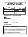
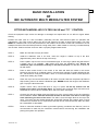
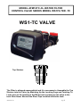
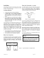
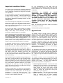
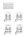
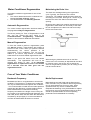
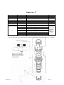
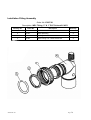
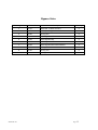
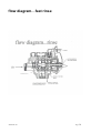
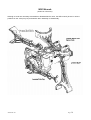
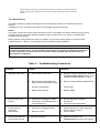
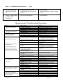
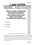
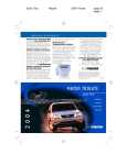
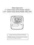
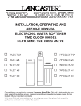
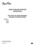
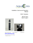
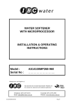
AUTOMATIC MULTI MEDIA FILTER
TIME CLOCK CONTROL
INSTALLATION & OPERATING
INSTRUCTIONS
Model :
Serial No :
AFM12TC-CL
………………………..
Manufacturer and Supplier of
FILTRATION & WATER TREATMENT PRODUCTS
for commercial, industrial and residential application
Telephone: (07) 3219 2233
Email: [email protected]
AFM12TC-CL
Facsimile: (07) 3219 2266
Website: www.ibcwater.com.au
Page 1
GENERAL WATER FILTER
PERFORMANCE DATA SHEET
Time Clock
Model No.
AFM12TC-CL
Service
Flow Rate
Backwash
Flow Rate
Flow
LPM
Flow
LPM
55
42
Pipe Size
Approx.
Shipping
Weight
(kg)
Space
Required
Inlet
Outlet
Drain
mm
mm
Per Kg
metres
25BSP”
”F”
20
105
0.7x 0.6x1.75
WxDxH
Media Operating Conditions :
Suspended Solids Max.100mg/l
Water pH:
5.5----9.0
System Operating Pressure:
250 - 690 kPa
Temperature:
4o x 43oC
Electrical:
240V—16VAC 50Hz 3 watts maximum
Control Valve:
Series WS1Filter -TC with bypass valve and
Installation fittings
.
Note : This Filter is only suitable to remove suspended particles only and will not remove
dissolved material in solution
WARNING
A pressure reduction valve must be installed in areas of high water pressure (above 690kPa)
A water hammer arrestor must be installed if water hammer prevails, between the softener
and the closing off device.
Caution: Do not use where water is microbiologically unsafe or with water of unknown
quality.
Check with the relevant Local Authority when required to see if any further safety measures
are necessary if connecting the filter onto a Town water mains Supply
AFM12TC-CL
Page 2
FAILURE TO OBSERVE WARNINGS WILL VOID WARRANTY
BASIC INSTALLATION
OF
IBC AUTOMATIC MULTI MEDIA FILTER SYSTEM
FITTED WITH MODEL WS1 FILTER VALVE and “TC “ CONTROL
Check the equipment upon arrival for damage or shortages and report same to our Office or Agent before
starting.
Position the Filter Tank on a firm foundation, preferably concrete, with sufficient space for operation and
maintenance. The Filter must be within One and a Half metres of a 240V-10 amp Power Outlet .The Filter
MUST be installed under cover and protected from the weather as the Valve control and Transformer are not
waterproof and the filter should be placed far enough away from a water heater to avoid any hot water backup
into the filter. Position the filter close to a drain or properly trapped waste outlet.
STEP 1
Make sure the tank is empty and clean.
STEP 2
Install the distributor tube in the tank, check the height in relation to top of the tank.
(Approximately 12mm above the top of the tank).
STEP 3
Place a plastic cap over the end of the distributor pipe. A clean rag or plastic bag will suffice if
a plastic cap is not available - NO media must enter the distributor pipe. Ensure the
distributor pipe is maintained centrally in the tank at all times. Fill the tank to about 1/3
full with water.
STEP 4
Place a wide mouth funnel in the mouth of the tank and load the media in the correct
sequence with the No. 6 underbed gravel in first and then load the D1 media followed by the
D2 , 7M sand and finally the D3 media . Note:- It is recommended to utilise a Dust Style face
mask when loading any media.
STEP 5
Clean the top of the tank and threads of all traces of media. Remove the plastic cap fitted in
Step 3 taking care not to raise the distributor pipe. NEVER shorten the length of the distributor
pipe. Top up the tank with water.
STEP 6
Unpack control valve, check that tank ‘O’ ring is in place. Fit the top strainer into the
bottom of the valve if not already fitted. The strainer has a bayonet style connection end.
Assemble the control valve to softener tank, and screw down hand tight.
STEP 7
Connect the Inlet and Outlet pipes and Drain line to the control valve as per the instruction
book installation details. Note the directional arrows on the Valve. The inlet is on the right
hand side facing the front of the valve. The drain is from the larger elbow on the top of the
valve. The valve Inlet and Outlet threads are 25mm BSP Female with a 20mm push on Hose
connection for the drain line. If required the hose tail can be removed and the drain can either
be a 20mmBSP or 25mmBSP.
STEP9
Refer to Instruction booklet for start up procedure (placing conditioner into Service") and it is
recommended to read fully the instruction manual before commencing the installation and
placing the system into operation.
AFM12TC-CL
Page 3
MEDIA PLACEMENT
MULTI MEDIA SEDIMENT FILTER
Sequence in Tank
AFM12
1st
8 kg. of #6 Gravel
2nd
17 kg. of D1 Media
3rd
14 kg. of D2 Media
4th
26 kg. of 7M Sand
5th
20 kg. of D3 Media
AFM12TC-CL
Page 4
OPERATION
The multi media filter is designed to remove particular matter. It will not remove colloidal matter, this matter is
very fine particles usually not visible to the naked eye but in their finest form impart colour to the water.
Colloids remain in suspension even when the water is virtually at rest.
The multi media filtration system comprises a vessel or tank with various layers of filtration media. Each layer
is designed to remove a specific size of particle and at the bottom is a very fine layer of media, which
produces the high quality water from this style of filter.
The top mounted control valve controls the cleaning of the media. This valve directs the flow of water through
the tank, in the service cycle the flow is directed down through the media into the bottom strainer of the riser
pipe and up through the centre of the riser pipe and through various valve ports to the service line. The
cleaning cycle consists of two phases.
Phase 1 being back washing of the media. In back washing the control valve directs the incoming water down
through riser pipe to the bottom of the tank and lifts the media bed and removes the entrapped dirt/matter back
through the control valve to waste.
Phase 2 The media then settles back and the media is then rinsed to waste in a down flow purge operation
and the system returns to the service cycle.
All the above is automatically controlled by the Model WS1 Control Valve fitted with the “TC” low voltage
electronic timer control.
The TC low voltage timer control is a 16 volt system. The valve comes complete with a mains 240/18V
transformer. The lead of the transformer plugs into the single pin socket connector mounted on the back of
the timer.
The programmed in function “ Days To Regen.” controls the frequency of cleaning the media. This is a
maximum 99 day period programmable function. The days between backwashing or Regeneration and actual
Time Of Regeneration has to programmed in at commissioning . The time period is determined based on the
degree of suspended matter in the raw water and is generally adjusted by monitoring the build up of the
pressure differential across the media bed.
The frequency of cleaning can only be determined under the specific site conditions. It is recommended that
inlet and outlet pressure gauges are installed and the pressure differential is noted when the filter is first put
into service, ie. the difference between the inlet and outlet pressure gauges when water is flowing through the
filter. As the dirt is being removed by the filter, the pressure differential will increase.
The inlet pressure reading will rise and the outlet pressure will drop. When the pressure difference increases
by 35Kpa (5psi) over than what it was when clean at the beginning. Then the filter needs to be back washed.
The factory program function “Time Of Regeneration” is designed to clean the filter in the early hours of the
morning 2.00-2.30 am. If a different time is desired then it is necessary to reprogram in the desired time.
Eg. if on first starting the filter the pressure differential was 60 kPa then when it increases to 105Kpa the filter
should be cleaned. However, as the control is a time based system then it has to be related to days of
operation. If in the example above it took 3 days to reach the increase for the 35Kpa pressure differential then
the filter should be cleaned every third day.
If pressure gauges are not available then it is suggested to initially set up the unit to clean every third day and
then adjust these settings if necessary based on loss of pressure and flow rate. However, the unit must be
cleaned at least once a week.
The filter can be manually initiated for cleaning by pressing the relevant keys on the front panel.
AFM12TC-CL
Page 5
CUSTOMER/ INSTALLER
PROGRAMING INSTRUCTIONS
The WS1-TC has been factory programmed with the majority of the commands and parameters installed. It is
necessary on commissioning of the filter to program in the “DAYS” between Media Backwashing and if desired
another time of day when Backwashing is to proceed or accept the factory default of 2am and to set up the
clock to register the current time of day. The supplied transformer plugs into the back socket mounted
on the back face of the front panel of the valve .
The procedure is as follows :
Plug in the transformer into the mains and turn on – Press “Set Hour” and
Down Buttons
simultaneously and hold for about 3—5 seconds and then valve will sequence to the service position.
Setting Time and Period Between Media
Backwash.
Step 1ID – To enter installer display press the SET
HOUR and ▲ buttons simultaneously for
approximately 5 seconds and release when “2”
flashes. This is the factory programmed Time Of
Regeneration at 2 am. If this default time needs to
be changed proceed as 2ID. If acceptable press
SET HOUR button and go to 3ID.
Step 2ID– Using the
keys input desired Time
Of Backwash . Note the clock is a 24 hour display
and only hours not minutes can be programmed
in. Press SET HOUR to go to Step 3ID
Step 3ID – Days between Backwash
Use or buttons to Set the days between
Backwash . Minimum of once a week. See page 13
Press SET HOUR to exit.
Setting Current Time of Day
Step 1U:
Push SET HOUR button .TIME -HOUR screen will
Flash.
Step 2U:
Set the display to the closest HOUR by using the
buttons. Note the display is a 24 hour clock.
Press SET HOUR button to exit.
After a power outage, the current Time Of Day will
have to be reset
Note : Display will Show “Days to Regen”
Regen is the same as Backwash.
AFM12TC-CL
Page 6
Power outage
When electric power is interrupted the microprocessor will hold all relevant information in memory except for
the current time of day.
Current time of day
When power is restored the display will Flash and go to the Time-Hour Setting. Press SET HOUR and input
the current Time OF Day. If power is lost during a Backwash cycle the valve will remain operational in
the current cycle and will recommence electrically in that cycle when power is restored.
In long power outages it is advisable to check that the system is not in a Backwash cycle that could be
discharging water to drain and in this instance it would be advisable to place the valve in bypass
mode until power is restored.
General
Note: When changing valve operational cycles the valve control will emit a number of whirring sounds.
Note :- The valve cannot be positioned into the regeneration mode without ELECTRIC Power.
USER DISPLAYS.
General Operation
When the system is operating one or two displays will be shown. Pressing
the UP or DOWN button will alternate between the displays. One of the
displays is the Current Time of Day to the nearest HOUR and the second
Display is the days remaining until the next Backwash. If the days
remaining is equal to ONE then Backwashing will take place at the next
preset time. The user can scroll between the displays as desired.
If the system has called for a backwash at the preset time then an arrow
will point to “Regen.“ on the panel face.
Regeneration / Backwash Mode
Typically a filter is set to backwash at a time of NO or low water usage.
Factory default is 2 am . If there is a demand for water when the system
is backwashing then Unfiltered water only will be available. If a system
demands that no Unfiltered is bypassed during regeneration , then the
Filter will have to have a Bypass Prevention Solenoid Valve fitted.
When the system begins to Backwash , the display will change to indicate
the various cycles of the regeneration process C1>C4 and an arrow will
point to Regen. The system will automatically step through the
regeneration cycles and reset back to the service cycle when the
Backwash is complete.
Manual Backwash / Regeneration
A manual Backwash can be initiated in two ways.
Delayed or Immediate.
For Delayed at the preset time of regeneration: Simultaneously Press
▲▼buttons together and release. An arrow will appear next to Regen.
Backwash will take place at the preset time (This request can be
cancelled if necessary by again simultaneously pressing the ▲▼buttons
together.)
For Immediate regeneration: Simultaneously Press ▲▼buttons
together for about 5 seconds until the valve changes to the C1 mode.
The Filter will begin to Backwash immediately . This request cannot be
cancelled.
AFM12TC-CL
Page 7
MODEL AFM12TC-CL WATER FILTER
CONTROL VALVE SERIES MODEL WS1FILTER -TC
WS1-TC VALVE
Top Strainer
The Filter is shipped unassembled and it is necessary to Assemble the Top
Strainer into the Valve( by Matching Up the Locating Lugs and Twisting To
Lock) prior to the loading of the Media and screwing on the valve to the
tank. Note Never Shorten the Riser Pipe installed inside the tank.
AFM12TC-CL
Page 8
GENERAL” WS1 TC” CONTROL VALVE
FILTER SPECIFICATONS
Inlet/Outlet Fittings
25mm BSPF PVC elbows
Cycles
Valve Material
Regeneration
3
Noryl (1) or equivalent
Down flow
FLOW RATES:- Maximum ---Valve Only
Service @15psi/1 bar drop (includes bypass & meter)
102 lpm
Backwash @25psi/1.7 bar drop (includes bypass)
Note : Actual Flow rates will depend on the filter media
OPERATING PRESSURE
102 lpm
Minimum/Maximum
250-600 kpa (35-100 psi)
OPERATING TEMPERATURE
5°C---43°C
DIMENSIONS & WEIGHT
Distributor Pilot
Drain Line
1.050” OD Pipe (3/4” NPS)
1” (25mm) BSP-F or 20mm Hose Tail
Mounting Base
Height from Top of Tank
2 /12” – 8 NPSM
7 3/8” (187mm)
Weight
Distributor Pilot
ELECTRICAL SPECIFICATIONS
4.5lbs (2kg)
12mm Above Tank Top
AC Adaptor
Supply Voltage
Supply Frequency
Output Voltage
230V AC
50 Hz
12—16 V AC
Output Current
500 mA
CYCLES OF OPERATION
Factory Set
Minutes
C1
C4
C0
14
8
st
Backwash 1 (upflow)
Fast Rinse (downflow)
Service (down flow)
Note C1 to C4 are fixed values and cannot be varied.
(Noryl is a trademark of General Electric)
AFM12TC-CL
Page 9
Table of Contents
Specifications ……………………………………………………………9
Introduction ………………………………………………………………11
Special Features
General Conditioner Information …………………………………….. 11
How Your Conditioner Works
Model TC Control Front Panel
Installation – important installation details….…………………….. 12-13
Bypass Valve …………………………………………………………… 13-14
Water Conditioner Regeneration ………………………………….…. 15
Automatic Regeneration
Manual Regeneration
Care of Your Water Conditioner ……………………………………… 15
General Backwash Frequency
Maintaining the Drain Line
Media Replacement
Placing Filter into Operation …...………………………………….…. 16
Valve Manual …………………………………………………………….. 17-18
Replacement Parts …………………………………………………….... 19-28
Service Instructions………………………………………………………28-32
Troubleshooting ………………………………………………….……… 33-34
Alarms
Troubleshooting Procedures
Glossary of Terms …………………………………………………….…. 35
Safety
Caution
Warning
The plug-in transformer for this
equipment is rated for indoor use
only.
Never attempt o work on this control while
standing in or near water without
disconnecting electrical power to the
control.
AFM12TC-CL
Page 10
Introduction
The Model TC Control provides sophisticated
Electronic Time Clock-based water conditioning. The
control is factory default programmed for the majority
of the required settings and only requires simple
minimal on site programming for the remaining
settings to suit the specific installation.
The control provides efficient, trouble free, filtered
water.
The Series WS1-TC valve combines design simplicity
with glass reinforced NORYL* plastic construction to
provide an uncommonly reliable appliance.
If maintenance becomes necessary, the Model WS1TC water Conditioner System has the capability for
quick repairs.
NORYL is a trademark of GE Plastics.
Special Features
•
•
•
•
Memory Retention. During a power outage,
critical operating information in the control's
memory is stored in a special electronic device
called a NOVARAM. When power is restored, the
information is returned to the microprocessor and
operation resumes as if an outage never
occurred. The time of day will be late by the
length of the power outage. Because most power
outages are less than one minute in duration, it
may be months or years before the time display
requires resetting. If an outage of one or more
hours occurs, the time of day should be reset but
no other reprogramming is necessary.
Design Reliability. Solid-state electronics assure
many years of trouble-free performance.
Days between Regeneration and Time Of
Regeneration. Once the settings are entered, the
information cannot be lost due to a power outage,
so reprogramming is not necessary.
Manual Regeneration . An extra regeneration
can be achieved at any time by pressing the
▲▼buttons on the front panel. It takes a few
minutes for the regeneration to start. The unit
completes the regeneration in about thirty
minutes. This feature is beneficial when you
expect to use more than the normal amount of
water. The manual regeneration can be set for
immediate regeneration or delayed regeneration
at the programmed in time of regeneration
normally at 2am.
General Conditioner Information
How the Water Filter Works
In general, your water filter works in the following
manner. Unfiltered water flows into the filter and
through the media bed where the specific
contaminant in the water is removed or Adsorbed.
The conditioned water flows out of the media bed into
your plumbing system. After a certain amount of
water has passed through the filter, the media cannot
remove any more contaminant or the flow rate drops
due to suspended matter build up in the media and
indicates that the media needs to be backwashed or
regenerated. This process restores the filter's ability
to treat the water. The regeneration process cleans
the filter bed by backwashing and rinsing the media to
remove suspended matter and to recondition the
media to adsorb specific contaminants. Various
Media are available to perform a specific function.
The filter is set to regenerate based on a programmed
in “Days Between Regeneration “
Figure 1
Model TC Control Front Panel
The main components of the model TC Control front
panel are:
• Main Display Screen
• Display screen – set as time of day or days to
regeneration
• Programming Push Buttons
•
•
Note : The term “REGENERATION” for a Filter
Application is the same as the more common
term “BACKWASH’
AFM12TC-CL
•
Three-cycle operation provides for down flow
conditioned water, upflow backwash, down flow
fast rinse.
System operation cannot get out of phase or
sequence. The control always returns to a fixed
conditioned water position after regeneration.
Bypass unfiltered water is automatically available
during regeneration unless a prevention solenoid
valve is fitted.
Page 11
Installation
Drain Line Connection – to sewer
All plumbing and electrical connections must conform
to local codes. Inspect the unit carefully for carrier
shortage or shipping damage.
The ideal location for the unit is above and not more
than 6.1m (20ft) from the drain. For such installations,
using the appropriate adaptor fitting (supplied),
connect 20mm (3/4”) plastic tubing to the drain line
connection located on the top of the valve.
Location Selection
•
•
•
Locate unit as close to a drain as possible
If supplementary water treating equipment is
required, make sure that adequate additional
space is available. Locate the cabinet softener in
an accessible place so that salt can easily be
added.
Do not install any unit closer than 3m (10ft) of
piping between the outlet of the water conditioner
and the inlet of the water heater. Water heaters
can transmit heat back down the cold water pipe
into the control valve. Hot water can severely
damage the controller.
A 3m total pipe run (including bends, elbows etc) is a
reasonable distance to prevent hot water damage. A
positive way to prevent hot water from flowing from a
heat source to the conditioner is to install a check
valve in the soft water piping from the conditioner. If a
check valve is installed, make sure that the waterheating unit is equipped with a properly rated
temperature and pressure safety relief valve. Always
conform to local codes.
•
•
•
Do not locate the unit in an area where the temp
ever falls below 1ºC (34ºF) or over 49ºC (120ºF).
Do not install the unit near acid or acid fumes.
Do not expose the unit to petroleum products.
Water Line Connection
If the unit is located more than 6.1m (20ft) from the
drain, use 25mm tubing for runs up to 12.0m. You
may elevate the line up to 1.8m providing the run
does not exceed 4.5m and the water pressure at the
conditioner is not less than 380kPa (55psi.) You may
elevate an additional 500mm for each additional
70kPa. (10psi) of water pressure.
When the drain line is elevated and empties into a
drain which is below the level of the control valve,
form a 170mm (7 inch ) loop at the drain end of the
line so that the bottom of the loop is level with the
drain line connection. This provides an adequate
siphon trap.
If the drain empties into an overhead sewer line, a
sink-type trap must be used.
Caution
A bypass valve system must be installed to provide
for occasions when the water conditioner must is bypassed for hard water or for servicing. Bypass offers
simplicity and ease of operation. These filters are
equipped as standard with a bypass valve. See pages
13 and14
Not In Bypass
Figure 5 - Air Gap Installation
Never connect the drain line into a drain,
sewer line or trap. Always allow an air gap
between the drain line and the wastewater
to prevent the possibility of sewage being
back-siphoned into the conditioner.
In Bypass
Figure 3 – Typical Illustration of a Bypass Valve
AFM12TC-CL
Page 12
Important Installation Details
The control valve, fittings and/or bypass are designed
to accommodate minor plumbing misalignments but
are not designed to support the weight of the system
or the plumbing.
Do no use Vaseline, oils, other hydrocarbon lubricants
or spray silicone anywhere. A silicone lubricant may
be used on black o-rings but is not necessary. Avoid
any type of lubricants, including silicone, on the
clear lip seals.
The nuts and caps are designed to be unscrewed or
tightened by hand or with the special plastic wrench.
Do not use a pipe wrench to tighten or loosen nuts or
caps. Do not place a screwdriver in the slots on caps
and/or tap with a hammer.
Do not use pipe dope or other sealant on threads.
Use teflon tape on threaded inlet, outlet and drain
fittings. Teflon tape is not necessary on the nut
connection or caps because of o-ring seals.
After completing any valve maintenance involving
the drive assembly of the drive camp assembly
and pistons, unplug power source jack from the
circuit board (black wire) and plug back in. This
resets the electronics and establishes the service
piston position. The display should flash and then
reset the valve to the service position if necessary.
All plumbing should be done in accordance with local
plumbing codes. The pipe size for the drain line
should be a minimum of 20mm inside diameter.
Solder joints near the drain must be done prior to
connecting the drain line flow control fitting. Leave at
least 150mm (6”) between the drain line control fitting
and solder joints when soldering pipes that are
connected on the drain line control fitting. Failure to
do this could cause interior damage to the drain line
flow control fitting.
When assembling the installation fitting package (inlet
and outlet), connect the fitting to the plumbing system
first and then attach the nut, split ring and o-ring.
Heat from soldering or solvent cements may damage
the nut, split ring and o-ring. Solder joints should be
cool and solvent cements should be set before
installing the nut, split ring or o-ring. Avoid getting
primer and solvent cement on any part of the o-rings,
bypass valve or control valve.
Position the filter within 1½ metres of a 10 amp GPO.
The transformer is connected into the plug socket on
the back of the valve control panel. Do not drop the
transformer or have the cable too taut.
The
transformer is only suitable for internal use only.
The filter must be weather protected.
AFM12TC-CL
For full understanding of the water filter we
recommend that the instruction manual be fully read
before installation and commissioning of the filter be
undertaken.
IMPORTANT:
A
NUMBER
OF
VALVE
COMPONENTS ARE LOCKED INTO POSITION
WITH
EASILY
REMOVABLE
CLIPS.
ENSURE ALL LOCKING CLIPS ARE CORRECTLY
IN POSITION BEFORE PRESSURISING THE
SOFTENER. ENSURE THAT IT IS POINTED OUT
TO ALL RELEVANT PERSONNEL THAT THE
LOCKING CLIPS MUST NOT BE REMOVED
WHILST THE SYSTEM IS UNDER WATER
PRESSURE.
Note: All electrical connections must be connected
according to local codes.
Install grounding strap on metal plates.
Bypass Valve
The bypass valve is typically used to isolate the
control valve from the plumbing system’s water
pressure in order to perform control valve repairs or
maintenance. The WS1 bypass valve is particularly
unique in the water treatment industry due to its
versatility and state of the art design features. The
full flow bypass valve incorporates four positions,
including a diagnostic position that allows service
personnel to work on a pressurised system while still
providing untreated bypass water to the facility or
residence. Its completely non-metallic, all plastic
design allows for easy access and serviceability
without the need for tools.
The bypass body and rotors are glass filled Noryl (or
equivalent) and the nuts and caps are glass filled
polypropylene. All seals are self-lubricating EPDM to
help prevent valve seizing after long periods of nonuse. Internal o-rings can easily be replaced if service
is required.
The bypass consists of two interchangeable plug
valves that are operated independently by red arrowshaped handles.
The handles identify the flow
direction of the water. The plug valves enable the
bypass valve to operate in four positions.
1. Normal Operation Position: The inlet and outlet
handles point in the direction of flow indicated by
the engraved arrows on the control valve. Water
flows through the control valve during normal
operation and this position also allows the control
valve to isolate the media bed during the
regeneration cycle. (Figure 1)
2. Bypass Position: The inlet and outlet handles
point to the centre of the bypass, the control
valve is isolated from the water pressure
contained in the plumbing system. Untreated
Page 13
water is supplied to the plumbing system. (Figure
2)
3. Diagnostic Position: The inlet handle points in
the direction of flow and the outlet handle points
to the centre of bypass valve, system water
pressure is allowed to the control valve and the
plumbing system while not allowing water to exit
from the control valve to the plumbing.(Figure 3)
4. Shut Off Position: The inlet handle points to the
centre of the bypass valve and the outlet handle
points in the direction of flow, the water is shut off
to the plumbing system (i.e. plumbing connection
somewhere in the building bypasses the system).
(Figure 4)
AFM12TC-CL
Page 14
Water Conditioner Regeneration
Maintaining the Drain Line
Your water conditioner regenerates for one of two
reasons:
• The control determines that the conditioner has
reached the Days to Regen. setting.
• The REGEN button was manually pressed.
The drain line discharges during the regeneration
cycle. Typically, the line drains into a sewer
connection. The installer should plumb the drain line
according to local codes, leaving a 25—50mm air gap
between the end of the drain line and the drain
opening.
Automatic Regeneration
The control makes regeneration decisions based on
the programmed Days to Regeneration.
Be sure that the drain line remains unrestricted so the
regeneration waste water can flow freely to the drain.
Do not set objects on the drain line that could crimp
the line and restrict flow.
The factory setting for Time of Regeneration is 2:00
AM. You can change this time. Refer to the
Customer/Installer Programming Instructions
section in this manual for additional information.
Manual Regeneration
To force the control to perform a regeneration, press
the ▲▼push buttons. These buttons are located on
the front of the control. When you press the buttons
simultaneously the control performs a full
regeneration of the conditioner. You can use this
feature if you need a large amount of conditioned
water before the next scheduled regeneration date.
Note: If you press this button once and release
immediately. The regeneration will occur at the
delayed time setting i.e. 2am. If an immediate
regeneration is required then hold in the button
for 3 seconds until the filter goes into the
regeneration mode.
General
When doing any Maintenance work on the filter
control valve it is necessary to depressurise the valve
by opening a tap in the service line or putting the
valve in a regeneration position prior to closing off the
inlet and outlet valves .
Care of Your Water Conditioner
Backwash Frequency
Media Replacement
Backwash the filter on a regular basis to suit the site
conditions. The frequency of cleaning the media bed
can only be determined under specific site conditions
. It is recommended to install inlet and outlet pressure
gauges and the difference in gauge readings with a
clean media bed be recorded and a cleaning
frequency be based on the length of time in days for
an increase of the pressure differential (between inlet
and outlet )and to clean the filter when the differential
increases by 35 Kpa (5psi). It is recommended that
the Filter be backwashed at least once a week.
Multi Media gravel and Sand and the Garnets and
Filter Coal have very low attrition rates and generally
do not need replacement for many years. When
operated under very severe conditions without
adequate backwashing it may be desirable to replace
the media on a more regular basis however the filter
should be operated within the normal operating
parameters and backwashed as necessary.
.
AFM12TC-CL
Page 15
11. Press the “▲▼” buttons in once simultaneously
Placing Filter into Operation
and release and again press but hold for 3
seconds until regeneration starts.
Initial Start-Up
1. Raw water turned off to unit or bypass valve in
shut off mode.
12. Allow the system to complete a full regeneration
and return to the service position. This will take
approximately thirty minutes.
2. Connect transformer to power point and turn on.
3. Program controller as per “Customer/Install
Programming Instructions”. Page 6
13. When the unit has returned to the service position
with the normal display then open the bypass
valve outlet valve slowly to enable water to enter
the treated water line ensure that the bypass
valve is correctly in “Normal Operation” position.
4. Press the “▲▼” buttons in once simultaneously
and release and again press but hold for 3
seconds until regeneration starts.
Open a tap in the treated water and allow to run
to drain for a few minutes. Then check the quality
of the treated water.
5. The filter will advance to the backwash position
”C1”.
6. Slowly open the inlet valve or the bypass valve
into the “Diagnostic Mode” approximately one
quarter of a turn and allow the mineral tank to
slowly fill up with water.
Caution
If the water supply valve is opened too rapidly
or too far, Media may be lost. In the
BACKWASH position, you should hear air
escaping slowly from the drain line.
7. When all the air is purged from the tank (water
begins to flow steadily from the drain), slowly
open the main supply valve all the way. Allow the
water to run into the drain until the water appears
clear. Turn off the water supply and wait for a few
minutes to allow all trapped air to escape from the
tank. Then open the inlet valve/bypass inlet
slowly and allow to backwash for a short period.
8. Press the “▼OR▲” button and allow valve to
position into the rinse cycle “C4”. Once the valve
is positioned then again press “▼OR▲” and allow
to advance to “C0” position .
9. The valve will then go back into the service
mode.
10. It is necessary to give a new filter a complete
regeneration before placing fully into service.
AFM12TC-CL
Page 16
WS1-TC Manual
Control Valve Function and Cycles
of Operation
This glass filled Noryl1 (or equivalent) fully automatic
Time Clock control valve is designed as the primary
control center to direct and regulate all cycles of a
water Filter. The control valve is set to regenerate as
a time clock (passage of a particular number of days).
The control valve is factory set to regenerate with a
delay regeneration set for 2am.
The control valve is capable of routing the flow of
water in the necessary paths to regenerate the media.
The control valve regulates the flow rates for
backwashing and rinsing.
The control valve uses no traditional fasteners (e.g.
screws); instead clips, threaded caps, nuts and snap
type latches are used. Caps and nuts only need to be
firmly hand tightened because radial seals are used.
Tools required to service the valve include one small
blade screw driver, one large blade screw driver,
pliers and a pair of hands. A plastic wrench is
available which eliminates the need for screwdrivers
and pliers. Disassembly for servicing takes much less
time than comparable products currently on the
market. Control valve installation is made easy
because the distributor tube can be cut 12.7mm (1/2“)
above to 12.7 mm (1/2“) below the top of tank thread.
The distributor tube is held in place by an o-ring seal
and the control valve also has a bayonet lock feature
for upper distributor baskets.
The AC adapter power pack comes with a 2.0 meter
power cord and is designed for use with the control
valve. The AC adapter power pack is for dry location
use only.
•
•
•
•
•
•
Solid state microprocessor with easy access
front panel settings.
Front panel display for time of day, days to
regeneration and Regeneration sequence
steps.
Fixed 3-cycle control delivers controlled
backwash, fast rinse and down flow service.
12-volt output AC Adapter provides safe and
easy installation.
Control valve design provides optimum
service and backwash rates.
Reliable and proven DC Drive.
Manual Initiated Regeneration
AFM12TC-CL
The user can initiate manual regeneration. The user
has the option to request the manual regeneration at
the delayed regeneration set time or to have the
regeneration occur immediately:
1. Delayed Regeneration : Pressing and
releasing immediately the ▲▼buttons. “ƒ”
will flash towards regen on the display and
regeneration will occur at the delayed
regeneration time. The user can cancel this
request by pressing and releasing the
▲▼buttons.
2. Or for immediate regeneration : As for
delayed but Again Pressing and holding the
▲▼buttons for approximately 3 seconds will
immediately start the regeneration. The user
cannot cancel this request.
3. The user can manually step through the
regeneration process to check to see that the
valve is functioning correctly by using the
▲OR ▼buttons to go to the next step in the
regeneration process ie.: C1—C0.
Note: manually stepping through a
regeneration quickly will not actually
regenerate the filter but will only check to
see that the relevant steps are being
performed correctly.
The WS1EI control valve consist of the
following components:
1. Drive Assembly
2. Drive Cap Assembly, Main Piston.
3. Spacer Stack Assembly.
4. Drain Line Flow Control and Fitting Assembly.
5. Bypass Valve.
6. Installation Fitting Assemblies.
Drive Assembly
The drive assembly consists of the following parts:
• Drive Bracket.
• Printed Circuit (PC) Board.
• Motor
• Drive Gears
• Drive Gear Cover
The drive bracket holds the PC board, the motor, the
drive gears and the drive gear cover in place.
The PC board receives and retains information,
displays the information, determines when to
regenerate and initiates regeneration. The display
show different types of information in the initial
system set up, installer display settings, diagnostics or
user display settings.
The PC board powers the motor. The PC board’s twoprong jack connects wires to the direct current (DC)
motor. The motor is held in place on the drive bracket
by a spring-loaded clip and a small bulge in the
plastic, which fits in one of the slots on the motor
housing. The motor turns drive gears that drive the
piston to cycle positions for backwashing,
Page 17
regeneration, rinsing, refill or service. The motor is
fully reversible (turns both ways) and changes
direction of rotation to change the direction of piston
motion. The motor is easily replaced if necessary.
There are three drive gears held in place by the drive
gear cover. All three drive gears are the same size. A
reflective coating is applied to the gears. As the
centre drive gear turns a light shines on the coating
and a light sensing diode determines if a light pulse
was returned. The PC board counts the pulses and
determines when to stop driving the motor.
The drain line flow control and fitting are located on
top of the control valve and replaceable without the
use of special tools.
The drain line flow control is installed in the standard
1” Straight drain line, which accommodates 25mm
and 20mm BSP threaded drain line connections. The
drain line elbow can be rotated 180 degrees so the
outlet can be orientated to the nearest drain. This
filter unit is supplied with a 20mm push on Hose
Fitting which can be removed if desired to utilise the
20 or 25 mm BSP Female Porting.
Drive Cap Assembly, Main Piston
The drive gears turn the main gear of the drive cap
assembly, which moves the piston. The screw-driven,
horizontally moving piston stops at specific positions
to direct the flow of water to backwash, rinse. The PC
board determines the position of the piston by
counting pulses produced when the piston is moved.
An optical sensor looking at one of the reduction drive
gears generates these pulses. Each cycle position is
defined by a number of pulses. The counter is zeroed
each time the valve goes to the service position. The
PC board finds the service position by noting the
increase in current delivered to the motor when the
mechanical stop at the service position is reached.
This method of controlling the piston position allows
for greater flexibility and requires no switches or cams
(U.S. Patent 6,444,127).
Installation Fitting Assemblies
The installation fittings are used to connect the
bypass to the plumbing system. Standard fittings
supplied are 25mm BSP Female Thread PVC.
Both elbow fittings have a unique drill out feature to
allow a ¼” NPT connection to the inlet and/or outlet
which can be used for a RO feed, test ports, pressure
tap ports, etc.
Spacer Stack Assembly
The spacer stack assembly provides the necessary
flow passage for water during the different cycles.
The all-plastic spacer stack assembly (U.S. Patent
6402944) is a one-piece design which allows the
stack to be removed using your fingers.
The exterior of the stack is sealed against the body
bore with self lubricating EPDM o-rings, while the
interior surface is sealed against the piston using
slippery self cleaning silicone lip seals. The lip seals
are clear in colour and have a special slippery coating
so that the piston does not need to be lubricated.
Drain Line Flow Control and Fitting
Assembly
The drain line flow control assembly includes a drain
line flow control and a fitting. The drain line flow
control allows proper media bed expansion by
regulating the flow rate to the drain. The drain line
flow control is a flexible washer-like part with an
orifice and a precision moulded contour. The flow
rates are within ± 10% over the pressure range of 1.4
bar (20 psi) to 6.9 bar (100psi).
AFM12TC-CL
Page 18
SPARE PARTS
AND
SERVICING INSTRUCTIONS
AFM12TC-CL
Page 19
WS1-TC Front Cover and Drive Assembly
Drawing No.
Order No.
Description
Quantity
1
V3175TC-01
WS1TC Front Cover Assembly
1
2
V3107-01
WS1 Motor
1
3
V3106-01
WS1 Drive Bracket & Spring Clip
1
4
V3108TC
WS1 PC Board
1
5
V3110
WS1 Drive Gear 12x36
3
6
V3109
WS1 Drive Gear Cover
1
V3002TC
WS1TC Drive ASY
*
V3186-01
WS1 AC ADAPTER CORD ONLY
1
Not Shown
* Drawing number parts 2 through 6 may be purchased as a complete assembly, part V3002TC
AFM12TC-CL
Page 20
WS1TC Drive Cap Assembly, Downflow Piston, and Spacer Stack
Assembly
Drawing No.
Order No.
Description
Quantity
1
V3005
WS1Spacer Stack Assembly
1
2
V3004
Drive Cap ASY
1
3
V3178
WS1 Drive Back Plate
1
4
V3011
WS1 Piston Downflow ASY
1
6
V3135
O-ring 228
1
7
V3180
O-ring 337
1
8
V3105
O-ring 215 (Distributor Tube)
1
Not Shown
V3001
WS1 Body ASY Downflow
1
AFM12TC-CL
Page 21
Refill Port Plug
Drawing No.
AFM12TC-CL
Order No.
Description
Quantity
1
V3195-01
WS1 Refill Port Plug Assy
1
2
H4615
Elbow Locking Clip
1
6
V3163
O-ring 019
1
Page 22
Drain Line – 1”
Drawing No.
1
2
3*
4*
5*
6*
7*
8*
Order No.
Description
Quantity
H4615
Elbow Locking Clip
1
V3008-02
WS1 Drain FTG 1 Straight
1
V3166
WS1 Drain FTG Body 1
1
V3167
WS1 Drain FTG Adapter 1
1
V3163
O-ring 019
1
V3150
WS1 Split Ring
1
V3151
WS1 Nut 1” QC
1
V3105
O-ring 215
1
V3190-90
WS1 DLFC 9.0 gpm for 1
34 lpm
V3190-100
WS1 DLFC 10.0 gpm for 1 38lpm
One DLFC
V3190-110
WS1 DLFC 11.0 gpm for 1 42 lpm
must be
V3190-130
WS1 DLFC 13.0 gpm for 1 49 lpm
9
used if 1”
V3190-150
WS1 DLFC 15.0 gpm for 1 57 lpm
fitting is
V3190-170
WS1 DLFC 17.0 gpm for 1 64.5 lpm
used
V3190-200
WS1 DLFC 20.0 gpm for 1 76 lpm
V3190-250
WS1 DLFC 25.0 gpm for 1 95 lpm
Filters are supplied with a 20mm Push ON Hose Connection as standard fitted into a 25 BSP Elbow.
* Can be ordered as a set. Order Number V3008-02, description :WS1 Drain Fitting FTG 1 Straight
`
AFM12TC-CL
Page 23
Installation Fitting Assembly
Order No: V3007-01
Description: WS1 Fitting ¾” & 1” PVC Solvent 90۫ ASY
Drawing No.
AFM12TC-CL
Order No.
Description
Quantity
1
V3151
WS1 Nut 1” Quick Connect
2
2
V3150
WS1 Split Ring
2
3
V3105
O-Ring 215
2
4
V3189
WS1 Fitting ¾ & 1 PVC Solvent 90
2
Page 24
Bypass Valve
Drawing No.
AFM12TC-CL
Order No.
Description
Quantity
1
V3151
WS1 Nut 1” Quick Connect
2
2
V3150
WS1 Split Ring
2
3
V3105
O-ring 215
2
4
V3145
WS1 Bypass 1” Rotor
2
5
V3146
WS1 Bypass Cap
2
6
V3147
WS1 Bypass Handle
2
7
V3148
WS1 Bypass Rotor Seal Retainer
2
8
V3152
O-ring 135
2
9
V3155
O-ring 112
2
10
V3156
O-ring 214
2
Page 25
Flow Diagrams – Service and Backwash
AFM12TC-CL
Page 26
AFM12TC-CL
Page 27
flow diagram…fast rinse
AFM12TC-CL
Page 28
WS1 Wrench
(Order No. V3193-01)
Although no tools are necessary to assemble or disassemble the valve, the WS1 wrench (shown in various
positions on the valve) may be purchased to aid in assembly or disassembly.
AFM12TC-CL
Page 29
Service Instructions
Drive Assembly
Remove the valve cover to access the drive assembly.
Disconnect the power source plug (black wire) from the PC board prior to disconnecting the motor from the PC
board. The power source plug connects to the four-pin jack. The motor plug connects to the two-pin jack on the
left-hand side of the PC board.
The PC board can be removed separately from the drive bracket but it is not recommended. Do not attempt to
remove the display panel from the PC board. Handle the board by the edges. To remove the PC board from
the drive bracket, unplug the power, and motor plugs from the PC board. Lift the middle latch along the top of
the drive bracket while pulling outward on the top of the PC board. The drive bracket has two plastic pins that
fit into the holes on the lower edge of the PC board. Once the PC board is tilted about 45° from the drive
bracket it can be lifted off of these pins. To reinstall the PC board, position the lower edge of the PC board so
that the holes in the PC board line up with the plastic pins. Push the top of the PC board towards the valve
until it snaps under the middle latch, weave the power wires into the holders and reconnect the motor, and
power plugs. Note the power lead to the socket on the back face is very fragile at the soldered joints.
The drive bracket must be removed to access the drive cap assembly and pistons or the drive gear cover. It is
not necessary to remove the PC board from the drive bracket to remove the drive bracket. To remove the
drive bracket start by removing the four pin plug for the power source. Un weave the wires from the side
holders. Two tabs on the top of the drive back plate hold the drive bracket in place. Simultaneously lift the two
tabs and gently ease the top of the drive bracket forward. The lower edge of the drive bracket has two notches
that rest on the drive back plate. Lift up and outward on the drive bracket to disengage the notches.
To reassemble, seat the bottom of the drive bracket so the notches are engaged at the bottom of the drive
back plate. Push the top of the drive bracket toward the two latches. The drive bracket may have to be lifted
slightly to let the threaded piston rod pass through the hole in the drive bracket. Maintain a slight engaging
force on top of the drive bracket while deflecting the bracket slightly to the left by pressing on the side of the
upper right corner. This helps the drive gears mesh with the drive cap assembly. The drive bracket is properly
seated when it snaps under the latches on the drive back plate. If resistance is felt before latching, then
notches are not fully engaged, the piston rod is not in hold, the wires are jammed between the drive bracket
and drive back plate, or the gear is not engaging the drive cap assembly.
To inspect the drive gears, the drive gear cover needs to be removed. Before trying to remove the gear cover,
the drive bracket must be removed from the drive back plate. (Refer to the instructions above regarding
removing the drive bracket from the drive back plate. The drive gear cover can be removed from the drive
bracket without removing the motor or the PC board.) The drive gear cover is held in place on the drive
bracket by three clips. The largest of the three clips is always orientated to the bottom of the drive bracket.
With the PC board facing up, push in and down on the large clip on the drive gear cover. Handle the cover and
the gears carefully so that the gears do not fall off of the pegs in the cover.
Replace broken or damaged drive gears. Do not lubricate any of the gears. Avoid getting any foreign matter
on the reflective coating because dirt or oils may interfere with pulse counting.
The drive gear cover only fits on one way, with the large clip orientated towards the bottom. If all three clips
are outside of the gear shroud on the drive bracket the drive gear cover slips easily into place.
The drive bracket does not need to be removed from the drive plate if the motor needs to be removed. To
remove the motor, disconnect the power and motor plugs from the jacks on the PC board. Move the spring clip
loop to the right and hold. Rotate the motor at least a ¼ turn in either direction so the wires are vertical (up &
down) before gently pulling on the wire connectors to remove the motor. Pulling directly on the wires without
rotating the motor may break the wires off the motor.
AFM12TC-CL
Page 30
Replace the motor if necessary. Do not lubricate the motor or the gears. To reinstall the motor, move the
spring clip loop to the right and hold. Gently turn the motor while inserting so that the gear on the motor
meshes with the gears under the drive gear cover. Release the spring clip loop and continue to rotate the
motor until the wires are horizontal and the motor housing engages the small plastic bulge inside the drive
bracket motor retainer. Reconnect the motor plug to the two-pronged jack on the lower left hand side of the PC
board. If the motor will not easily engage with the drive gears when reinstalling, lift and slightly rotate the motor
before reinserting. Reconnect the power plug.
Replace the valve cover. After completing any valve maintenance, press SET HOUR and DOWN ▼buttons
for 3 seconds or unplug power source jack (black wire) at the circuit board and plug back in. This resets the
electronics and establishes the service piston position.
Drive Cap Assembly, Main Piston
The drive assembly must be removed to access the drive cap assembly. The drive cap assembly must be
removed to access the piston. The drive cap assembly is threaded into the control valve body and seals with
an o-ring. To remove the drive cap assembly use the special plastic wrench or insert a ¼” to ½” flat blade
screwdriver into one of the slots around the top 2” of the drive cap assembly so it engages the notches
moulded into the drive back plate around the top 2” of the piston cavity. The notches are visible through the
holes. Lever the screwdriver so the drive cap assembly turns counter clockwise. Once loosened, unscrew the
drive cap assembly by hand and pull straight out.
The drive cap assembly contains the drive cap, the main drive gear, drive cap spline, piston rod and various other parts that should not be
dissembled in the field. The only replaceable part on the drive cap assembly is the o-ring. Attached to the drive cap assembly is the main piston
(downflow).
To remove the main downflow or upflow piston fully extend the piston rod and then unsnap the main piston
from its latch by pressing on the side with the number. Chemically clean in vinegar, or replace the main piston.
Reattach the main piston to the drive cap assembly. Do not lubricate the piston rod, main piston. Lubricant will
adversely affect the clear lip seals. Reinsert the drive cap assembly and piston into the spacer stack assembly
and hand tighten the drive cap assembly. Continue to tighten the drive cap assembly using the special wrench
or a screwdriver as a ratchet until the black o-ring on the spacer stack assembly is no longer visible through
the drain port. Excessive force can break the notches moulded into the drive back plate.
AFM12TC-CL
Page 31
Make certain that the main drive gear still turns freely. The exact position of the piston is not important as long
as the main drive gear turns freely.
Reattach the drive assembly to the control valve and connect all plugs. After completing any valve
maintenance, press SET HOUR and DOWN ▼buttons for 3 seconds or unplug power source jack (black wire)
at the circuit board and plug back in. This resets the electronics and establishes the service piston position.
Spacer Stack Assembly
To access the spacer stack assembly remove the drive assembly, drive cap assembly and piston. The spacer
stack assembly can be removed easily without tools by using thumb and forefinger. Inspect the black o-rings
and clear lip seals for wear or damage. Replace the entire stack if necessary. Do not disassemble the stack.
The spacer stack assembly may be chemically cleaned with vinegar or wiped with a soft cloth.
The spacer stack assembly can be pushed in to the control valve body bore by hand. Since the spacer stack
assembly can be compressed it is easier to use a blunt object (15.9mm (5/8”) to 28.6 mm (1-1/8”) in diameter)
to push the centre of the assembly into the control valve body. The assembly is properly seated when at least
four threads are exposed (approximately 15.89 mm (5/8”). Do not force the spacer stack assembly in. The
control valve body bore interior can be lubricated with silicone to allow for easy insertion of the entire stack. Do
not use silicone or any other type of lubricant on the clear lip seals or the piston.
Reattach the drive cap assembly and piston and the drive assembly.
IMPORTANT NOTE:After completing any valve maintenance, press” SET HOUR and DOWN ▼buttons “for 3 seconds or
unplug power source jack (black wire) at the circuit board and plug back in. This resets the electronics
and establishes the service piston position.
Bypass Valve
The working parts of the bypass valve are the rotor assemblies that are contained under the bypass valve
caps. Before working on the rotors, make sure the system is depressurized. Turn the red arrow shaped handles
towards the centre of the bypass valve and back several times to ensure rotor is turning freely.
The nuts and caps are designed to be unscrewed or tightened by hand. if necessary a pliers can be used to
unscrew the nut or cap. Do not use a pipe wrench to tighten or loosen nuts or caps. Do not place screwdriver in
slots on caps and/or tap with a hammer. To access the rotor, unscrew the cap and lift the cap, rotor and handle
out as one unit. Twisting the unit as you pull it out will help to remove it more easily. There are three o-rings:
one under the rotor cap, one on the rotor stem and the rotor seal. Replace worn o-rings. Clean rotor. Reinstall
rotor.
When reinstalling the red arrow handles be sure that:
1.
2.
The handle pointer are lined up with the control valve body arrows, and the rotor seal oring and retainer on both rotors face to the right when being viewed from the front of the
control valve; or
Arrows point toward each other in the bypass position.
Since the handles can be pulled off, they could be accidentally reinstalled 180° from their correct orientation.
To install the red arrow handles correctly, keep the handles pointed in the same direction as the arrows
engraved on the control valve body while tightening the bypass valve caps.
AFM12TC-CL
Page 32
After completing any valve maintenance, press “SET HOUR and DOWN ▼buttons “ for 3 seconds or
unplug power source jack (black wire) at Circuit board and plug back in. This resets the electronics
and establishes the service piston position.
Order No.: V3009
Description: WS1 Auxiliary
Micro Switch Assembly
iliary
Micro Switch Assembly
Order No.: V3009
Description: WS1 Auxiliary Microswitch Assembly
AFM12TC-CL
Drawing No.
Order No.
1
V3301
WS1 MICROSWITCH
Description
Quantity
1
2
V3302
WS1 MOLEX CONNECTOR
1
Not Shown
V3303
WS1 MOLEX TERMINAL
3
3
V3304
WS1 SCREWS 4/40 X 5/8
2
4
V3305
WS1 RETAINING RING SS ¼
1
5
V3306
WS1 WASHER ID 0.257 OD 0.640
1
Page 33
Slip the washer and retaining ring on to the end of the piston rod. Attach the microswitch to the drive
bracket using the screws. Attach the connector to the microswitch. Attach the terminals to wires and
connect.
Troubleshooting
Your water conditioning system is designed and manufactured for efficient, low maintenance service.
However,
if problems do occur, this section provides a list of possible causes and solutions.
Alarms
The control continuously monitors itself and sends an error to the display if it detects something wrong. When
the error is sensed, the display shows the letters Err with a number from 1 to 3. Refer to microprocessor
troubleshooting procedures.
Refer to table 3 to help identify the cause of a problem. You can solve some problems yourself, a blown
household fuse etc. However, some problems require installer or dealer assistance.
Caution
Service procedures that require the water pressure to be removed from the system are marked with
a ! after the possible cause. To remove water pressure from the system, put the bypass valve into
the shut off position and open the service line valve. Restore system water pressure when the
service work is completed.
Table 3 – Troubleshooting Procedures
Problem
Cause
Solution
1. Untreated water at tap
a. Control Valve malfunction.
a. Manually initiate a regeneration. Refer to
the Manual Regeneration section in this
manual and check operation of valve.
b. Days between regenerations too
long to accommodate water usage.
b. Reduce the Days between Regeneration
c.
c.
Unit did not regenerate.
Check power.
d. Media needs replacing
d. Replace Media
2. Loss of power to the
system.
a. Transformer unplugged or failed.
b. Fuse blown, circuit breaker open, or
circuit switched off.
a. Connect the power / replace
Transformer.
b. Correct the electrical problem.
3. Control does not
regenerate
automatically.
a. Transformer unplugged/ failed .
a. Plug transformer into outlet; plug transformer cable into control.
b. Contact dealer.
4. Control regenerates at
the wrong time of day.
a. Clock set incorrectly.
AFM12TC-CL
b. Defective control.
a. Reset clock. Refer to the
commissioning sections in this manual.
Page 34
AFM12TC-CL
Page 35
Table 3 – Troubleshooting Procedures
- cont…
5. Control backwashes at
excessively low or high
rate.
a. Incorrect backwash controller.
b. Foreign matter affecting controller
operation. !
a. Contact dealer.
b. Remove backwash controller. Clean &
replace.
6. Flowing or dripping water
at drain line after
regeneration.
a. Internal valve malfunction.
a. Contact dealer.
Microprocessor Troubleshooting Procedures
Problem
1. Timer does not display time
of day.
2.
Timer does not display correct
time of day.
3. Control valve regenerates
at wrong time of day.
Possible Cause
Solution
a. AC Adapter unplugged
b. No electric power at outlet
c. Defective AC adapter
d. Defective PC board
a. Switched outlet
b. Power Outage
c. Defective PC board
a. power outages
a. Connect power
b. Repair outlet or use working outlet
c. Replace AC adapter
d. Replace PC board
a. Use uninterrupted outlet
b. Reset time of day
c. Replace PC board
a. Reset control valve to correct time of
day
b. Reset to correct time of day
c. Reset regeneration time
a. Press SET HOUR and DOWN for 3 seconds
or unplug power source jack (black wire)
and plug back in to reset control valve.
b. Check piston and spacer stack assembly
for foreign matter
b. Time of day not set correctly
c. Time of regeneration incorrect
a. Control valve has just been serviced
4. Err followed by code number
b. Foreign matter is lodged in control
valve
Error Code E1 – Unable to recognize
start of regeneration
c. high drive forces on piston
c. Replace piston(s) & spacer stack
assembly
d. Control valve piston not in home
position
d. Press SET HOUR and DOWN for 3 seconds
or unplug power source jack (black wire)
and plug back in to reset control valve.
e. Check motor and wiring. Replace motor if
necessary
Error Code E2-Unexpected stall
Error Code E3-Motor ran too long,
timed out trying to reach next cycle
position or trying to reach home position.
5. Control valve stalled in
regeneration
6. Control valve does not regenerate
automatically when UP and DOWN
buttons are depressed and held
e. Motor not inserted fully to engage
pinion, motor wires broken or
disconnected, motor failure
f. Drive gear label dirty or damaged,
missing or broken gear
f. Replace or clean drive gear
g. Drive bracket incorrectly aligned to
back plate
g. Reseat drive bracket properly
h. PC board is damaged or defective
i. PC board incorrectly aligned to drive
bracket.
h. Replace PC board
i. Ensure PC board is correctly snapped on
to drive bracket.
a. Motor not operating
b. No electric power at outlet
c. Broken drive gear or drive cap
assembly
d. Defective PC board
e. Broken drive gear or drive cap
assembly
f. Broken piston retainer
g. Broken main or regenerant piston
a. AC adapter unplugged
b. No electric power at outlet
c. Broken drive gear or drive cap
assembly
d. Defective PC board
a. Replace motor
b. Repair outlet or use working outlet
c. Replace AC adapter
e. Defective PC board
e. Replace PC board
d. Replace PC board
e. Replace drive gear or drive cap assembly
f. Replace piston retainer
g. Replace main or regenerant piston
a. Connect AC adapter
b. Repair outlet or use working outlet
c. Replace drive gear or drive cap assembly
d. Replace PC board
7. Control valve does not
Regenerate automatically but
does when UP and DOWN buttons
are depressed and held
AFM12TC-CL
Page 36
f. Set-up error
f. Check control valve set-up procedure
Glossary of Terms
Activated Carbon
Fast Rinse (Purge)
A water treatment medium found in various forms
which are produced by heating carbonaceous
substances ( Coal) or cellulose based substances
(Coco Nuts, Wood) to Char and then activating
with certain gases to form a highly porous
adsorbent material suitable for Dechlorination and
for reducing trace and soluble materials such as
organic chemicals .
A flow of water down through the media bed which
propels any remaining suspended solids out of the
media tank to the drain.
Manual Regeneration
Forces the control to regenerate by pressing the
REGEN button.
Alarms
Media
Display errors alert you to operating conditions
requiring attention. The display shows the type of
error. Refer to the Alarms section in this manual
for additional information.
A selective group of materials used in filters to
form barriers to the passage of certain solids or
molecules which are suspended or dissolved in
water.
Backwash
Regeneration
An upward flow of water, which expands the media
bed to remove foreign particles.
Colloids
Very fine solid particles which are suspended in a
liquid and will not settle out of a solution and
cannot be removed by conventional filtration alone
. The removal of colloid particles usually requires
coagulation to form larger particles which may then
be removed by sedimentation and filtration.
Includes the backwash, and fast rinse steps
necessary to prepare the media bed for return to
the service cycle.
Regeneration Indicator
The display arrow which indicates the regeneration
cycle status.
Suspended Solids
Colour
A shade or tint imparted to water by substances
which are in true solution and cannot be removed
by basic mechanical filtration. Generally caused by
dissolved organic matter but may be due to
dissolved mineral matter.
Depth Filtration / Multi Media Filtration
A filtration process in which water flows through
progressively smaller pore spaces in a filter media
bed. Depth filters are designed to entrap particles
through the mass of filter media as opposed to a
surface filter where only the surface layer does the
actual filtering . Depth filtration can be
accomplished with a multi layered bed or multi
media filtration.
AFM12TC-CL
Solids that either float on the surface or are
suspended in water and generally can be removed
by filtration
Turbidity
The amount of small particles of solid matter
suspended in water as measured by the amount of
scattering and absorption of light rays caused by
the particles. Turbidity blocks light rays and makes
water opaque. Turbidity is measured in NTU units.
Turbidity measurement cannot be directly equated
to the amount of suspended solids due to different
light reflection of various colours. Turbidity
interferes and inhibits the Disinfection process.
The acceptable level of Turbidity for Potable water
is generally less than 1 NTU.
Turbidity may be removed by Filtration but
Turbidity caused by Colloids will require Chemical
Addition Flocculation and Clarification.
Page 37
AFM12TC-CL
Page 38