1
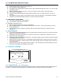
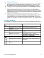
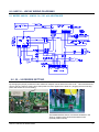
INSTALLATION AND OPERATING INSTRUCTIONS
I
INSTALLATION AND OPERATING INSTRUCTIONS
Hurlcon Gas Fired
Hydronic Heating Boiler
HW130 & HW160 ON/OFF Models
INSTALLATION AND
OPERATING INSTRUCTIONS
(External Models)
Melbourne: 03 9554 2275
Sydney: 02 9853 2100
Brisbane: 07 3308 5400
31/05/2010
Gold Coast: 07 5552 2600
Townsville: 07 4750 3100
Adelaide: 08 8152 7600
Perth: 08 9350 2600
[email protected]
www.hurlconheating.com.au
INDEX
1.1
2.0
MODELS AVAILABLE ...................................................................................................................................... 4
2.1
3.0
NOTICE TO INSTALLERS .................................................................................................................. 3
STANDARD EQUIPMENT .................................................................................................................. 4
INSTALLATION .................................................................................................................................................. 5
3.1
SAFETY RULES ................................................................................................................................... 5
3.2
GUIDE TO INSTALLATION ................................................................................................................ 6
3.3
CLEARANCES ...................................................................................................................................... 7
3.4
ELECTRICAL CONNECTION ............................................................................................................. 7
3.5
BOILER DIMENSIONS ........................................................................................................................ 8
3.6
INDOOR INSTALLATION .................................................................................................................... 8
3.7
HEATING PIPE SIZE & LAYOUT ...................................................................................................... 8
…………………………………………………………………………………………..…………………………9
3.8
SIZING OF PRESSURE VESSEL ...................................................................................................... 9
4.0
COMMISSIONING .............................................................................................................................................. 9
4.1
STARTING BOILER ............................................................................................................................. 9
4.2
TESTING BURNER PRESSURE ....................................................................................................... 9
…………………………………………………………………………………………………………………….10
4.3
FLOW SWITCH ................................................................................................................................... 10
4.4
5.0
GENUS IV 3 BUTTON CONTROLLER ............................................................................................. 10
OPERATING INSTRUCTIONS....................................................................................................................... 11
5.1
ENERGY SAVING TIPS .................................................................................................................... 11
5.2
MAINTENANCE .................................................................................................................................. 11
5.3
CONTROL SYSTEMS ....................................................................................................................... 11
6.0
……………………………………………………………………………………………………......12
…………………………………………………………………………………………..………………………..13
GAS CONVERSION ......................................................................................................................................... 13
6.1
BURNER CONVERSION ................................................................................................................................ 13
6.2
GAS PIPE SIZING TABLES .............................................................................................................. 14
7.0
TROUBLESHOOTING ..................................................................................................................................... 14
8.0
HW130 – HW160 WIRING DIAGRAMS........................................................................................................ 15
8.1
MODEL HW130 – HW160 On / Off with HEATSAVER .............................................................. 15
9.0
55 – 90 DEGREE SETTING............................................................................................................................ 15
10.0
ONE YEAR LIMITED WARRANTY ............................................................................................................... 16
11.0
MOUNTING INSTRUCTIONS......................................................................................................................... 17
HW130 –HW160 Hot Water Boilers
2
INTRODUCTION
Congratulations on your purchase of a Hurlcon HW130 - HW160 Series Hot Water Boiler. Correct installation and
service of your new heating system and correct chemical maintenance of the water will ensure years of service.
The HW130 - HW160 Series Boiler is a compact lightweight and efficient gas fired hot water boiler. It is equipped
with features that take advantage of new technology developed exclusively by Hurlcon.
The Hurlcon HW Boiler is a wall mounted induced draft atmospheric boiler with inbuilt flue for outdoor operation.
The power output is controlled by an integrated electronic controller to maintain the set point water temperature
over a wide load range. In addition, the Hurlcon HW Boiler is equipped with electronic ignition. The electronic
display tells at a glance the operational status of the boiler. The boiler application (radiator or floor coil) is
selectable via jumper settings on the Genus IV controller.
Note:
The appliance is not intended for use by young children or infirm person without supervision. Please ensure that
young children are supervised to ensure that they do not play with the appliance.
1.1 NOTICE TO INSTALLERS
This is a Wall Mounted - External – Hot Water Heating Boiler
For use with Natural Gas or LP Gas as per the attached data label.
The information below is given to assist the installer with the installation of this range of HW130 – HW160 Boilers.
Please read it carefully in order to make the installation as easy as possible and to ensure the system works well
and conforms to the necessary government regulations.
PLEASE READ THESE INSTRUCTIONS BEFORE STARTING THE INSTALLATION.
THIS APPLIANCE MUST BE INSTALLED BY AN AUTHORISED PERSON ONLY.
This boiler is to be installed and serviced to the requirements of the
Local Building, Gas, Water and Electricity Authorities.
These instructions are to be held by the owner / user after installation.
THIS APPLIANCE IS UNSUITABLE FOR USE AS A POOL HEATER
This appliance must be installed in accordance with the installation instructions, local gas fitting regulations, the
AGA Installation Code AS5601 / AG 601 and any other relevant statutory authorities.
Refer to data plate for details of gas type, gas consumption and burner pressure.
HW130 –HW160 Hot Water Boilers
3
2.0 MODELS AVAILABLE
Details
Height
Width
Depth
Gas input
Gas type
Nom output
Ignition system
Heat exchanger/burner
Boiler Thermostat
Pressure relief
Expansion vessel
Circulator
Hi limit Thermostat
Run on timer
Pressure reduction valve
Packed weight
Model
HW130
Model
HW160
905
520
651
325
105 (95) MJ
140 (135) MJ
Natural & (L P Gas)
24 (21) kW
35 (32) kW
Electronic Ignition
All copper/stainless steel
Electronic Genus IV (on/off) or SIT (modulating)
300kPa (3 Bar)
7 litre diaphragm (~60lt system)
In line Centrifugal Pump
o
99 C
Timed electronic
1 Bar pre-set
50kg
60kg
2.1 STANDARD EQUIPMENT
Electronic control including.
Set and flow temperature display.
Electronic ignition
Safety devices
Built in flow switch
Built in run on timer
Manual reset high limit
Built in pressure relief valve
Built to last
Double row heat exchanger made from one piece extruded finned copper tube
Stainless steel burners
Fully powder coated steel cabinet
Stainless steel flue terminal
Efficiency
Hot surface ignition
Induced draught combustion
Highly efficient stainless steel burners
Ease of installation
Fully plumbed ready to go, including circulating pump, expansion tank, pressure reduction valve & 1” flow
and return isolation valves.
All electrical pre wired including three pin power supply.
HW130 –HW160 Hot Water Boilers
4
3.0 INSTALLATION
THIS APPLIANCE MUST BE INSTALLED BY AN AUTHORISED PERSON.
Refer to boiler data plate for specifications of gas type, gas consumption, burner pressure and water pressure.
This appliance must be installed in accordance with local regulations and A.G.A. Installation Code AS5601 / AG
601.
The flow and return connections are located on the bottom of the boiler. The flow and return connections are
clearly marked and the connections are 1” BSP FI.
The Hurlcon Boiler is fitted with a built in flow switch and will not start unless full of water and the pump is
operating.
The Hurlcon Boiler incorporates a powered flue terminal suitable for outdoor installation. An indoor room sealed
model combined with co-axial flue kit for internal installation is available on request.
3.1 SAFETY RULES
For your safety – read before lighting
This appliance is equipped with an ignition device, which automatically lights the burner. Do not try to light the
burner by hand.
BEFORE OPERATING smell all around the appliance area for gas. Be sure to smell next to the floor because
some gas is heavier than air and will settle on the floor.
Safety
WHAT TO DO IF YOU SMELL GAS
Do not try to light any gas appliance.
Do not touch any electrical switch.
Turn off the gas supply at the gas meter.
Immediately call your gas supplier or licensed gas fitter.
NOTE. Some gases are heavier than air and it may be necessary to smell for leaks at floor level.
House keeping
Do not store or use flammable liquids or chemicals near this appliance.
Do not use aerosols in the vicinity of this gas appliance.
Keep this appliance free of debris.
WARNING:
Should overheating occur or the gas supply fail to shut off, turn off the manual gas control valve to the appliance.
Do not use this boiler if any part has been under water.
HW130 –HW160 Hot Water Boilers
5
3.2 GUIDE TO INSTALLATION
Location of Flue Terminals – An extract from AG 601
Minimum Clearances Required For Powered Flue, Balanced Flue Terminals or the Terminals of Room Sealed
Appliances.
a
j
h
j
openable
window
j
door
k
I
c
e
h
n
f
c
T
e
P
h
See note 3
d
g
d
M
T
b
g
k
T
See note 2
T = Flue terminal
I = Mechanical air inlet
M = Gas meter
P = Electricity meter
or fuse box
Shading indicates prohibited
areas for flue terminals
MIN. CLEARANCE
(mm)
A
B
C
D
E
F
G
H
I
K
N
Below eaves, balconies and other projections
Appliances up to 50 MJ/h input
Appliances over 50 MJ/h input
From the ground, above a balcony or other surface
From a return wall or external corner
From a gas meter (M)
From an electricity meter or fuse box (P)
From a drain pipe or soil pipe
Horizontally from any building structure (unless appliance approved
for closer installation) or obstruction facing a terminal
From any other flue terminal, cowl, or combustion air intake
Horizontally from an openable window, door, non-mechanical air inlet,
or any other opening into a building with the exception of sub-floor
ventilation
Appliances up to 150 MJ/h input
Appliances over 150 MJ/h but less than 200 MJ/h input
Appliances over 200 MJ/h input
All fan-assisted flue appliances, in direction of discharge
From a mechanical air inlet, including a spa blower
Vertically below an openable window, non-mechanical air inlet, or any
other
opening into a building with the exception of sub-floor ventilation
Space heaters
Up to 50 MJ/h
input
150
NOTES:
1
2
3
4
CLEARANCE ‘n’ (mm)
All other appliances
Up to 50 MJ/h
Over 50 MJ/h &
input
up 150 MJ/h
500
1000
200
300
300
300
1000
500
75
500
300
300
500
1500
1500
1000
See table
Over 150 MJ/h
input
1500
All distances are measured to the nearest part of the terminal.
Prohibited area below electricity meter or fuse box extends to ground level.
See Clause 5.13.6.6 for restrictions on a flue terminal under a covered area.
See Appendix J, Figures J1(a) and J2(a), for clearances required from a flue
terminal to an LP Gas cylinder. A flue terminal is considered to be a source of
ignition.
The above information is part of AG 601 FIGURE 5.3 as supplied by the AGA and is provided as an indication of
the correct clearances only. Please refer to the latest issue of AG 601.
HW130 –HW160 Hot Water Boilers
6
3.3 CLEARANCES
The boiler must not be installed against any combustible surface.
Clearances must comply with AS5601 / AG 601.
Clearances from surfaces are:
Front
Both sides
Above
Below
500mm
50mm
300mm
900mm
3.4 ELECTRICAL CONNECTION
The boiler is supplied with a standard 10 amp 3 pin plug for connection to a 240V 10 amp earthed GPO. The
boiler incorporates a 240/24 VAC transformer which supplies power to the control circuit only and must not be
used for any additional equipment. All equipment connected to mains power should be protected by an RCD
circuit breaker. The boiler has a 240 volt power supply for the pump electrical connection which incorporates the
pump run on feature. A terminal strip is provided for a 24 volt room thermostat.
If the supply cord is damaged, it must be replaced by the manufacturer or its service agent or a suitably qualified
person in order to avoid a hazard.
If the Hurlcon Genus IV central heating thermostat is used the 24volt room thermostat connection must be bridged.
Also unplug the spade connector from terminal IN-1 on the small heatsaver PC board in the electrical box and
make safe. This is the middle terminal on the top side. See page 16.
3.4.1 GAS CONNECTION
A ¾”BSP FI is provided for gas line connection. An approved manual shut off valve must be installed in the gas
fitting line before the boiler so that the gas can be turned off and the boiler removed for servicing if required. The
gas shut off valve should be sized the same as the gas fitting line to prevent excessive pressure drop in the gas
pipe.
The gas fitting line should be installed by an authorised person and comply with local regulations and A.G.A. code
AGS5601. The gas line from the meter will usually be of a larger size than the gas inlet connection. Therefore a
reduction to the boiler connection fitting will be necessary. The reduction should be as close to the boiler as
possible.
Before using the boiler, test all connections for gas leaks using soapy water.
The boiler gas valve has a built in pressure regulator with a ⅛” pressure test point provided. On starting the boiler,
a manometer must be used and burner pressure checked against the boiler data plate. The gas valve regulator
may need adjustment to correct manifold pressure. Incorrect burner pressure may void warranty.
HW130 –HW160 Hot Water Boilers
7
3.5 BOILER DIMENSIONS
3.6 INDOOR INSTALLATION
This boiler is designed for outdoor use only. If the HW130 - 160 Boiler is to be installed indoors, a dedicated
indoor model with special flue kit is available.
3.7 HEATING PIPE SIZE & LAYOUT
The flow & return connection sizes of 1”BSP on the boiler are not necessarily the correct pipe sizes for the
heating system. It is important that the pipe sizes are correctly calculated before installation.
Hurlcon recommend a two pipe system with the pipes sized according to the flow requirements and length
of runs with a maximum water velocity of 1.5 M/s.
Reference The Institute of Plumbing Australia. - “SELECTION & SIZING OF COPPER TUBES FOR
PIPING SYSTEMS”.
Nominal flow capacities
Model
Output
130
24 kW
160
35 kW
Flow rates
0.38 l/s
0.53 l/s
HW130 –HW160 Hot Water Boilers
DT
15 oC
15 oC
pd
8 kPa
14 kPa
min Pipe dia
20 mm
25 mm
F & R length
6.0 m
4.5 m
8
Typical two pipe system
Radiator/Heat emitter
Flow
Flow
Flow
Hydronic Boiler
Return
Bypass
valve
Notes
1. An automatic heating bypass valve should be fitted to maintain adequate flow rate through the boiler when
thermostatic valves are fitted and or when the majority of radiators are required to be turned off for long
periods of time.
2. Any pipe work that is in an unheated area such as under the floor or in the ceiling space should be suitably
insulated to prevent heat loss and possible freezing of the pipes.
3. The pipe work should be graded to facilitate the elimination of air at the highest point and the draining of
the system at the lowest point. Provide air bleeds and drains at these points.
3.8 SIZING OF PRESSURE VESSEL
Item
If the total water capacity of the heating system is greater
than 60 litres then an additional pressure vessel should be
fitted. An approximate figure can be calculated from the
following table. An additional tank can be fitted at a
convenient location on the system if required.
Therma rad Radiators
Thermaboard single
Thermaboard double
Copper tube 25 mm
Copper tube 20 mm
Copper tube 15 mm
Capacity
litres
0.70
0.22
0.44
0.44
0.23
0.10
per
kW
metre
metre
metre
metre
metre
4.0 COMMISSIONING
4.1 STARTING BOILER
Fill system with water and purge all air from system and pump.
Purge gas line of any air and wait five minutes for gas to clear.
Plug three pin plug into a suitable power point and switch on. Digital controller should now operate and
indicate water temperature.
Pump should start, the flow symbol should be displayed.
Turn controller switch ON.
After a few seconds, the burner should ignite. (Do not light by any other means.)
If the burner fails to light, check flow indicator is on. Turn controller switch OFF for 5 seconds then ON to
reset ignition system. (Trouble shooting page 15.)
Allow boiler to run. Check there are no leaks and there is flow to all of the system.
4.2 TESTING BURNER PRESSURE
Set up manometer
Turn boiler “OFF”.
Open lower front door.
Remove screw from ⅛” brass test point located on outlet side of gas valve.
Connect manometer tube to test point
Turn boiler “ON” and wait for main burner to ignite.
Once main burner has ignited, the manometer must indicate the nominal burner pressure listed below.
To adjust gas valve regulator, remove regulator adjustment cap and, using a screwdriver, turn plastic bush
clockwise to increase, anti-clockwise to decrease burner pressure.
When correct pressure is set turn boiler off.
Refit test point screw, fibre washer and regulator adjustment cap.
Check all gas connections are tight and not leaking.
Close front door.
HW130 –HW160 Hot Water Boilers
9
Maximum inlet gas pressure is:
Natural Gas
3.5 kPa
ULPG
3.5 kPa
Nominal burner pressure is:
Natural Gas kPa
ULP Gas kPa
HW130
0.92
2.00
HW160
0.90
2.00
Gas Specifications
Natural Gas
Capacity input MJ/h
Output kW/h
Number of Burners
Injector Diameter of Main Burners
Burner Pressure (kPa)
Hourly Gas Consumption per Burner MJ/h
ULPG
HW130
105
24
14
1.3mm
0.92
7.5
HW130
Capacity input MJ/h
Output kW/h
Number of Burners
Injector Diameter of Main Burners
Burner Pressure (kPa)
Hourly Gas Consumption per Burner MJ/h
95
21
14
0.79mm
2.0
6.75
HW160
140
35
20
1.25mm
0.90
7.5
HW160
135
32
20
0.79mm
2.0
6.78
4.3 FLOW SWITCH
The Hurlcon Boiler has an inbuilt flow switch which allows the burner to operate only when the system is
full of water and the circulating pump is operating. NOTE: The installed flow switch has no user
adjustments.
Air in the system may stop the boiler from lighting.
4.4 GENUS IV 3 BUTTON CONTROLLER
90° or 55° operation. HW series boilers are factory default 90°. For floor heat applications the boiler can
be selected for 55° max setpoint by a jumper on the PCB. (See page 16).
Hurlcon Genus IV room thermostat. If a Hurlcon Genus IV room thermostat is fitted the Genus boiler
control will ‘learn’ automatically when powered up, after approx 1 minute. If the thermostat is disconnected
or loses communication F5 fault will be displayed and the boiler will shut down after 3 minutes. To change
thermostat type see table below. The thermostat selector switch located on the „heatsaver‟ PCB also
needs to be set to the correct position for pump run on. See page 16, 90 degree operation.
Switching differential. The temperature switching differential can be adjusted to stop short cycling. See
table below for appropriate codes. (Default 5°.)
°F or °C. The display can be toggled between Celsius and Fahrenheit. See table below for codes.
(Default °C.)
With the unit switched off, press and hold the on/off button then press the following.
Degrees C
Degrees F
1
U
U
2
D
D
Button presses
3
D
D
4
D
U
Genus IV thermostat
Standard thermostat
U
U
D
D
U
U
D
U
5 ° differential
10 ° differential
15 ° differential
20 ° differential
D
D
D
D
D
U
U
D
U
D
U
D
HW130 –HW160 Hot Water Boilers
D
D
D
U
U = warm button
D = cool button
10
5.0 OPERATING INSTRUCTIONS
STOP! Read the safety rules on page 6 section 3.1.
Turn off electric power to appliance.
This appliance is equipped with an ignition device, which automatically lights the burner. Do not try to light
the burner by hand.
Wait five minutes to clear out any gas. If you then smell gas, STOP! Refer to instructions above.
Turn on power to appliance.
Set thermostat to desired setting and press ON/OFF switch to ON. The boiler will ignite in around 10
seconds
If the appliance will not operate, press ON/OFF switch to OFF then ON again. If the appliance still does
not ignite, check trouble shooting on page 14 or call your service technician.
TO TURN GAS OFF TO APPLIANCE
Turn off all electrical power to the appliance.
Turn off gas tap in gas line prior to boiler.
5.1 ENERGY SAVING TIPS
During extended periods of non use, turn the boiler off.
Set up a regular program of preventative maintenance for the boiler. Check heat exchanger, controls,
burner operation etc.
For areas where there is a danger of freezing, water should circulate through your boiler even if the
heating is off.
5.2 MAINTENANCE
It is recommended that the following items are professionally checked at least every six months and at the
beginning of every heating season.
Examine the flue outlet or termination cowl. Make sure there are no obstructions to the flow of air to, or
flue products from, the appliance.
Visually check the main burner and pilot flames. If the flame appears yellow, the burner should be cleaned
by a qualified service technician.
Keep the boiler area clear and free of combustibles and flammable liquids. Chlorine should not be stored
in the vicinity of the boiler. Chlorine vapours, when drawn through a boiler, can rapidly cause corrosion of
the heat exchanger.
Keep the boiler area free from garden refuse and debris. This will help prevent insects nesting in the unit
and ensure extended life and reliability of your boiler.
5.3 CONTROL SYSTEMS
ON/OFF
WARM
<
○
>
HURLCON
COOL
HURLCON
5.3.1 DESCRIPTION – On / Off models
The sophisticated digital thermostat provides temperature read out, set point temperature and operating status of
the boiler. The electronic display indicates the operational status of the boiler and any fault conditions.
HW130 –HW160 Hot Water Boilers
11
5.3.2 TEMPERATURE DISPLAY
The temperature display indicates water temperature in the outlet (flow) of the boiler. Therefore the pump
must be operating for an accurate water temperature to be displayed.
Water temperature can be set between 55˚C to 90˚C. (35˚C to 55˚C floor heat). To select your desired
water temperature press the up or down button repeatedly until the desired temperature is reached.
To prevent rapid cycling of the boiler, the thermostat has an inbuilt time delay which prevents the boiler
from turning on for two minutes after the set point has been reached. If the time delay is activated, the
symbol “L” will be displayed. This is part of normal operation.
The thermostat can be set to temperatures between 55˚C to 90˚C. (35˚C to 55˚C floor heat). It also
incorporates several safety features including a 100˚C high limit function to prevent overheating. On
simultaneous shut down of the circulating pump and boiler, the water within the boiler may exceed the set
temperature for a short period. If the pump and boiler are restarted during this period, the thermostat will
go into a standby mode and prevent the boiler from relighting until the temperature within the boiler has
dropped below the set temperature.
Should the thermostat fail to stop the boiler at the set point or at 100˚C, there is a manual reset
temperature limiting safety device designed to lock the boiler out and prevent further heating. A lock out
condition is indicated by the symbols F1 or F2 on the display. To reset a lock out condition, turn the
controller off for five seconds. An F2 condition will first require the mechanical safety device to be reset. To
do this, remove the top front access panel and locate the high limit thermostat at the outlet of the heat
exchanger, press the red button. If the boiler has cooled sufficiently, a positive “click” should be heard and
felt.
5.3.3 FAULT INDICATION
Under fault conditions the thermostat display will indicate a set of alpha numeric symbols to indicate the status of
the boiler. The meaning of each symbol and action to be taken are listed as follows:
SYMBOL
Temp
Display
F0
F1
F2
F5
L
MEANING
Unit has power.
ACTION
No action
Boiler locked off, thermistor wire is
disconnected or water at 0 C (freeze
conditions).
Thermostat reads greater than 100 C
or thermistor short circuited.
Mechanical Hi Limit greater than 99 C.
If water temperature reads greater than 0 C, turn
off/on if problem persists phone for service.
No communication to indoor
thermostat.
Boiler locked out on time delay
Pump operating & sufficient water flow
to operate boiler
Allow water to cool, turn boiler off then on again.
Allow water to cool, reset Hi Limit, turn boiler off then
on again.
Check connections. Check setting code.
No action. Boiler will delay for 2 minutes
Automatically reset after time delay. Or switch off
then on again for immediate ignition.
No action.
Thermostat calling for heat operating.
No action, boiler electronic ignition should ignite in a
few seconds.
Burner system has ignited and is
operating.
No action.
HW130 –HW160 Hot Water Boilers
12
OPERATION
Sequence of events once the boiler has been correctly installed with the room thermostat and burner turned off.
Event
Turn on electrical power to the boiler
Turn on room thermostat or
Turn controller on.
Water flow reaches set temperature.
Water flow temperature falls 5 C
(adjustable) below set temperature.
Water flow temperature reaches 99 C
Controller turned off
Room thermostat switches off
Room thermostat switches on
Water flow stopped by external control
Water flow is reinstated
Result
Controller powers up and completes test procedure.
Pump starts up. Flow indicator on.
Ignition sequence begins; checks water flow, high limit and flow
temperature against set temperature.
Burner lights.
Burner indicator on.
Burner turns off.
Burner relights.
Burner indicator on.
High limit switch opens, burner shuts down. Pump continues to
run.
Burner shuts down, pump continues to run.
Burner shuts down; pump continues to run until water
temperature drops to 20˚C below setpoint.
Pump restarts, burner ignites.
Flow switch de-activates, burner turns off and pump continues
to run.
Flow indicator off.
Flow switch reactivates, burner re ignites.
Flow indicator on.
6.0 GAS CONVERSION
6.1
BURNER CONVERSION
1.
2.
3.
4.
5.
6.
7.
8.
9.
10.
11.
12.
13.
14.
15.
16.
17.
18.
19.
Turn off and disconnect gas supply to unit.
Turn off power supply to pump and heater.
Remove front access doors
Disconnect flexible s/steel gas supply tube from burner manifold.
Remove burner top bracket. Remove Right Hand Side Shield. Remove left hand side shield.
Remove burner lower shield.
Remove the four Phillips head screws securing the burner at the end of the manifold tube to combustion
chamber support angles.
Slide burner out.
Remove burner injectors and replace with desired gas type injectors.
Remove regulator screw cap from top of gas valve
Turn plastic plug anti-clockwise until fully removed and withdraw spring.
Insert spring for desired gas type and re-install plastic plug.
Re-install burner assembly and refit panels.
Reconnect the gas supply.
Modify / replace data labels and gas valve type label.
Check gas system for leaks.
Commence lighting procedure as described above.
Adjust burner pressure as described above.
NOTE: It is imperative that all shields are refitted for correct burner operation and combustion, incorrect reassembly could void warranty
HW130
GAS TYPE
NATURAL
ULPG
INJECTOR SIZE
1.30 mm
0.79 mm
BURNER PRESSURE
0.92 kPa
2.00 kPa
HW 160
GAS TYPE
NATURAL
ULPG
INJECTOR SIZE
1.25 mm
0.79 mm
BURNER PRESSURE
0.90 kPa
2.00 kPa
HW130 –HW160 Hot Water Boilers
13
6.2
GAS PIPE SIZING TABLES
Natural gas at 1.13 kPa gas meter pressure
VICTORIA
Maximum run of copper pipe with average number of fittings
Model
20 mm
25 mm
32 mm
HW130
4m
25 m
90 m
HW160
2m
14 m
50 m
40 mm
260 m
140 m
1.25 kPa gas meter pressure
S.A., W.A., some areas N.S.W.
Maximum run of copper pipe with average number of fittings
Model
20 mm
25 mm
32 mm
40 mm
HW130
18 m
85 m
300 m
320 m
HW160
10 m
45 m
160 m
320 m
50 mm
320 m
320 m
50 mm
-
2.75 kPa gas meter pressure
N.S.W. some areas, some new areas of Victoria.
Maximum run of copper pipe with average number of fittings
Model
15 mm
20 mm
25 mm
32 mm
HW130
12 m
100 m
320 +m
HW160
8m
65 m
260 m
320 +m
NO allowance has been made for other appliances connected to the gas main. This information is supplied as an
indication of the capacities only. Refer to the latest issue of AG601 for full details.
7.0 TROUBLESHOOTING
BOILER WILL NOT LIGHT
Possible cause
Automatic ignition system fails
Pump not running
Pump air locked
Flow switch open
Defective gas control
Thermostat turned off
Set temperature lower than water temperature
Water too hot-fault condition displayed
High Limit Thermostat open
Insufficient water flow
BOILER MAKING KNOCKING NOISES
Possible cause
Boiler operating after pump has shut off
Heat exchanger scaled
Remedy
Check water flow light indicator.
Check pump and flow switch
Air bleed system & pump bearing
Check continuity
Shut off gas supply and call for service
Turn on
Increase set temperature
Refer to fault indication table
Reset
Check for too many valves turned off
Remedy
Shut off gas supply and call for service
Shut off gas supply and call for service
If the boiler cannot be made to perform correctly, please contact the Hurlcon Service Office closest to you.
For
VICTORIA:
NEW SOUTH WALES:
QUEENSLAND:
SOUTH AUSTRALIA
WESTERN AUSTRALIA
Phone (03) 9554 2275
Phone (02) 9853 2100
Phone (07) 3308 5400
Phone (08) 8152 7600
Phone (08) 9350 2600
For all other areas, please contact our Victorian office.
HW130 –HW160 Hot Water Boilers
14
8.0 HW130 – HW160 WIRING DIAGRAMS
8.1 MODEL HW130 – HW160 On / Off with HEATSAVER
9.0 55 – 90 DEGREE SETTING
By changing the jumper position the boiler maximum setpoint can be altered from 90° to 55°. This should be done
prior to start up, however if this is done after power has been applied to the boiler un- plugging and reconnecting
power will ensure the correct setting.
Thermostat selector switch. This switch should be in the
„Hurlcon‟ position if the Genus thermostat is used.
(Normal position shown)
HW130 –HW160 Hot Water Boilers
15
10.0 ONE YEAR LIMITED WARRANTY
GENERAL CONDITIONS
Hurlcon cover your boiler with a limited 1 year warranty against defective materials and workmanship from the date
of purchase (plus 30 days to allow for installation). The heat exchanger, burner and cabinet are covered by a five
year limited warranty (plus 30 days to allow for installation). Proof of purchase date must be provided in order to
substantiate warranty claim.
The warranty includes 12 months in field labour costs where the boiler is installed in a capital city metropolitan
area. Labour charges apply to boilers installed outside of these areas. Any costs for transport of faulty or
replacement parts, removal or reinstallation are the owner‟s responsibility.
Hurlcon assumes no liability for consequential damages of any kind.
Like your motor vehicle, your new boiler requires periodic service and maintenance to keep it operating in top
condition and at maximum efficiency. An annual service by one of our qualified service technicians is highly
recommended.
LIMITATIONS
All warranties only apply if the boiler is installed and operated in complete compliance with the installation and
operating instructions. The warranty shall not apply to any boilers or parts that have been subject to accident,
negligence, alteration, abuse or misuse.
ADDITIONAL WARRANTY EXCLUSIONS:
This warranty does not cover failures or malfunctions resulting from:
Failure to properly install, operate or maintain the boiler in accordance with our printed instructions
provided.
Abuse, alteration, accident, fire, flood and the like. Examples of misuse or neglect include, but are not
limited to, physical damage from external force, not following installation instructions, leaving door off for
extended periods of time, inappropriate application of the boiler, etc.
Scaling, freezing, or other conditions causing an inadequate water circulation.
Incorrect gas pressure or gas supply.
Incorrect or excessive flow rate of water.
Failing to correctly bleed water system of air.
Chemical contamination of combustion air or use of chemical additives to the water.
Printed Circuit Boards: This item is warranted against all claims except for power surges, lightening
strikes, wilful damage or water damage
No person is authorised to make any warranties on Hurlcon‟s behalf. To place a service call, contact your nearest
Hurlcon office.
HW130 –HW160 Hot Water Boilers
16
11.0 MOUNTING INSTRUCTIONS
Mark the fixing hole locations for the top mounting bracket at the desired height. Mark the fixing hole locations for
the bottom mounting bracket with the holes at 820mm centres.
Securely fix the top and bottom mounting bracket (WS0901) (WS0902) to the wall. Lift the boiler over the bracket
sliding the bracket lugs into the slots in the boiler.
HW130 –HW160 Hot Water Boilers
17
HW130 –HW160 Hot Water Boilers
18
HW130 –HW160 Hot Water Boilers
19
INSTALLATION AND OPERATING INSTRUCTIONS
I
INSTALLATION AND OPERATING INSTRUCTIONS
HURLCON HEATING Pty. Limited. A.B.N. 97 007 284 504
www.hurlconheating.com.au email: [email protected]
Information and specifications subject to change without notice.
Victoria:
Ph: (03) 9554 2275
Fax: (03) 9554 2272
New South Wales:
Ph: (02) 9853 2100
Fax: (02) 98532170
Queensland:
Ph: (07) 3308 5400
Fax: (07) 3308 5470
HW130 –HW160 Hot Water Boilers
South Australia:
Ph: (08) 8152 7600
Fax: (08) 8152 7670
Western Australia:
Ph: (08) 9350 2600
Fax: (08) 9350 2670
Gold Coast:
Ph: (07) 5552 2600
Fax: (07) 5552 2670
Townsville:
Ph: (07) 4750 3100
Fax: (07) 4750 3170
20