1
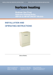
Genus III Pool and
Spa Controller
INSTALLATION & OPERATING INSTRUCTIONS
AstralPool Australia Pty. Limited. A.B.N. 97 007 284 504
Information and specifications subject to change without notice.
Melbourne:
Ph: (03) 8796 8600
Fax: (03) 8796 8670
Sydney:
Ph: (02) 9853 2100
Fax: (02) 9853 2170
Rev 186-0804
Brisbane:
Ph: (07) 3308 5400
Fax: (07) 3308 5470
Gold Coast
Ph: (07) 5552 2600
Fax: (07) 5552 2670
Townsville:
Ph: (07) 4750 3100
Fax: (07) 4750 3170
Adelaide:
Ph: (08) 8152 7600
Fax: (08) 8152 7670
Perth:
Ph: (08) 9350 2600
Fax: (08) 9350 2670
INDEX
OPERATION INSTRUCTIONS
Introduction........................................................................................................3
Components .......................................................................................................3
Timer Handset....................................................................................................3
Operation............................................................................................................3
Setting the Clock............................................................................................. 4
Setting a Timer................................................................................................ 4
Setting Multiple Timers .................................................................................. 4
Adjusting Heater Temperature........................................................................ 4
No Timer Handset..............................................................................................4
Pump Override Switch.......................................................................................5
LCD Display ......................................................................................................5
Fault Indication ..................................................................................................5
INSTALLATION INSTRUCTIONS
Power Supply Module Mounting.......................................................................6
Heater Connections............................................................................................6
Temperature Sensor ...........................................................................................7
Handset Connections .........................................................................................7
Chlorinator Connection......................................................................................8
Genus Thermostat Settings ................................................................................9
Connection Summary.........................................................................................9
Valve Connection and Configuration ..............................................................10
Warranty ..........................................................................................................11
Genus III Remote Control User Manual
Page 2
INTRODUCTION
Congratulations! You have purchased a high quality Genus III Pool and Spa Equipment Centre.
Please read the instructions carefully and your purchase will provide you with years of trouble
free use.
COMPONENTS INCLUDED
1
1
1
1
1
1
1
x
x
x
x
x
x
x
Power Module / Equipment Centre
Console / Touchpad
10m Cable for Heater Connection
Installation and Operation Manual
Set of mounting Screws
50mm PVC Temperature Sensing Coupling
Temperature Sensor Lead
TIMER HANDSET
The Timer Handset will display the status of the Heater as well as that of the accessories
operated by the Control Unit. The Timer Handset has a Clock and 4 inbuilt timers which can be
set to turn the pump on and off in multiples of 15 minutes. You can use all of the timers, only a
few or none at all.
OPERATION
Your Timer Handset has 7 functions which are explained below;
On/Off
Turns the Heater On or Off
Warm
Increases the Pool/Spa Set Temperature
Cool
Decrease the Pool/Spa Set Temperature
Pump
Turns the Pump On or Off
Blower
Turns Blower On or Off.
Aux 2:
Turns Auxiliary 2 On or Off or, where enabled,
or
or
Pool/Spa
Changes between Pool/Spa Setting
(VX Model chlorinators installed will automatically change
between Pool and Spa Chlorine Output setting also)
Aux 3
Turns Auxiliary 3 On or Off
Note: Set point temperature of Heater will only be displayed if Heater is connected to system.
Genus III Remote Control User Manual
Page 3
SETTING THE CLOCK
1. Ensure that the Heater On/Off button is in the ‘Off’ position.
2. While holding the “Warm” button down press the “Cool” button momentarily. The
screen will display the time.
3. Set the hour using the Warm and Cool buttons. Once the hour has been set push the
On/Off button to set the minutes
4. Set the minute using the Warm and Cool buttons. Once the minute has been set push the
On/Off button to confirm the time set.
5. Press the Warm button to return to the main screen.
SETTING A TIMER
1. Ensure that the Heater On/Off button is in the ‘Off’ position.
2. While holding Cool button down press the Warm button momentarily.
3. Set the desired pump start time using the Warm and Cool buttons then press the On/Off
button to confirm.
4. Set the desired time for the pump to turn off. Then press the On/Off button to confirm.
5. Repeat steps 3 to 4 to set multiple timers the time.
6. Press the On/Off button until the screen displays DONE. Press the Warm button to
return to the main screen.
ADJUSTING THE TEMPERATURE (Only when heater is connected)
1. Press the On/Off buton until the word ‘ON’ appears on the display that the Heater.
2. Using the Warm and Cool buttons, press until the desired temperature is set, the set
temperature can be seen on the display.
3. Different temperatures can be set for both the Pool and the Spa.
4. Control system will now send ignition signal to heater.
PUMP TIMER OVERRIDE SWITCH
A pump timer override switch is located on the front of the control unit in case you should
require manual control of the pump for the purposes of backwashing, maintenance, etc.
This switch should be in the “Auto” position for normal remote and timer control.
The “On” position turns the pump on regardless of the timer and remote control settings.
The “Off” position prevents the pump operating regardless of the timer and remote control
settings.
NO TIMER HANDSET
The No Timer Handset is used in conjunction with the Timer Handset. It gives control of the
Heater and Control Unit and displays the operating status of both, but no timers can set be set
with this handset and there is no clock.
Genus III Remote Control User Manual
Page 4
LCD DISPLAY
The Handset (with or without timer) displays a set of alpha numeric symbols to
indicate the operating status of the Heater and Control Unit.
2
Pump Timer/s are activated.
No action
Pump is turned on
No action
Blower turned on
No action
Auxiliary 2 turned on
No action
Note: For Pool/Spa Button Option, number 2 is not displayed
3
Auxiliary 3 turned on
No action
Thermostat calling for heat.
Electronic Ignition operating.
No action, heater
should ignite in a
few seconds.
FAULT INDICATION
Under fault conditions, the thermostat display will indicate a set of alpha numeric
symbols to indicate the status of the heater. The meaning of each symbol and action to
be taken are listed as follows:
SYMBOL
MEANING
ACTION
Back Lighting
Unit has power
No action
Set Temp Display
System has heater
connected
No action
L
Heater locked out on time
delay for 2 minutes.
No action. Heater
will automatically reset
after time delay. Or switch
off then on again for
immediate ignition.
Genus III Remote Control User Manual
Page 5
POOL AND SPA EQUIPMENT CENTRE
INSTALLATION
WARNING!
The Genus IV remote system is connected by 6 wire flat cable with RJ12 connectors.
The Cable with RJ12 Connection to the Pool Heater and Handset must be installed
before power is supplied to the Power Supply Module. The combined load of
equipment operated must not exceed 40 Amps. The Power Supply Module must be
hard wired by a licensed electrician. To avoid a safety hazard, the supply cord if
damaged, must only be replaced by Hurlcon, or its service agent or a suitably
qualified person. For products with fixed wiring, a means of disconnection must be
provided in the fixed wiring. The Pool and Spa Equipment Centre is not intended
for use by young children or infirm persons without supervision. Please ensure that
young children are supervised to ensure that they do not play with the Pool and Spa
Equipment Centre.
POWER SUPPLY MODULE MOUNTING BRACKET
The Power Supply Module comes with a wall mounting bracket so it can be securely fixed to
any wall. The Power Supply Module must be hung where it is protected from direct sunlight
and rain (IPX3).
1.
2.
3.
4.
Remove wall mounting bracket from Power Supply Module by un-doing the screw
located near the pump socket.
Screw mounting Bracket to wall.
Engage the Power Supply Module’s top rear edge with the joggled section on the
top of the bracket.
Align the screw hole in the underside of the Power Supply Module with the hole in
the lower face of the mounting bracket and secure.
HEATER CONNECTION (Voltage Free Contacts)
(This system is not to be used in conjunction with any
Hurlcon Genus model heater)
1. Run a 2 core cable between the Power Supply module the heater.
2. Strip the wires at the Power Supply Module and connect one to each of the spring
loaded terminals.
3. At the Heater end of the cable, strip the wires back to 2 single cables.
4. At the Heater, locate the Pressure Switch and remove one of the wires.
5. Connect the first wire to the spare terminal on the pressure switch.
6. Connect the other wire to the wire that was once connected to the pressure switch.
(Note: The power supply through the Pressure Switch must not exceed 24VAC)
7. Turn the heater ON and to its maximum temperature setting.
HEATER CONNECTION (15Amp Electric Heater)
1. Plug in Electric Heater into 15amp socket labelled Heater.
2. Turn electric and set thermostat to maximum setting.
3. Electric heater will now turn on and off when water temperature falls below set point
show on Genus III Console
Genus III Remote Control User Manual
Page 6
TEMPERATURE SENSOR/COUPLING
1. Plumb in 50mm coupling in plumbing of equipment prior to water flow entering the
heater. For installations where there is no heater, installation of coupling can be
anywhere in system.
2. Temperature sensor must be inserted in Sensor Pocket which is located in 50mm
coupling. Secure sensor into position using a Neutral Cure Silicone and insulate cable
using a protective sleeve if sensor is exposed to harsh climatic elements.
3. Other end of temperature sensor must be plugged in to Genus III Power Module.
HANDSET CONNECTION
The method of installation will depend on the surface the Remote Control is intended to be
fixed to. Below is a guide to where each method would be most suitable.
The Handset is supplied with two types on mounting systems. Surface Mount and Flush Mount
Kits. The flush mount kit is attached during shipping. Unclip the Flush Mount cover of the
Handset and feed the 6 wire flat cable through the square hole in the back cover on the
mounting bracket selected for installation. Connect it to the RJ12 socket on the PCB. If the
Surface mount bracket is used, attach this to the wall using appropriate fixing screws, once RJ
12 Cable is attached clip the console into place. If the Surface Mount Bracket is used, feed the
cable under the off-set plastic tabs. Then attach the RJ 12 Cable and clip the console into place.
The Remote Control is supplied with specially designed double sided tape for flush mounting.
The tape is designed for installations with flat surfaces, where maximum strength is required
and where removal will not damage the surface and is suitable for indoor and outdoor
installations. Note – when installing into plaster or similar use the plaster wall mount bracket.
See below for installation instructions.
When flush mounting, the Remote Control can also be installed using silicone sealant for
surfaces that are un-even.
The cut out size for flush mounting is 178mm x 67mm.
If Surface Mounted, Tape is to be removed before installation
The correct Touchpad label needs to be fitted to suit the setup that you require. As a default,
the Genus system is set-up as a 4 function system with no Pool/Spa valve actuation, therefore
the label with Aux 3 would need to be fitted. If reconfigured to operate with valve actuators,
the label with Pool/Spa will need to be fitted.
PLASTER WALL BRACKET INSTALLATION
4. Cut hole in plaster 179mm x 67mm
5. Using mount bracket as a guide drill 2 screw holes 4mm diameter.
6. Feed RJ12 cable through left side square cutout. Push bracket back into hole and bend
the side tabs behind the plaster.
7. Screw 2 off 6# Countersunk screws (supplied) through the side holes into the side tabs.
The tabs will tighten behind the plaster.
Genus III Remote Control User Manual
Page 7
8. Remove the back cover of the Flush mount style heater remote. Feed the RJ12 cable
through the back cover and fix cover to the mounting plate (2 off 6# selftapping
screws).
9. Do not remove the backing paper of the tape gasket. Connect cable to RJ12 connection
on circuit board and push panel back into bracket. Panel will clip into the fixed back
cover.
10. For removal, using a flat screw driver, insert the screw driver between the front panel
and the wall bracket. The front panel will unclip with a slight leaver action.
CONNECTION TO HURLCON SALT CHLORINATORS
The VX Chlorinator control needs to be connected to the equipment centre via a remote cable.
To connect the cable from the Chlorinator Control to the equipment centre, do the following:
1. Turn off the mains supply to the equipment centre.
2. Plug one end of the RJ12 cable into the RJ12 socket that can be found on the underside
of the Power Supply Module. (Cable not supplied)
3. The other end of the cable must be plugged into the VX ‘S’ model chlorinator.
4. Connect the chlorinator mains plug into the pump outlet of the Power Supply Module.
5. Plug the pump into the power socket located on the underside of the VX chlorinator.
6. Set the Pump override switch to the Off position.
7. Turn on the mains to the Equipment centre.
8. Whilst holding down the Superchlorinate and Power level up buttons, turn the Pump
override switch to ON. The Chlorinator should indicate a S for system after the model
setting.
NOTE: The pump Override switch should no longer be used in the “Auto” Position. It
should be left in the On position for normal operation and off for maintenance.
.
INTERFACE FOR NON HURLCON SALT CHLORINATORS (OPTION)
1. Connect the male 4 pin plug into one of the female 4 pin sockets of the Power Supply
Module.
2. Cut the sense wire on Salt Chlorinator and crimp in blue wires from Salt Chlorinator
Interface.
Note: If Chlorinator output is disabled when in Pool mode, swap white and red leads
inside Salt Chlorinator Interface.
Genus III Remote Control User Manual
Page 8
GENUS – THERMOSTAT SETTINGS
The Genus IV control needs to be correctly configured to suit the setup that you require. As a
default, it is set-up as a 4 function system with no Pool/Spa valve actuation and assumes that an
external type heater is connected. To reconfigure, follow the procedure below:
While the Heater Thermostat displays “Off”, hold the “On/Off” button and press the
following combination:
Configuration
Button Sequence
4 Function Mode(default)
or
Pool/Spa + 3 Function Mode
Warm, Cool, Warm, Cool
or
Warm, Cool, Warm, Warm
Thermostat Displays
Briefly
RLY - AUX 2
or
RLY – POOL SPA OFF
Heater Installed & Connected
or
No Heater
Down, Down, Down, Up
or
Up, Up, Up, Down
Software Version number
followed by HP or
“Set temp will not display”
Temperatures can be displayed in either Celsius or Fahrenheit. Again
While the Heater Thermostat displays “Off”, hold the “On/Off” button and press the
following combination:
“Warm, Cool, Cool, Cool” →
“Warm, Cool, Cool, Warm” →
Degree Celsius (Default Setting)
Degree Fahrenheit
CONFIGURATION SUMMARY
System
Heater
Pool/Spa Remote
Heater
4 function Remote
Heater
Pool/Spa Remote
with
Hurlcon Chlorinator
Heater
4 function Remote
with
Hurlcon Chlorinator
Genus III Remote Control User Manual
Heater Setting - hold
Chlorinator
down On/Off Button (whilst
in off mode and press)
Warm, Cool. Warm, Warm
- power up with
following
buttons pressed
N/A
Warm, Cool. Warm, Cool
N/A
Warm, Cool. Warm, Warm
Superchlorinate
and Chlorine
power level up
Warm, Cool. Warm, Cool
Superchlorinate
and Chlorine
power level up
Page 9
Valve Connection and Configuration
Valve
Configuration
Cam
Adjustment
RETURN SIDE
Moving
Cam this
way
adds some
return water
to Spa
SPA
RETURN
POOL
RETURN
RETURN
RETURN SIDE
POOL
RETURN
SPA
RETURN
Moving
Cam this
way
adds some
return water
to Spa
RETURN
SUCTION SIDE
SPA
SUCTION
POOL
SUCTION
PUMP
SUCTION
SUCTION SIDE
SPA
SUCTION
POOL
SUCTION
PUMP
SUCTION
Genus III Remote Control User Manual
Page 10
WARRANTY
Your Function Remote with Temperature Adjustment is covered by a limited 12 month
warranty against defective parts and faulty workmanship (plus 30 days to allow for
installation).
To make a warranty claim you must return your Pool & Spa Equipment Centre to Hurlcon’s
factory freight prepaid and Hurlcon will repair or replace it (at its option) and return it to you.
Should a fault occur, call Hurlcon or an Authorised Hurlcon Service Agent. There are no user
serviceable parts. Always turn off and disconnect power supply when removing Power Supply
Module.
Limitations
All warranties only apply if the equipment is installed and operated in complete compliance
with the installation and operating instructions.
Specific limitations and exclusions include but are not limited to, water ingress into Power
Supply Module and Remote Control, excessive appliance current load on any one or number of
power outlets, misuse or abuse whether intentional or accidental.
Hurlcon assumes no liability for consequential damages of any kind. In field labour warranty
is applicable in capital city metropolitan areas and within a 20 km radius of Hurlcon Authorised
Service Agents. Should you request a warranty service call and the problem is diagnosed as
non-warrantable, you will be charged for a diagnostic service call plus any parts and labour
required to repair the Multi-Function Remote Controller. No person is authorised to make any
representations on behalf of Hurlcon.
Commercial Installation
On Commercial Installations, such as health clubs, motels/hotels and hydrotherapy facilities,
parts and in field labour warranty (in capital city metropolitan areas and within a 20 km radius
of Hurlcon Authorised Service Agents) is 6 months from the date of purchase plus 30 days to
allow for installation.
AstralPool Australia Pty. Limited
Melbourne:
Ph: (03) 8796 8600
Fax: (03) 8796 8670
Sydney:
Ph: (02) 9853 2100
Fax: (02) 9853 2170
Brisbane:
Ph: (07) 3308 5400
Fax: (07) 3308 5470
Gold Coast
Ph: (07) 5552 2600
Fax: (07) 5552 2670
Townsville:
Ph: (07) 4750 3100
Fax: (07) 4750 3170
Adelaide:
Ph: (08) 8152 7600
Fax: (08) 8152 7670
Perth:
Ph: (08) 9350 2600
Fax: (08) 9350 2670
Website: www.astralpool.com.au
Email: [email protected]
Genus III Remote Control User Manual
Page 11