1
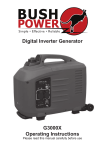
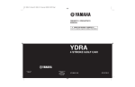
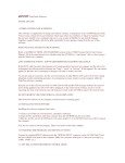
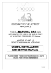
Digital Inverter Generator
G4000X
Operating Instructions
Please read this manual carefully before use
Thank you for purchasing our generator.
This manual covers operation and maintenance of the G4000X.
All information in this publication is based on the latest product information
available at the time of approval for printing. We reserve the right to make
changes at any time without notice and without incurring any obligation.
The copyright of this manual belongs to our company, no part of this
publication may be reproduced without written permission.
This manual should be considered a permanent part of the generator and
should remain with it if it is resold.
Pay special attention to statements preceded by the following words
WARNING
It indicates a strong possibility of severe personal injury or death if
instructions are not followed.
CAUTION
It indicates a strong possibility of severe personal injury or death if
instructions are not followed.
If a problem should arise, or if you have any questions about the
generator, consult an authorized dealer.
BE CAREFUL
The generators are designed to give safe and dependable service if
operated according to instructions. Read and understand the Owner’s
Manual before operating the generator. Failure to do so could result in
personal injury or equipment damage.
WARNING
•
The generator is designed to give safe and dependable service if
operated according to instructions. Read and understand this manual
carefully before operating the generator, or it may cause serious injury
and equipment damage.
WARNING
•
Exhaust contains poisonous carbon monoxide. Do not operate
generator in confined environment or with an aerator. Only use
outdoors and far from open windows doors and vents.
WARNING
•
•
The muffler becomes very hot during operating and remains hot for
a while after stopping the engine. Be careful not to touch the muffler
while it is hot. Let the engine cool before storing the generator indoors.
The engine exhaust system will be heated during operation and
remain hot immediately after stopping the engine. To prevent scalding,
pay attention to the warning marks attached to the generator.
WARNING
•
Do not parallel connect other cables to receptacles. You must use the
special jack, or it may cause an electrical shock.
WARNING
•
•
•
•
Gasoline is extremely flammable and is explosive under certain
conditions.
Refuel in a ventilated area with engine stopped.
Keep away from cigarettes, smoke and sparks when refuelling the
generator.
Always refuel in a well-ventilated location.
WARNING
•
Connection for standby power to a building electrical system must
be made by a qualified electrician. The connection must isolate the
generator from utility power, and must comply with all applicable laws
and electrical codes. Improper connections to a building electrical
system can allow electrical current from the generator to backfeed
into the utility lines. Such backfeed may electrocute utility company
workers or others who contact lines during a power outage, and the
generator may explode, or cause fires when utility power is restored.
WARNING
•
•
•
•
•
•
•
•
•
To avoid accidents and equipment damage, check generation system
every time before starting engine.
Keep the generator a distance at least 1 meter from other equipment
during operation.
Keep the generator upright when running. If generator is tilted, it may
cause fuel spillage.
Generator operators must be trained, must know how to stop the
generator quickly and understand the operation of all controllable
parts. Untrained operators should not be allowed to use this
equipment.
Keep children and pets away from operating area.
Keep away from rotating parts during operation.
The generator is a potential source of electrical shock when misused.
Do not operate it with wet hands or in any wet location.
Do not operate the generator in rain or snow, or let it get wet.
WARNING
Read this manual carefully before using the machine, for your own safety.
You should only use the generator according to these instructions.
COMPONENT IDENTIFICATION
1. Fuel cap
2. Air vent knob
3. Choke knob
4. Control panel
5. Starting grip
6. Fuel valve grip
7. Maintenance cover
8. AC socket
9. Overload indicator light
10. Output indicator light
11. Oil alert indicator light
12. Eco throttle switch
13. Engine switch
14. DC socket
15. DC circuit breaker
16. Grounding terminal
CONTROL PANEL
SMART THROTTLE
Engine speed is kept at idle automatically when the electrical appliance
is disconnected and it returns to the required speed to power the
electrical load when the electrical appliance is connected. This position is
recommended to minimize the fuel consumption while in operation.
SAFETY INSTRUCTIONS
•
•
•
•
•
•
•
•
•
•
•
•
•
•
•
•
•
•
The generator is designed to give safe and dependable service if
operated according to instructions..
Read and understand the Owner’s Manual before operating the
generator. Failure to do so could result in personal injury or equipment
damage.
Exhaust gas contains poisonous carton monoxide. Never run the
generator in an enclosed area. Be sure to provide adequate ventilation.
The muffler becomes very hot during operation and remains hot for a
while after stopping the engine. Be careful not to touch the muffler white
it is hot. Let the engine cool before storing the generator indoors.
The engine exhaust system will be heated during operation and remain
hot immediately after stopping the engine. To prevent scalding, pay
attention to the warning marks.
Gasoline is extremely flammable and explosive under certain conditions.
Refuel in a well ventilated area with the engine stopped.
Keep away from cigarettes, smoke and sparks when re-fuelling the
generator. Always refuel in a well ventilated location.
Clean up spilled gasoline at once.
Connections for standby power to a building’s electrical system must be
made by a qualified electrician and must comply with all applicable laws
and electrical codes. Improper connections can allow electrical current
from the generator to back feed into the utility lines.
Such back feed may electrocute utility company workers or others
who contact the lines during a power outage, and when utility power
is restored, the generator may explode, burn, or cause fires in the
building’s electrical system.
Always make a pre-operation inspection before you start the engine. You
may prevent an accident or equipment damage.
Place the generator at least 1m (3ft) away from buildings or other
equipment during operation.
Operate the generator on a level surface. If the generator is tilted, fuel
spillage may result.
Know how to stop the generator quickly and understand the operation
of all the controls. Never permit anyone to operate the generator without
proper instructions.
Keep children and pets away from the generator when it is in operation.
Keep away from rotating parts while the generator is running.
The generator is a potential source of electrical shocks when misused;
do not operate with wet hands.
Do not operate the generator in rain or snow and do not let it get wet.
SAFETY LABEL LOCATIONS
These labels warn you of potential hazards that can cause serious injury.
Read the labels, safety notes and precautions described in the manual
carefully.
If a label comes off or becomes hard to read, contact your dealer for a
replacement.
PRE-OPERATION CHECK
Be sure to check the generator on a level surface with the engine stopped
and the brakes are tightened.
Make sure no other equipment, objects, buildings or hazards are within 1
metre of the generator. Apply the brakes on the wheels before starting the
generator.
Check the engine oil level
Using non-detergent oil or 2-stroke engine oil could shorten the engine’s
service life.
Use high-detergent, premium quality 4 –stroke engine oil, certified to meet
or exceed U.S. automobile manufacturer’s requirements for API Service
Classification SG .SF.(15W40)
Select the appropriate viscosity for the average temperature in your area.
SAE Viscosity Grades
Loosen the cover screw and remove the left side maintenance cover.
Remove the oil filler cap, and wipe the dipstick with a clean rag. Check the
oil level by inserting the dipstick in the filler hole without screwing it in.
If the oil level is below the end of the dipstick, refill the recommended oil
up to the top of the oil filler neck.
The Oil Alert System will automatically stop the engine before the oil
level falls below the safe limit. However, to avoid the inconvenience of an
unexpected shutdown, it is still advisable to visually inspect the oil level
regularly.
Check the fuel level
Turn the fuel cap lever to “OFF” position before transporting.
Use automotive fuel (Unleaded or low leaded is preferred to minimize
combustion chamber deposits).
!! Don’t use fuel containing ethanol or alcohol: Fuel system damage or
engine performance problems resulting from the use of fuels that contain
ethanol or alcohol are not covered under the warranty.
Never use an oil/gasoline mixture or dirty gasoline.
Avoid getting dirt, dust or water in the fuel tank.
After refuelling, tighten the fuel filler cap securely.
Gasoline is extremely flammable and is explosive under certain conditions.
Refuel in a well-ventilated area with the engine stopped.
Do not smoke or allow flames or sparks in the area where the engine is
refuelled or where gasoline is stored.
Do not overfill the fuel tank. After refuelling, make sure the tank cap is
closed properly and securely.
Be careful not to spill fuel when refuelling. Spilled fuel or fuel vapour may
ignite. If any fuel is spilled, make sure the area is dry before starting the
engine.
Avoid repeated or prolonged contact with skin or breathing of vapour.
KEEP OUT OF REACH OF CHILDREN
Check the air cleaner
Check the air cleaner element to be sure it is clean and in good condition.
1. Loosen the cover screw and remove the left side maintenance cover.
2. Press the latch tab on the top of the air cleaner body, remove the air
cleaner cartridge, and check the element.
3. Clean or replace the element if necessary.
Never run the engine without the air cleaner. Rapid engine wear will
result from contaminants, such as dust and dirt, being drawn through the
carburettor, into the engine.
It is normal for a little oil to appear under the air filter box if the generator
is running for a long period of time, or a lot of oil is in the engine. Wipe up
excess oil after each use and after stopping the generator.
GENERATOR USE
Starting the engine
Before starting the engine, disconnect any load from the DC receptacle.
The first time starting the engine, or restarting the engine after a long time
by electric starter, if the engine can’t be started, please use the recoil
starter to start the engine
1. Turn the fuel cap lever fully clockwise to the ON position.
2. Put the electric start key into engine switch, and turn it to “ON” position
3. Turn the electric start key to “START” position until the engine has
started.
Starting the engine (Recoil Starter)
1. Turn the fuel cap lever fully clockwise to the ON position.
2. Put the electric start key into engine switch, and turn it to “ON” position
3. Pull the starting grip lightly until resistance is felt, then pull briskly to
start the engine.
High Altitude Operation
At high altitude, the standard carburettor air –fuel mixture will be
excessively rich.
Performance will decrease, and fuel consumption will increase.
High altitude performance can be improved by installing a smaller
diameter main fuel jet in the carburettor and readjusting the slow tempo
screws. If you always operate the generator at altitudes higher than
1,500m (4,000 feet) above sea level, have your dealer perform these
carburettor modifications.
Even with suitable carburettor jetting, engine horsepower will decrease
approximately 3.5% for each 300m (1,000 feet) increase in altitude .
The effect of altitude on the horsepower will be greater than this if no
carburettor modification is made.
Operation of the generator at an altitude lower than the carburettor
is jetted for may result in reduced performance, overheating , and
serious engine damage caused by an excessively lean air/fuel
mixture.
Generator Use
Warning
•
•
•
•
•
•
To prevent electrical shock from faulty appliances , the generator
should be grounded. Connect an electric conductor (cable) of at least
1.5mm2 between the generator’s ground terminal and an external
ground source.
Connections for standby power to a building’s electrical system must
be made by a qualified electrician and must comply with all applicable
laws and electrical codes. Improper connections can allow electrical
current from the generator to back feed into the utility lines. Such
back feed may electrocute utility power is restored ,the generator may
explode, burn, or cause fires in the building’s electrical system.
Do not exceed the current limit specified for any one receptacle
Do not connect the generator to a household circuit . This could cause
damage to the generator or to electrical appliances in the house.
Do not modify or use the generator for any other purpose than it is
intended for. Also observe the following when using the generator.
—Do not connect generators in parallel.
—Do not connect an extension to exhaust pipe.
When an extension cable is required , be sure to use a rubber
sheathed flexible cable,
•
•
•
•
Limit length of extension cables 60m for cables of 1.5mm2 and 100m
for cables of 2.5mm2.
Keep the generator away from other electric cables or wires such as
distribution network.
The DC receptacle can be used while the AC power is in use. If you
use both at the same time, be sure not to exceed the total power for
AC and DC.
Most appliance motors require more than their rated wattage for startup.
AC applications
1. Start the engine and make sure the output indicator light (green)
illuminates.
2. Confirm that the appliance to be used is switched off, and plug in the
appliance.
•
•
Substantial overloading that continuously lights the overload indicator
light (red) may damage the generator. Marginal overloading that
temporarily lights the overload indicator light (red) may shorten the
service life of the generator.
Be sure that all appliances are in good working order before
connecting them to the generator, if an appliance begins to operate
abnormally, becomes sluggish, or stops suddenly, turn off the
generator immediately. Then disconnect the appliance, and examine it
for signs of malfunction.
Output and Overload Indicators
The output indicator light (green) will remain lighted during normal
operating conditions.
If the generator is overloaded or if there is a short in the connected
appliance, the output indicator light (green) will go OFF, the overload
indicator light (red) will go ON and current to the connected appliance will
be shut off.
Stop the engine if the overload indicator light (red) switches ON and
investigate the overload source.
Before connecting an appliance to the generator, check that it is in
good order, and that its electrical rating does not exceed that of the
generator. Then connect the power cord of the appliance and start
the engine.
Be sure all equipment is turned off before plugging in the power
cord.
When an electric motor is started, both the overload indicator light (red)
and the output indicator light (green) may go on simultaneously. This
is normal if the overload indicator light (red) goes off after about four
seconds.
If the overload indicator light (red) stays on, consult your dealer.
1. Connect the ground terminal
2. Start engine according to “STARTING THE ENGINE”
When the output indicator light (green) does not light and the
overload indicator light (red) lights instead, set the engine switch to
STOP, stop the engine at once and then start the engine again.
3. Confirm that the equipment to be used is switched off, and insert the
plug of the equipment to be used into the AC receptacle unit A.
Check that the equipment to be connected is switched off. When
the equipment to be used is switched on, it can start suddenly, and
injuries or accidents may be caused.
4. Switch on the equipment and the output indicator light will light up. In
case of overload operation or when trouble occurs for the equipment
being used, the output indicator light (green) will go out, the overload
indicator light (red) will light continuously, and no power will be put
out. At this time the engine will not automatically stop, so it must be
stopped by setting the respective engine switch to STOP.
When equipment requires a large starting power, the overload
indicator lights (red) and the output indicator light (green) may light
together for a short time, but this is no abnormality. After starting the
equipment, the overload indicator light (red) will go out after a few
seconds and the output indicator light (green) will stay lit.
Connected Load
2000W Incandescent lamps
2000W Power Tools / Fluorescents
1000W Fridge / Compressors
Suggested
DC Battery
Generator Size
2000W
Rated
voltage 12v
2500W
4000W
Note: This table is a guide only. In some instances such as large air conditioners,
etc, a generator up to six times the load may be required.
DC Applications
For charging 12V automotive batteries:
Opening the smart throttle
Closing the smart throttle
DC Max. output power
Ldling
voltage (V)
22
27
37
Loading
voltage (V)
12
13
13.5
Loading
current (A)
6
8.5
8.5
The generator cannot sense a variable load with the same power which
the manual indicates. It only can sense 40%-70% power which the manual
indicates.
Example:
Model
G4000X
Generator rated output
Frequency
Power factor
AC
1.0
0.8
DC
3.7KVA
0-3.7KVA
4.6KVA
12V/8.3A
•
•
•
•
•
•
•
•
•
•
•
When using the DC output, turn Smart Throttle to the OFF position.
The DC current will be below 5A if turning on the Smart Throttle
without AC current output.
When charging batteries, person must be present to monitor the
voltage. Stop charging when the voltage of the batteries is above 16V.
Or it may cause battery explosion, resulting in serious injury or death.
To prevent the possibility of creating a spark near the battery, connect
charging cable first to the generator, then to the battery. Disconnect
cable first at the battery.
Before connecting charging cables to a battery that is installed in a
vehicle, disconnect the vehicles grounded battery cable. Reconnect
the vehicle’s grounded battery cable after the charging cables are
removed. This procedure will prevent the possibility of short circuit and
sparks if you make accidental contact between a battery terminal and
the vehicle’s frame or body.
Do not attempt to start an automobile engine while the generator is still
connected to the battery, the generator may be damaged.
Connect the positive battery terminal to the positive charging cord. Do
not reverse the polarity of the charging cables, or serious damage to
the generator and/or the battery may occur.
The battery can give off explosive gases; keep spark, flames and
cigarettes away. Provide adequate ventilation when charging.
The battery contains sulphuric acid (electrolyte). Contact with skin or
eyes may cause severe burns. Wear protective clothing and a face
shield.
If electrolyte gets on your skin, flush with water.
If electrolyte gets in your eyes, flush with water for at least 15 minutes
and call a physician.
Electrolyte is poisonous.
•
•
If swallowed, drink large quantities of water or milk and follow with milk
or magnesia or vegetable oil and call a physician.
KEEP OUT OF THE REACH OF CHILDREN, PETS AND UNTRAINED
PEOPLE.
Start the engine
•
•
The DC receptacle may be used while the AC power is in use.
An overloaded DC circuit will trip the DC circuit breaker. If this
happens, disconnect the DC load before pushing in the circuit breaker
to resume operation.
Oil alert system
•
•
The oil alert system is designed to prevent engine damage caused
by an insufficient amount of oil in the engine. The alert system will
automatically shut down the engine if a low oil level is detected (the
engine switch will remain in the ON position).
If the oil alert system shuts down the engine, the oil alert indicator light
(red) will come on when you operate the starter and the engine will not
run. If this occurs, add engine oil.
Stopping the engine
To stop the engine in an emergency, turn the engine switch to the OFF
position.
In normal use:
1. Switch off the connected equipment and pull the inserted plug out.
2. Turn the engine switch to the OFF position.
3. Turn the cap level fully counter clockwise to the “OFF” position.
Be sure to tighten the fuel cap and the engine switch are in “OFF”
position when stopping, transporting and/or storing the generator.
Maintenance
•
•
The purpose of the maintenance and adjustment schedule is to keep
the generator in the best operating condition.
Inspect or service as scheduled in the table below
Shut off the engine before performing any maintenance. If the engine
must be run, make sure the area is well ventilated, the exhaust
contains poisonous carbon monoxide gas.
Use authorized parts or their equivalent. The use of replacement
parts which are not of equivalent quality may damage the generator.
Maintenance Schedule
Note
1. Log hours of operation to determine proper maintenance.
2. Service more frequently when used in dusty areas.
3. These items should be serviced by an authorized dealer, unless the
owner has the proper tools and is mechanically proficient. See the
Shop Manual.
Temperature (℃)
25
30
35
40
Time for changing oil
(hour)
Normal
18
15
12
Recommended power
factor
100%
95%
85%
70%
Changing oil
Drain the oil while the engine is still warm to assure rapid and complete
draining.
Make sure to turn the engine switch and the fuel cap vent lever OFF
before draining.
1. Lean the generator.
2. Fasten the oil lead pipe on the oil exhaust as the picture. Then pour
out the oil.
3. Refill the new oil and check the oil position in the crankcase.
4. After refill the new oil into the crankcase , please shake the generator
left to right a few times and make sure the bobber of the oil alarm
system is floating.
5. Reinstall the side maintenance cover and tighten the cover screw
securely.
Engine oil capacity :1.0L
Refill oil
1.
2.
3.
4.
Remove the screws and open the access panel.
Revolve out the dipstick.
Revolve the oil filling pipe into the oil filter hole.
Use the oil filling bottle to pour the oil into the crankcase and check the
oil level
After refilling the new oil into the crank case, please shake the generator
left to right a few times and make sure the bobber of the oil alarm system
is floating.
Wash your hands with soap and water after handling used oil.
Please dispose of used motor oil in a manner that is considerate of
the environment. We suggest you take it in a sealed container to your
local service station for disposal. Do not throw it in the trash or pour
it on the ground.
Air Cleaner Service
A dirty air cleaner will restrict air flow to the carburettor. To prevent
carburettor malfunction, service the air cleaner regularly. Service more
frequently when operating the generator in extremely dirty areas.
Do not use gasoline or low flash point solvents for cleaning. They
are flammable and explosive under certain conditions.
1. Loosen the cover screw and remove the access panel.
2. Remove the screw under the air filter case.
3. Pull the air filter cartridge down 30mm and remove the air filter
cartridge.
4. Remove the air filter iron clip and check the air filter element. Clean or
replace the element if necessary.
5. Reinstall the air filter parts after cleaning or replacing air filter element.
Spark Plug Servicing
Please use high quality authentic spark plugs.
To ensure proper engine operation, the spark plug must be properly
gapped and free of deposits.
1. Remove the bolts on the top maintenance cover and the cover.
2. Take out the ignition coil rubber boot.
3. Remove the spark plug with the spark plug wrench.
4. Visually inspect the spark plug. Discard it if the insulator is cracked or
chipped. Clean spark plug with a wire brush if it is to be reused.
5. Install the spark plug carefully by hand, to avoid cross-threading.
6. After a new spark plug has been seated by hand, it should be
tightened 1/2 turn with a wrench to compress its washer. If a used plug
is being reinstalled, it should only require 1/8 to 1/4 turns after being
seated.
7. Reinstall the ignition coil rubber boot on the spark plug securely.
8. Reinstall the controlling panel.
The spark plug must be securely tightened. An improperly tightened
plug can become very hot and possibly damage the generator.
Never use a spark plug with an improper heat range.
Never use a spark plug without damping resistance, or it will cause
no AC output.
Transporting and Storage
To prevent fuel spillage when transporting or during temporary storage,
the generator should be secured upright in its normal operating position,
with the engine switch OFF.
The fuel cap vent lever is turned counter clockwise to the OFF position.
Allow the engine to cool well before turning the fuel cap vent lever to the
OFF position,
When transporting generator:
•
•
•
•
Do not overfill the tank (there should be no fuel in the filler neck).
Do not operate generator while it is in a vehicle. Take the generator out
of the vehicle and use it in a well-ventilated place.
Avoid a place exposed to direct sunlight when putting the generator
on a vehicle. If the generator is left in an enclosed vehicle for many
hours, high temperature inside the vehicle could cause fuel to vaporize
resulting in a possible explosion.
Do not drive on a rough road for an extended period with the generator
on board. If you must transport the generator on a rough road, drain
the fuel from the generator beforehand.
Before storing the unit for an extended period:
1. Be sure the storage area is free of excessive humidity and dust.
2. Drain the fuel.
Gasoline is extremely flammable and explosive under certain
conditions.
Do not smoke or allow flames or sparks in the area.
3. Completely drain the fuel from the tank. Open the fuel valve, start the
engine and operate it in the idle position until all remaining fuel is gone
and the engine stops automatically.
4. Discharge oil.
5. Remove spark plug and fill cylinder with 2cc’s fresh oil. Pull start cord
3-4 times to discharge the remaining oil. Then reinstall the spark plug. 6. Pull the staring cord slowly until resistance is strong . At this time, the
piston is moving to the top of the compression stroke and the valves
will be closed.
Fire net muffler service
A dirty muffler will increase noise and affect the engine’s running.
Clean and maintain the fire net regularly, to make sure the generator
works normally.
The fire net of the muffler needs cleaning frequently if you use the
generator in very dirty conditions and replace the fire net if necessary.
•
•
1.
2.
3.
4.
Before clean the fire net of muffler make sure the generator is not
running.
Before check and maintenance the fire net of the muffler, make sure
the generator is cool or risk being burned by the hot muffler.
Remove the M6 screws and open the muffler cover.
Remove two M4 screws on the fire net.
Take down the fire net as per the following figure.
Check the fire net, clean or replace it if necessary.
TROUBLESHOOTING
•
•
•
Shake the generator several times from side to side to make the oil
float rise, if the generator cannot start after adding oil for the first time
and the oil alarm indicator stays on when pulling the starting cord.
Make sure there is no spilled fuel around the spark plug. Spilled fuel
may ignite.
If the engine still doesn’t start, have the generator repaired by a
licensed repair person.
INSPECTION:
1. Remove the spark plug rubber boot and clean any dirt from around the
spark plug
2. Remove the spark plug and place it in the spark plug rubber boot.
3. Connect the side electrode of the spark plug to the metal parts of the
engine.
4. Pull the starting cord. A spark could jump across the gap.
The equipment that connects generator doesn’t start
There is no power in the direct current electric outlet
There is no power in the DC electric outlet
Deficient AC output
Specifications
Item
L x W x H(mm)
Net weight(kg)
G4000X
600 x 450 x 500
50
Engine Specifications
Item
Model
Type
Displacement
Compression ratio
Engine speed
Cooling system
Ignition system
Oil capacity
Fuel tank capacity
Spark plug
Noise level(4m)
Continuous Operation
G4000X
176F/185F
4-stroke, OHV, 1-cylinder
269CC/357CC
9.2:1
2200 - 3600 RPM
Forced air cooling
TDI
1.0
14L
NGK
59dB
5.5h
Generator Specifications
Type
Item
AC output
Rated voltage (V)
Rated frequency(HZ)
Rated current(A)
Rated output(KVA)
Maximum output(KVA)
Rated voltage(V)
Rated current(A)
DC output (For 12V
automotive batteries
only)
Part Number
G4000X
110/120/220/230/240
50/60
27/25/13/12.5
3.7
[email protected]Øcos
12
8.3
Wiring Diagram
Exploded Parts View
Bush Power - Warranty Against Defects Procedure
Bush Power
A subsidiary of The Matson Group Pty Ltd
100 Links Rd, St Marys, NSW 2760
Phone: 02 98333444
Email: [email protected]
www.matson.com.au
Warranty
Bush Power warrants its products to be free of defects for reasonable
consumer use for a period of 12 months. Bush Power will repair or
replace the warranted product and it will return the repaired products
under warranty to the consumer at Bush Power’s cost.
To make a claim under this warranty, the consumer must:
•
advise Bush Power of the defect as soon as it becomes apparent
within 12 months of the purchase date and obtain a return authority by
phoning Bush Power on the above number.
•
provide satisfactory proof of purchase; and
•
send the faulty item to the address supplied above.
Exclusions from Warranty
This warranty does not apply to products where:
•
there is evidence of Improper maintenance or abuse to the products;
•
the products have been exposed to harsh environmental conditions or
those outside the specified operating conditions;
•
Unauthorised modification is evident to the products or misuse of
products;
•
Operation outside the products specification.
Warranty Disclaimers
Bush Power’s liability in respect of a breach of a consumer guarantee
or any warranty made under these warranty terms and conditions for
any products not of a kind ordinarily acquired for personal, domestic or
household use is limited, in relation to the products to the extent
permissible by law and at it’s option to:
•
replacing the products or the supply of equivalent goods;
•
the repair of the products;
•
the payment of the cost of replacing the products or of acquiring
equivalent goods; or
•
the payment of the cost of having the products repaired.
To the extent permitted by law, all other warranties whether implied or
otherwise, not set out in these warranty terms and conditions are excluded
and we are not liable in contract, tort (including, without limitation,
negligence or breach of statutory duty) or otherwise to compensate the
customer for:
•
any increased costs or expenses;
•
any loss of profit, revenue, business, contracts or anticipated savings;
•
any loss or expense resulting from a claim by a third party; or
•
any special, indirect or consequential loss or damage of any nature
whatsoever caused by Bush Power’s failure in complying with its
obligations.
BUSH POWER IS NOT RESPONSIBLE FOR DAMAGE THAT OCCURS
AS A RESULT OF YOUR FAILURE TO FOLLOW THE INSTRUCTIONS
INTENDED FOR THE BUSH POWER PRODUCT
In the following paragraph, “Our” means Bush Power and “You” means the
customer:
Our goods come with guarantees that cannot be excluded under the
Australian Consumer Law. You are entitled to a replacement or refund for
a major failure and for compensation for any other reasonably foreseeable
loss or damage. You are also entitled to have the goods repaired or
replaced if the goods fail to be of acceptable quality and the failure does
not amount to a major failure.
The benefits given to the customer in this warranty are in addition to other
rights and remedies under a law in relation to the products to which this
warranty applies.
Warranty Card
(To be detatched and returned with the unit to the below address)
Name:
Company Name:
Address:
Ph:
Fax:
E-mail:
Purchased From:
Date Purchased:
Product Purchased (Model No.):
This product is supplied with a 5 Year Warranty from date
of purchase.
Please Note:
• Should you experience any warranty related issues with
this charger please call Matson Warranty Department on
(02) 9833 3444 between the hours of 8am - 4:00pm
Monday - Friday.
• Our Warranty Department will issue instructions so please
contact them before returning the charger.
• Proof of Purchase will be required for all warranty claims.
The Matson Group Pty Ltd
100 Links Road
St Marys NSW 2760 Australia
Ph: (02) 9833 3444 Fax: (02) 9833 3500
[email protected]
www.matson.com.au