1
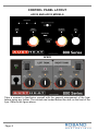
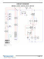
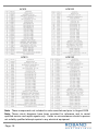
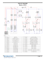
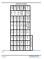
. Manufactured By ROBAND AUSTRALIA PTY LTD OPERATING INSTRUCTIONS FREE STANDING FRYERS Models: AF812, AF812R, AF813, AF813R Version 2 AF822 Version 1 Special Features: Swing Up Ultra-Durable Stainless Steel Elements Easy Clean Tank with Lockable 1” Drain Adjustable Legs & Rear Castors Digital LED Temperature Display Fish Plate & Fish Plate Lifter Stainless Steel Baskets Cook/Idle Selector Switch These instructions cover the models of High Performance Free Standing Deep Fryers listed above. Although there are slight variances between models, the installation, operation, care and maintenance procedure is the same for all. 8/09/2014 Roband® Australia is a wholly Australian owned company and has been manufacturing quality commercial catering equipment for the food service industry for more than 50 years. Roband products are engineered and manufactured to the highest standards to provide functionality, reliability and durability, and our quality products are exported world-wide. Included in the comprehensive Roband® range are Toasters, Fryers, Milkshake Mixers, Rotisseries, Food Display Cabinets and much more. Roband® Australia also acts as the Australian agents for Vitamix® Blenders, Noaw® Meat Slicers, Förje® Cookware, RobalecTM Soup/Rice Warmers, Robatherm Urns, Austheat® Fryers, Dipo Induction & Autofry Machines. Roband also has its own line of commercial cookware and cutlery under the Robinox® brand name. For a complete set of brochures please contact your nearest authorised dealer or contact Roband directly at our head office. Roband Head Office Sydney, Australia Roband Australia Pty Ltd 1 Inman Road Dee Why NSW 2099 AUSTRALIA Tel: +61 2 9971 1788 Fax: +61 2 9971 1336 Email: [email protected] Web: www.roband.com.au International Agents For additional agents please email Head Office Cyprus: Fiji: Hong Kong: Malaysia: Maldives: New Zealand: Noumea: Papua New Guinea: Singapore: United Catering Equipment Supplies Ph: +357 777 777 24 Hotel Equipment Ltd Ph: +679 672 0666 Chung Wah Kitchen Machine Ltd Ph: +852 2334 5411 Allied Food Equipment Ph: +603 9133 5833 Radiant Heat Maldives Pty Ltd Ph: +960 333 4845 Roband New Zealand Ph: +649 274 1354 Comptoir Materiel Professionnel Ph: +687 28 50 43 Brian Bell & Company Pty Ltd Ph: +675 325 5411 Allied Foodservice Equipment Ph: +65 62525880 Switzerland: Thailand: United Arab Emirates: United Arab Emirates: United Kingdom: USA: USA: NETHERLANDS GREECE Burgi Infra Grill Ph: +41 418 554 552 Seven Five Distributors Co Ltd Ph: +662 866 5858 Boncafe Middle East LLC +9714 282 8742 Nisa Trading LLC +9714 396 6132 Metcalfe Catering Equipment Ph +44 1766 830 456 Condon & Fisher International Ph: +1 508 361 9226 Condon & Fisher International Ph: +1 508 361 9226 AKB Bert Muller Ph: +31 306 017 442 K&N Engineers Ltd Ph: +30 210 520 0440 © Copyright 2014 – Roband® Australia Pty Ltd All rights reserved. No part of this work may be reproduced or copied in any form or by any means, electronic or mechanical, including photocopying or posting to a website, without the written permission of the publisher. The material contained within this document is intended entirely for instructional purposes. CONTENTS INTRODUCTION ..................................................................................................... 1 GENERAL PRECAUTIONS ..................................................................................... 1 PACKAGING ........................................................................................................... 2 COMPLIANCE ......................................................................................................... 2 INSTALLATION ....................................................................................................... 3 GENERAL ARRANGEMENT ................................................................................... 4 CONTROL PANEL LAYOUT ................................................................................... 5 OPERATION.......................................................................................................... 10 TIPS FOR HEALTHY FRYING .............................................................................. 12 TIPS ON DEEP FRYING ....................................................................................... 13 GENERAL SAFETY ............................................................................................... 15 CLEANING, CARE & MAINTENANCE .................................................................. 16 TROUBLESHOOTING ........................................................................................... 17 CIRCUIT DIAGRAM............................................................................................... 18 SPECIFICATIONS ................................................................................................. 21 SPARE PARTS LIST ............................................................................................. 22 EC DECLARATION OF CONFORMITY ................................................................. 27 WARRANTY .......................................................................................................... 28 INTRODUCTION Congratulations on your purchase of this quality Austheat® product. With proper care and management your new purchase will give you years of trouble free service. By reading these instructions carefully you can ensure that this machine is used and maintained properly, helping your new investment to perform well for you now, and to continue performing in the many years to come. GENERAL PRECAUTIONS These fryers must only be operated by qualified person(s) who are fully versed in the operating and safety instructions described in this manual. Servicepersons should be instructed to familiarise themselves with any and all safety instructions described in this manual prior to commencement of any maintenance or service. In case of new personnel, training is to be provided in advance. These fryers should not be operated by children or infirm persons without adequate supervision. These fryers should NOT be left unattended during operation. These fryers are heating units, and, as with any commercial heating unit the surfaces on them will get hot. Always be careful when near an operating fryer, and ensure that any risk to unwary customers or staff is minimised with additional signage if necessary. Due to the obvious heat hazard, Austheat® recommends that these fryers be kept out of reach of children. These fryers are for use with oil only. The fryers are not designed for use with water or for such tasks as cooking pasta. Any use with water will void the warranty for the fryer. These fryers should be disconnected from all power via the main switch and allowed to cool before attempting to carry out any cleaning and maintenance routines. Austheat® will not accept liability if; Non-authorised personnel have tampered with the machine. The instructions in this manual have not been followed correctly. Non-original spare parts are used. The machine is not cleaned and maintained correctly. There is any damage to the unit caused by the operator. Page: 1 PACKAGING All care is taken when packing and Austheat® ensures that every unit is functional and undamaged at the time of packaging. The Package of these Fryers should include: AF812 1. 2. 3. 4. 5. 6. 7. 8. One AF Series Fryer (appropriate model) Tank Lid Fryer Baskets This Manual Strainer Fish Plates Fish Plate Lifter Packaging Materials 1 2 1 1 Quantity/Model AF813 1 1 3 1 1 1 1 1 AF822 2 2 2 2 Any damage to the machine as a result of freight must be reported to the Freight Company and to the agent responsible for the dispatch of the said unit within 24 hours of receipt. No claims will be accepted or entertained after this period. COMPLIANCE RCM: Austheat® products have been designed and manufactured to comply with any and all specifications set out by the Australian Communications and Media Authority (ACMA) in regards to Electromagnetic Compatibility. As testament to such compliance these units bear the RCM symbol. For further information contact the Australian Communications Authority, PO Box 13112, Law Courts, Melbourne VIC 8010. ACSS (ADVANCE CONTROL SAFETY SYSTEM): The ACSS framework is a stringent and specific set of voluntary requirements aimed at the electrical safety, reliability and longevity of equipment used in the foodservice industry. The ACSS framework has been developed as both a guide to the engineering and development of products as well as a guarantee to consumers that Austheat® equipment bearing this mark not only meets the requirements of the Australian Standards, they exceed them. A unit bearing the ACSS mark is your guarantee that you are purchasing a machine built to far exceed the Australian standards. The unit has been designed to be safer, particularly from an electrical aspect, and last longer than similar units on the market today. Page: 2 INSTALLATION BEFORE CONNECTION TO POWER SUPPLY Remove all the packaging materials and tape, as well as any protective plastic from the machine. Clean off any glue residue left over from the protective plastic using methylated spirit. Place the free standing fryer on a firm, level floor in the required position. The legs can be adjusted for slightly uneven floors. National Standards exist outlining the positioning, spacing and ventilation requirements when installing new appliances. These Standards should be consulted and new equipment should be installed accordingly. In any situation where specifications allow a distance of less than 100mm we would still recommend that a well-ventilated air gap of not less than 100mm be maintained. If the machine is near particularly heat-sensitive materials common sense should be employed in determining sufficient distancing. Consideration should be given to securing the unit or limiting mobility if the unit is hard-wired. Appropriate standards should be consulted when any installation is undertaken to ensure compliance with all requirements. ELECTRICAL CONNECTION Before connecting the fryer to the power supply ensure that all the controls are in the “OFF” position. A licensed electrician must install this fryer to comply with national installation codes and regulations. The fryers are supplied ready for connection to a three phase plus neutral and earth mains supply. Means for disconnection from supply must be incorporated in the fixed wiring in accordance with the wiring rules. WARNING - THIS UNIT MUST BE EARTHED. If the electrical mains supply cabling is damaged, the machine must not be used until a suitably qualified person has replaced the supply cabling and has deemed the unit to be functioning properly. There are two main supply connection points in the unit. The first is through the lower back panel at the rear of the unit. The second connection point is through the base of the machine at the rear. Both connection points have three choices of holes for the cable to pass through. A suitable cable gland is required for the cable to pass through. Each fryer must be connected to an adequately protected power supply and an isolation switch mounted adjacent to, but not behind the fryer. This switch must be clearly marked and readily accessible in case of fire. Page: 3 ELECTRICAL REQUIREMENTS The following table shows the electrical requirements for your fryer. Model Total Power Amps/Phase Supply AF812 15 kW 20.8 A 400-415 V AC, 3 Phase + N + E AF812R 18 kW 25 A 400-415 V AC, 3 Phase + N + E AF813 18 kW 25 A 400-415 V AC, 3 Phase + N + E AF813R 22.5 kW 32 A 400-415 V AC, 3 Phase + N + E AF822 15 kW 20.8 A 400-415 V AC, 3 Phase + N + E GENERAL ARRANGEMENT These fryers are designed as floor mounted units. They have a central cooking tank with immersed electric elements. The controls are accessed via the front door, located below the front display panel. The elements are mounted in a box on top of the fryer at the rear. This element box is pivoted and can be swung up to gain access to the tank and to the elements. Cooking baskets can be hung on the rail on the front of the element box allowing them to drain, after cooking, prior to serving. To raise the element box firstly remove the fish plate from the tank, using the lifter located on the bracket inside the door. A handle is provided that swings out from underneath the element box. To lift the element box, grasp the handle on the left side and swing it out towards the front of the fryer through 90°. The handle can then be used to lift the element box to the raised position. When lifted to the raised position, a support latch on the right hand side of the element box springs out to support the element box, enabling the elements to be drained and cleaned. WARNING: Always ensure the fryer is OFF, and is allowed to cool before lifting the element out of the oil. To lower the element box, lift with the handle a small amount to enable the support latch to be pushed towards the right which will clear the box and enable it to be lowered into the cooking position. The fish plate can be returned to the tank. WARNING: Immersing a hot element in the oil could cause a fire. Access to the drain and the controls is gained by opening the front door. The unit can be moved by lifting from underneath the front, just above the door, and pulling it along on the rear castors. Page: 4 CONTROL PANEL LAYOUT AF812 AND AF813 MODELS AF822 Take a moment to familiarise yourself with the general arrangement of the fryer before going any further. The controls are located behind the door on the front of the fryer. Refer to the figure above. Page: 5 CONTROL PANEL DESCRIPTION The controls consist of the following; A main isolating switch, labelled “ON/OFF SWITCH”. 1 primary thermostat, labelled “PRIMARY THERMOSTAT”. 1 secondary thermostat labelled “SECONDARY THERMOSTAT”. 1 thermal cut-out labelled “THERMAL CUT-OUT RESET BUTTON”. 1 melt cycle switch labelled, “MELT SWITCH”. 1 digital temperature display. Please note that this item is not visible on the control panel. It is mounted behind the display panel on the front of the fryer, above the door. 1 thermostat selector switch. This is mounted on the left side of the fryer on the front display panel opposite the temperature display. A safety cut-out switch which prevents the fryer from working when the elements are in the raised position. Please note that this switch is not visible on the control panel. It is mounted inside the element box. Various pilot lights indicating states of operation. These will be described in detail on page 9. Note: These controls, with exception for the main isolating switch, are duplicated for the AF822 model. The AF822 has two separate tanks with independent controls for each tank. CONTROLS LOCATED ELSEWHERE There are two complimentary controls located away from the control panel. These are: COOK/IDLE Switch for selecting either the primary or secondary thermostats. This chrome rotary switch (shown below) is located on the front of the machine. More details regarding the operation of the COOK/IDLE switch are given below. 1 Auxiliary thermal cut-out located at the rear of the machine. THERMOSTATS These fryers have 2 thermostats, 1 primary and 1 secondary. Only one thermostat is in use at a time. The thermostat selector switch (shown to the right) is used to select which thermostat is used to control the fryer. COOK/IDLE The secondary thermostat is designed to be used to place the fryer in an “IDLE” state such as when extended periods of no frying are experienced. By selecting the secondary thermostat, the oil temperature can be lowered to a desirable level, Page: 6 saving power. The recovery time to heat the oil to cooking temperatures is then reduced from that required to heat the oil from room temperature. The IDLE thermostat can also act as a redundant thermostat if the primary thermostat fails. If this occurs, set the thermostat selector switch to the IDLE position to continue cooking with the secondary thermostat. In the IDLE position, only the secondary thermostat is controlling the oil temperature. By adjusting the setting of the secondary thermostat to the desired cooking temperature, you can continue operation. This will allow the fryer to continue functioning until the primary thermostat is repaired. After the repair has been made the switch can be returned to the “COOK” position enabling the primary thermostat. THERMAL CUT-OUT These fryers have TWO thermal cut-out controls (or in the case of the AF822, FOUR cut-outs). These controls are designed to function in the following scenarios: The oil temperature reaches a dangerous level. The oil volume drops below the low level marker. Cooking elements are not sufficiently submerged in oil/ exposed to air. If either of these conditions is met, one or both thermal cut-outs will trip, cutting power to the elements. The thermal cut-outs can be manually reset. One thermal cut-out is located at the rear of the machine, on the back of the element box. If the oil temperature reaches a dangerous level, this cut-out will most likely trip first. The second thermal cut-out is located on the control panel which is access by opening the front door of the fryer. Front thermal cut-out Rear thermal cut-out When the thermal cut-out has tripped, a red button on the device will protrude out from the panel where it is located. This protrusion is an indication that the cut-out has tripped. If the thermal cut-out has tripped, it indicates that there is an underlying problem that has caused the oil to reach a dangerous temperature. Note: It is important to understand that old, dirty or low level oil can contribute to nuisance tripping of the thermal cut-outs. Always ensure that your oil is maintained and replaced when necessary. Refer to pages 12 to 14 for more details. Page: 7 What to do if the thermal cut-out trips for the first time: There are a number of possible causes of this behaviour. One of the possibilities is a thermostat failure. You may follow the procedure below as a first step to rectifying the problem. 1. Switch the fryer OFF and allow it to cool to approximately 100°C. 2. Visually determine which of the two thermal cut-outs has tripped. 3. Reset the thermal cut-out by pressing the red reset button. The control is reset when the button remains depressed. An audible click will also be heard. 4. Re-set the thermostat to the normal operating temperature and observe the unit closely. If the unit trips the thermal cut-out switch again, continue to step 5. If no cut-out occurs within an hour, continue to use the machine and monitor the temperature of the oil. 5. If the unit has activated the thermal cut-out switch twice in a short time, set the thermostat selector switch to the SECONDARY/IDLE position. This procedure assumes you were using the primary thermostat. If you were using the secondary thermostat when the fault occurred, then select the PRIMARY/COOK position in this procedure. 6. Cooking can now resume. If the fryer continues to perform without any further tripping of the thermal cut-out, then there is a strong possibility that the thermostat that was use at the time is faulty. This should be attended to by qualified electrical personnel. What to do if the thermal cut-out trips a second time: If the thermal cut-out trips again after following the above procedure, it indicates that there is a serious electrical problem that needs to be addressed immediately. In such cases follow the procedure below. 1. Turn OFF the fryer immediately. There may be a danger of fire. 2. DO NOT reset the thermal cut-out. 3. Seek advice from qualified electrical personnel. They will be able to check the fryer for faults and make any necessary repairs. Resume operation of the fryer only after it has been cleared for use by the electrical personnel charged with the repair. Page: 8 PILOT LIGHTS The control panel has a number of pilot lights. These pilot lights indicate the status of the fryer and are described below. The green pilot light above the main isolating switch illuminates when the fryer is switched on. This indicates that mains power is being supplied to the fryer. The amber pilot light beside the melt switch is illuminated when the melt cycle is being used. The amber pilot light above each thermostat is illuminated when the respective thermostat switches on and heating is taking place. When the thermostat cycles off after reaching the set temperature the pilot light will be extinguished. The pilot light’s labelled circuit breakers illuminate when there is power passing through the circuit breakers. If one of these lights isn’t illuminated, a circuit breaker has tripped and needs to be reset. If the circuit breakers continue to trip, seek advice from authorised service person or contact Roband Australia. TEMPERATURE DISPLAY The temperature displays can be seen on the display panel, located on the front of the fryer above the door. It displays the current temperature of the oil in each tank. Page: 9 OPERATION OIL LEVEL A raised form on the inner left hand side of the left tank indicates the oil level range. The upper and lower extremities of the raised form indicate the upper and lower oil level limits. The fryer should be filled with oil to a level which lies within the length of the form. Please note the following. The danger of fire exists if the oil level is below the minimum indicated level. The danger of surge boiling exists if the oil is above the maximum indicated level. The danger of surge boiling also exists if over-wet or too large a load is used Refer to the specifications page for the volume of oil required for your particular model. FILLING WITH LIQUID OIL Fill the tank with the required volume of oil using the following procedure. Ensure all controls are OFF, the drain valve is closed and the elements are cold. Place the strainer in position, lower the elements and place the fish plate in position. Fill the tank with the required volume of oil. The fryer is now ready for cooking. FILLING WITH SOLID OIL AND USING THE MELT CYCLE If solid oil or shortening is preferred this may be melted after filling by using the melt switch and the following procedure. Ensure all controls are OFF, the drain valve is closed and the elements are cold. Place the strainer in position and lower the elements. Do not place the fish plate into the tank at this time. Fill the tank with solid oil/shortening to sufficiently cover the elements. Switch the fryer ON at the main isolating switch. With the thermostat selector switch set to the PRIMARY position, set the primary thermostat to 120°. Switch the melt switch to ON. With this setting, the solid oil will be melted. A full tank will take approximately 40 minutes to melt but will vary according to the model you own. While melting, additional solid oil will need to be added to achieve the correct oil level. Care should Page: 10 be taken to ensure that the total volume of oil placed in the tanks is neither under or over the oil level marks as described above in “Oil Level”. During this phase, the fryer will remain protected by the control thermostat and the thermal cut-out. When melting is complete the melt switch should be returned to the OFF position and the fish plate lowered carefully into the tank. The fryer is now ready for cooking. COOKING 1. Fill the fryer tank with oil as described above. 2. Rotate the main switch to the “ON” position. illuminate, indicating that the power is on. The green pilot light will 3. Rotate the thermostat selector switches to the COOK position. 4. Rotate the primary thermostat knob to select the desired cooking temperature. For cooking, a setting of between 170° and 180°C should suffice but experience will dictate the best temperature for the particular food being cooked. When the temperature has been set the associated amber pilot light will illuminate, indicating that heating is taking place. When the oil has reached the set temperature the amber pilot light will be extinguished. The thermostat will then continue to cycle on and off, maintaining the set temperature. The amber pilot light will also cycle on and off with the thermostat. Once the fryer has reached the set temperature, it is ready for cooking to commence. The set temperature will be displayed on the temperature display panel. Note: the temperature displayed will fluctuate and will not display a static value equal to the set temperature of the thermostat. Lower the filled baskets into the oil carefully and do not over fill them. Refer to the specifications page to determine the maximum load you should work with. Shaking the baskets occasionally during cooking will help prevent the food from sticking together. Cooking time will vary with the type of food product being cooked and experience will guide you. With use, standard batch sizes, temperatures and cooking times can be established to enable consistent results. To obtain the optimum results from your fryer we recommend the following guidelines. Keep salt away from the cooking oil. Salt degrades the oil. Check your oil to food ratio, 6:1 oil to food is recommended. Top up the cooking oil regularly. Page: 11 TIPS FOR HEALTHY FRYING Are you concerned about your customers’ health? Would you like to improve the flavour and nutritional value of your fried product? And would you like to save money doing so? Then read on and take the first step towards a higher quality healthier product that can actually help save you money… VARIOUS TYPES OF FATS AND OILS Different types of oil or fat used to fry foods affect the overall nutritional quality of the finished product. Many of the various types of fats and oils available on the market are not suitable for cooking over long periods of time at high temperatures, as happens in deep-frying. Extra Virgin Olive Oil The flash point of Extra Virgin Olive Oil is considerably lower than the more refined Olive oils and should not be used for high temperature frying. Tallow-based (Beef) Fats The most commonly used fat due to its cheaper cost and relatively longer fry life. This medium is not recommended due to it’s association with increased risk of heart disease. Liquid Vegetable Oils While most vegetable oils are recommended for cooking, many of them are not suitable for deep-frying. Higher temperatures break down the oil faster and byproducts often have an unpleasant flavour and may also have an association with increased risk of heart disease. Hardened/Creamed Vegetable Oils These products may have a longer fry life than their liquid oil equivalents, but the components added during the hardening process increase the risk of heart disease. The Heart Foundation recommends frying oils that have a nutrient profile taking all these factors into account. These include: 1. Oils from specially bred seeds e.g. Sunola, Liquid Gold 2. Industry blends of fats and oils Page: 12 SAVING COSTS, IMPROVING OIL LIFE AND INCREASING EFFICIENCY Food quality and operating efficiency is improved by cooking in regularly filtered oil. Long oil life can be achieved by frequently filtering the oil inside the deep fryer. This allows the oil to work at greater efficiency for a longer time. This increased efficiency can be associated with power cost savings and a longer fry life for the oil. Several factors that shorten the fry life of the oil include the presence of water, salt, emulsifiers, seasoning, light and detergent. TIPS ON DEEP FRYING 1. USE THICK, STRAIGHT CUT CHIPS (GREATER THAN 13MM) OR WEDGES Thin chips and crinkle chips absorb more oil and therefore use up more oil from the fryer If the chips are frozen, don’t thaw. Water from thawed chips damages the oil 2. COOK AT 180°C Food won’t cook more quickly at temperatures above 180°C Higher temperatures damage the oil Damaged oil: -cooks more slowly. Uses more electricity to cook the food. Takes longer to get back up to temperature. Lower temperatures produce greasy food Turn fryer to 140°C during quiet times to save power and save the oil 3. COOK CHIPS IN A SEPARATE FRYER Fresh batter mix used for battered food, crumbs from crumb coatings, seasonings, sausages and seafood all damage the oil. If you have enough fryers, keep one fryer for chips only, this oil will last longer 4. COOK CHIPS FOR 3-4 MINUTES Page: 13 5. AVOID BIG DROPS IN OIL TEMPERATURE Big drops in temperature will damage the oil more quickly. Put small loads in the baskets If you have enough fryers, put baskets in alternate fryers. Keep fryers topped up with fresh oil. Don’t top up whilst cooking food. 6. DRAIN FOOD WELL Vigorously shake the basket of cooked food twice and hang it for at least 20 seconds over the hot fryer. This returns some oil to the fryer 7. LOOK FOR SIGNS OF OIL DEGRADATION If the oil is damaged (eg dark colour, smoking) discard it all. 8. FILTER OIL DAILY Use a funnel or a filtering machine The cost of a filtering machine will be offset by your savings on the oil Filtering extends the useful life of the oil Skim the surface of the oil frequently while cooking 9. CLEAN FRYER FREQUENTLY Detergent damages the oil. If you use detergent, rinse well after with a solution of white vinegar and water (1 cup of vinegar in a 20 litre bucket of water.) Finally rinse with water. 10. COVER THE FRYER WHEN NOT IN USE As light, dust and air damage oil, cover the fryer overnight and other times during the day when oil is cool. Page: 14 SAFETY GENERAL SAFETY This machine contains no user-serviceable parts. Austheat® Australia, one of our agents, or a similarly qualified person(s) should carry out all repairs. Any repair person(s) should be instructed to read the Safety warnings within this manual before commencing work on these units. Steel cutting processes such as those used in the construction of this machine result in sharp edges. Whilst any such edges are removed to the best of our ability it is always wise to take care when contacting any edge. Particular care should be taken to avoid contact with any steel edge, and warnings should be given in regards to the danger of such contact to any repair or maintenance person(s) prior to commencement of any servicing. Do not remove any cover panels that may be on the machine. This unit can get very hot, ensure everyone is aware that the machine is operating and take care to avoid contact with hot surfaces. (Refer to installation for guide to ventilation) Always ensure the power cable is not in contact with hot parts of the machine when in use, and ensure that if the cable is damaged in any way that it is replaced immediately SAFETY FEATURES All fryers in this range are equipped with a thermal cut-out, to protect against abnormal oil temperatures and a safety switch to prevent operation when the elements are in the raised position. Refer to the Control Panel Layout section previous for a functional description of these devices. GENERAL FIRE SAFETY Before using any fryer adequate safety measures should be in place. Such measures should include, but not be limited to, having an appropriate fire extinguisher or fire blanket located nearby in case cooking oil ignites. Refer to the appropriate regulations pertaining to your operating environment for details of the correct fire prevention measures required. Page: 15 COOKING SAFETY WARNING: Hot oil does not “look” hot. Do not be fooled into thinking that the oil is cool because of its placid appearance. WARNING: Ensure that oil is changed or filtered regularly. Old or dirty oil has a lower flash point and is more prone to surge boiling. WARNING: Always be careful when cooking frozen or over-wet food products as these items are more prone to surge-boiling and are more likely to result in the “spitting” of hot oil. WARNING: Do not overfill the cooking baskets beyond the guidelines. There is a danger of surge boiling when attempting to cook too much product. WARNING: Never use copper or brass utensils in the cooking oil. CLEANING, CARE & MAINTENANCE Attention to regular care and maintenance will ensure long and trouble free operation of your fryer. The fryer should be cleaned out daily, or more often if necessary. Ensure the power is off and the fryer is cool before attempting to drain the cooking oil or clean any part of the machine. Wipe the fryer down with warm soapy water using a damp sponge or cloth. Do not spray the fryer with a water jet from a hose or pressure cleaner. Filter the cooking oil daily if the fryer is constantly in use. Although every care is taken during manufacture to remove all sharp edges, care should be taken when cleaning to avoid injury. Caution: Some cleaning agents can damage stainless steel or the polycarbonates and plastics used in switches and pilot lights, usually through prolonged use. For this reason we recommend cleaning with soapy water only. Any damage to the unit through the use of harsh or improper cleaning agents is entirely the fault of the user. Warning: No parts of this these units, with the exceptions of the cooking baskets, lids, fish plates and strainers, should ever be immersed in water for cleaning or any other purposes. Note: We recommend that all electrical appliances be inspected annually with reference to applicable Australian Standards to ensure compliance with changing Standards is maintained. Such inspections should be carried out by a suitable person conversant with the latest Standard updates. Page: 16 TROUBLESHOOTING If the fryer does not function check the following points before calling for service. The power is switched “on”, both on the unit and at any other point that supplies power to the machine (eg an isolating switch on the wall). The mains power is not faulty. The temperature has been set correctly and the thermal cut-out has not tripped. Refer to the “Thermal Cut-Out” section previous for more information on this control. The thermostat knobs are not loose or broken, rendering the thermostats inoperable. The circuit breakers located inside the door behind the drains are all in the “on” position”. Page: 17 CIRCUIT DIAGRAM MODELS: AF812, AF812R, AF813, AF813R Page: 18 AF812 AF813 AF812R AF813R Note: These components not included in units manufactured prior to August 2008 Note: These circuit diagrams have been provided for reference and to assist qualified service and repair agents only. Under no circumstances should a person not suitably qualified attempt repairs to any electrical equipment. Page: 19 CIRCUIT DIAGRAM Models: AF822 Page: 20 SPECIFICATIONS Model AF812 AF812R AF813 Power Source 400 -415V AC 50/60 Hz 3 Phase + Neutral + Earth 15000 W Power Consump tion 1.25kg 1.25kg Recommended Batch Load per Basket 39 L 29 L 29 L Oil Volume 600mm 450mm 450mm Width 1080mm 1080mm 1080mm Height 800mm 800mm 800mm 800mm Depth Nominal Dimensions 18000 W 1.25kg 1080mm 18000 W 600mm 1.25kg 39 L 22500 W 800mm per tank 15L 1080mm 1.25kg 450mm 15000 W Page: 21 AF813R AF822 Constant research and development may necessitate specification changes at any time. SPARE PARTS LIST AF812(V2) Part No: EC0184 EC0206 EC0218 EC0245 EC0246 EC0247 EC0249 EC0256 EC0257 EC0258 EC0367 ES0206 ES0212 ES0231 HC0141 HC0149 MC0067 MC0074 MC0093 MC0609 MC0610 MC0611 MC0691 MC0846 MS0355 MS0371 MS0386 PC0317 SS1813 SS1877 SS1888 SS1955 SS1966 TC0001 TC0026 TS0005 Description: Qty: Pilot - 6.3mm Amber, 2-piece T120 6 Pilot - 6.3mm Green, 2-piece T120 1 Switch - Rotary, Mains Isolator - 4 pole 25A per pole 1 Rail Mounted Terminal Block Red 65A 5 Rail Mounted Terminal Block Blue 65A 3 Rail Mounted Terminal Block- Earth 1 Rail Mounted Terminal Block - Link (2 pole) 2 Contactor - 30A 240V/50Hz 2 Circuit Breaker - 40A, miniature (3KA) 3 Circuit Breaker - 6A, miniature (3KA) 1 Long Roller Microswitch 1 Switch - 2 Pole Changeover & Aluminium Knob 1 Microswitch, Arm and Bracket 1 Digital Thermometer - Modified 1 Element - 125W 230V 1 Element - 4800W 230V (For 15kW Machines & 813R) 3 Gland - Universal Stuffing 4 Lifter - Donut / Fish Plate 1 Clamp - cable 2 Adjustable Leg - 150mm S/S Leg, Insert & Mounting Plate 2 Castor 2 Basket - Large Fryer 2 Valve - Drain, 1" ball with lockable lever * 1 Knob & Spring - Roband Satin Finish - 6mm 0° 1 Thermometer Probe (K Type Thermocouple) , Washer & Nut 1 Hinge - Door 2 Drain Pipe & Ball Valve Assembly - 1" ball lockable 1 Washer Klingerite 27mm x 17mmID 6 Lid Assembly 1 Door Assembly 1 Circuit Breaker Cover 1 Strainer 1 Fish Plate 1 Energy Regulator (includes nut) 1 Thermostat - Limit, 240°C -13K 2 Thermostat - 205°C & Plain Knob 2 Page: 22 AF812R(V2) Part No: EC0184 EC0206 EC0232 EC0245 EC0246 EC0247 EC0249 EC0257 EC0258 EC0259 EC0367 ES0206 ES0212 ES0231 HC0141 HC0151 MC0067 MC0074 MC0093 MC0609 MC0610 MC0611 MC0691 MC0846 MS0355 MS0371 MS0386 SS1813 SS1877 SS1888 SS1955 SS1966 TC0001 TC0026 TS0005 Page: 23 Description: Qty: Pilot - 6.3mm Amber, 2-piece T120 6 Pilot - 6.3mm Green, 2-piece T120 1 Switch - Rotary, Mains Isolator - 4 pole 32A per pole 1 Rail Mounted Terminal Block Red 65A 5 Rail Mounted Terminal Block Blue 65A 3 Rail Mounted Terminal Block- Earth 1 Rail Mounted Terminal Block - Link (2 pole) 2 Circuit Breaker - 40A, miniature (3KA) 3 Circuit Breaker - 6A, miniature (3KA) 1 Contactor - 40A 240V/50Hz 2 Long Roller Microswitch 1 Switch - 2 Pole Changeover & Aluminium Knob 1 Microswitch, Arm and Bracket 1 Digital Thermometer - Modified 1 Element - 125W 230V 1 Element - 5500W 230V (for 18kW machines) 3 Gland - Universal Stuffing 4 Lifter - Donut / Fish Plate 1 Clamp - cable 2 Adjustable Leg - 150mm S/S Leg, Insert & Mounting Plate 2 Castor 2 Basket - Large Fryer 2 Valve - Drain, 1" ball with lockable lever * 1 Knob & Spring - Roband Satin Finish - 6mm 0° 1 Thermometer Probe (K Type Thermocouple) , Washer & Nut 1 Hinge - Door 2 Drain Pipe & Ball Valve Assembly - 1" ball lockable 1 Lid Assembly 1 Door Assembly 1 Circuit Breaker Cover 1 Strainer 1 Fish Plate 1 Energy Regulator (includes nut) 1 Thermostat - Limit, 240°C -13K 2 Thermostat - 205°C & Plain Knob 1 AF813(V2) Part No: EC0184 EC0206 EC0232 EC0245 EC0246 EC0247 EC0249 EC0257 EC0258 EC0259 EC0367 ES0206 ES0212 ES0231 HC0141 HC0151 MC0067 MC0074 MC0093 MC0609 MC0610 MC0611 MC0691 MC0846 MS0355 MS0371 MS0386 SS1832 SS1888 TC0001 TC0026 TS0005 Description: Qty: Pilot - 6.3mm Amber, 2-piece T120 6 Pilot - 6.3mm Green, 2-piece T120 1 Switch - Rotary, Mains Isolator - 4 pole 32A per pole 1 Rail Mounted Terminal Block Red 65A 5 Rail Mounted Terminal Block Blue 65A 3 Rail Mounted Terminal Block- Earth 1 Rail Mounted Terminal Block - Link (2 pole) 2 Circuit Breaker - 40A, miniature (3KA) 3 Circuit Breaker - 6A, miniature (3KA) 1 Contactor - 40A 240V/50Hz 2 Long Roller Microswitch 1 Switch - 2 Pole Changeover & Aluminium Knob 1 Microswitch, Arm and Bracket 1 Digital Thermometer - Modified 1 Element - 125W 230V 1 Element - 5500W 230V (for 18kW machines) 3 Gland - Universal Stuffing 4 Lifter - Donut / Fish Plate 1 Clamp - cable 2 Adjustable Leg - 150mm S/S Leg, Insert & Mounting Plate 2 Castor 2 Basket - Large Fryer 3 Valve - Drain, 1" ball with lockable lever * 1 Knob & Spring - Roband Satin Finish - 6mm 0° 1 Thermometer Probe (K Type Thermocouple) , Washer & Nut 1 Hinge - Door 2 Drain Pipe & Ball Valve Assembly - 1" ball lockable 1 Lid Assembly 1 Circuit Breaker Cover 1 Energy Regulator (includes nut) 1 Thermostat - Limit, 240°C -13K 2 Thermostat - 205°C & Plain Knob 2 Page: 24 AF813R(V2) Part No: EC0184 EC0206 EC0245 EC0246 EC0247 EC0249 EC0257 EC0258 EC0259 EC0272 EC0367 ES0206 ES0212 ES0231 HC0141 HC0149 HC0153 MC0067 MC0074 MC0093 MC0609 MC0610 MC0611 MC0691 MC0846 MS0355 MS0371 MS0386 SS1832 SS1888 TC0001 TC0026 TS0005 Page: 25 Description: Qty: Pilot - 6.3mm Amber, 2-piece T120 6 Pilot - 6.3mm Green, 2-piece T120 1 Rail Mounted Terminal Block Red 65A 5 Rail Mounted Terminal Block Blue 65A 3 Rail Mounted Terminal Block- Earth 1 Rail Mounted Terminal Block - Link (2 pole) 2 Circuit Breaker - 40A, miniature (3KA) 3 Circuit Breaker - 6A, miniature (3KA) 1 Contactor - 40A 240V/50Hz 2 Switch - Rotary, Mains Isolator - 4 pole 40A per pole 1 Long Roller Microswitch 1 Switch - 2 Pole Changeover & Aluminium Knob 1 Microswitch, Arm and Bracket 1 Digital Thermometer - Modified 1 Element - 125W 230V 1 Element - 4800W 230V (For 15kW Machines & 813R) 3 Element - 2300W 230V (Fryer) 3 Gland - Universal Stuffing 4 Lifter - Donut / Fish Plate 1 Clamp - cable 2 Adjustable Leg - 150mm S/S Leg, Insert & Mounting Plate 2 Castor 2 Basket - Large Fryer 3 Valve - Drain, 1" ball with lockable lever * 1 Knob & Spring - Roband Satin Finish - 6mm 0° 1 Thermometer Probe (K Type Thermocouple) , Washer & Nut 1 Hinge - Door 2 Drain Pipe & Ball Valve Assembly - 1" ball lockable 1 Lid Assembly 1 Circuit Breaker Cover 1 Energy Regulator (includes nut) 1 Thermostat - Limit, 240°C -13K 2 Thermostat - 205°C & Plain Knob 2 AF822(V1) Part No: EC0184 EC0206 EC0218 EC0245 EC0246 EC0247 EC0249 EC0256 EC0257 EC0258 EC0260 EC0367 ES0206 ES0212 ES0231 HC0141 HC0153 MC0067 MC0074 MC0093 MC0609 MC0610 MC0611 MC0691 MC0846 MS0355 MS0371 MS0386 SS1870 SS1871 SS1877 SS1888 SS1889 TC0001 TC0026 TS0005 Description: Qty: Pilot - 6.3mm Amber, 2-piece T120 6 Pilot - 6.3mm Green, 2-piece T120 1 Switch - Rotary, Mains Isolator - 4 pole 25A per pole 1 Rail Mounted Terminal Block Red 65A 5 Rail Mounted Terminal Block Blue 65A 3 Rail Mounted Terminal Block- Earth 1 Rail Mounted Terminal Block - Link (2 pole) 2 Contactor - 30A 240V/50Hz 4 Circuit Breaker - 40A, miniature (3KA) 3 Circuit Breaker - 6A, miniature (3KA) 1 Switch - Rocker Changeover 2-pole 2 Long Roller Microswitch 1 Switch - 2 Pole Changeover & Aluminium Knob 2 Microswitch, Arm and Bracket 1 Digital Thermometer - Modified 2 Element - 125W 230V 2 Element - 2300W 230V (Fryer) 6 Gland - Universal Stuffing 8 Lifter - Donut / Fish Plate 1 Clamp - cable 2 Adjustable Leg - 150mm S/S Leg, Insert & Mounting Plate 2 Castor 2 Basket - Large Fryer 2 Valve - Drain, 1" ball with lockable lever * 2 Knob & Spring - Roband Satin Finish - 6mm 0° 2 Thermometer Probe (K Type Thermocouple) , Washer & Nut 2 Hinge - Door 2 Drain Pipe & Ball Valve Assembly - 1" ball lockable 2 Fish Plate 2 Strainer 2 Door Assembly 1 Circuit Breaker Cover 1 Lid Assembly 2 Energy Regulator (includes nut) 2 Thermostat - Limit, 240°C -13K 4 Thermostat - 205°C & Plain Knob 4 Page: 26 EC DECLARATION OF CONFORMITY Model Type Roband Australia 1 Inman Rd Cromer NSW, 2099 Australia Austheat® Fryer Description Floor standing deep fryer Date of first CE Marking 1st Sep 2010 Specific Models AF812, AF812R, AF813, AF813R Manufacturer STANDARDS: This machine is designed in compliance with Machinery Directive 2006/42/EC Low Voltage Directive 2006/95/EC EMC Directive 89/336/EEC including amendments to 93/68/EEC WEEE Directive 2002/96/EC (WEEE) Restriction of Hazardous Substances in Electrical and Electronic Equipment 2002/95/EC (RoHS) EN60335.1 Household and similar Electrical Appliances EN60335-2-48 Commercial Electric Toasters and Grillers EN55014.2: 1997 Electromagnetic compatibility. Requirements for household appliances, electric tools and similar apparatus. Immunity. ENVIRONMENTAL: This product is designed in order to contribute as little as possible to the quantity and noxious nature of waste and risk of pollution or other environmental contamination. Packaging materials used in this machine are designed to be recyclable. DECLARATION I hereby declare under our sole responsibility that the product mentioned above to which this declaration relates complies with the above-mentioned standard(s). Roband Australia has appointed Valera Ltd as our EU Authorised Representative of : 5-7 The Glade Business Centre, Tel: 08 45 270 4321 Fax: 0845 270 4323 Signature of Authorised Person: Print Name: Mal Johnston Page: 27 Eastern Ave, West Thurrock, E-Mail : [email protected] Essex, Date: 1st Sep 2010 Position: Director of Engineering RM203FH , UK. WARRANTY Every care is taken to ensure that no defective equipment leaves our factory and all goods manufactured by us are guaranteed against defective workmanship and materials for a period of 12 months from the date of purchase. Roband Australia’s obligations pursuant to this express warranty being limited to the repair or replacement of the defective goods or materials, at is option and subject to the terms contained within this Warranty statement. Where relevant, glass, Teflon® and lamps are not included in this warranty and RCD tripping due to moisture absorption by Tubular Heating Elements is not considered a warranty fault. Generally, all goods claimed under this warranty must be returned to the factory or an authorized service agent, freight prepaid, for inspection. All parts deemed to be defective will be replaced, however, no claims will be entertained for second hand products, or parts damaged in transport, misused or modified in any way without our approval. For machines that are not considered to be portable (e.g. food bars, rotisseries, large hotplates and some bain maries), on site warranty service will be provided in capital city metropolitan areas only. In all other locations, the customer is responsible for all travelling time/service call costs and payment for this will be required prior to the commencement of the repair. The labour costs to actually repair the fault will be met by the company. Any repairs or replacement of defective goods or materials pursuant to this warranty, must be authorized by Roband Australia prior to any action being taken. The company reserves the right to reject a claim for warranty if it is not completely satisfied with the circumstances under which it occurred and any other costs incurred for false claims or faults due to incorrect usage etc. are the responsibility of the claimant. Roband Australia Pty Ltd nor any subsidiary company or Agent shall be liable for loss of profit or damage to other equipment and property except where it is in breach of the guarantees provided in accordance with Schedule 2 of the Competition and Consumer Act 2010 (Cth) or the applicable legislation from time to time. The goods come with guarantees that cannot be excluded under the Australian Consumer Law (ACL). You are entitled to a replacement or refund for a major failure and for compensation for any other reasonably forseeable loss or damage. You are also entitled to have the goods repaired or replaced if they fail to be of acceptable quality and the failure does not constitute a major failure. Generally, authorized service agents are located in all areas which have authorized distribution dealers. For the name of your nearest Australian authorised service agent, please contact: Roband Australia Pty Ltd 1 Inman Road, Cromer, NSW 2099 Warranty Number: 1800 268 848 Phone: (02) 9971 1788 Fax: (02) 9971 1336 All other countries please contact your selling Agent. Please complete the following details and keep this card in a safe place. NAME ADDRESS MODEL No: SERIAL No: DATE PURCHASE NAME OF DEALER: PLEASE RETAIN THIS SECTION FOR YOUR RECORDS DO NOT POST ROBAND® AUSTRALIA PTY LTD Page: 28 OTHER LEADING PRODUCTS AVAILABLE: -PLUS PIE & FOOD WARMERS DRINK MIXERS HIGH PERFORMANCE DEEP FRYERS VITAMIX BLENDERS GRILLMAX TOASTERS NOAW Slicers Manufactured/Imported in Australia by: Authorised Distributor/Agent


![[CEN 040] G50212 BBQ Manual F](http://vs1.manualzilla.com/store/data/006313768_1-36e108243556cfa65cf217876325cea0-150x150.png)
![[CEN 041] G50211 BBQ Manual F](http://vs1.manualzilla.com/store/data/006314457_1-537357c2c30b78c6b02b1faf778879b7-150x150.png)