1
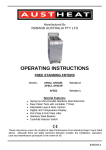
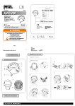
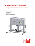
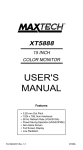
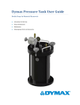
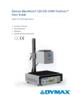
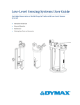
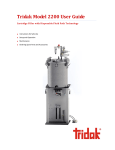
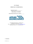
Tridak Model 1050 User Guide Syringe Filling System Instructions for Safe Use Setup and Operation Maintenance Ordering Spare Parts and Accessories 2 Model 1050 Syringe Filling System User Guide About Tridak – A Dymax Company Systems for fluid packaging. Tridak manufactures fluid packaging systems for a variety of industries including industrial, medical, dental, pharmaceutical, and food preparation. Tridak’s filling systems for syringes and cartridges provide significant productivity gains over manual and other more complicated and costly filling methods. The equipment is suited for all industry standard packaging as well as custom molded syringes and cartridges. Tridak possesses the capability to fabricate nozzles and multi-port dispensing manifolds that perfectly match the packages being filled. Single component and dual component materials can be packaged in seconds, one at a time, or in multiples for higher volume throughput. High-pressure filling equipment is available for packaging highly filled materials in tiny syringes or compoules. Please note that most filling system applications are unique. Tridak does not warrant the fitness of the product for the intended application. Any warranty applicable to the product, its application, and use is strictly limited to that contained in the Tridak standard Conditions of Sale. Tridak recommends that any intended application be evaluated and tested by the user to ensure that desired performance criteria are satisfied. Tridak is willing to assist users in their performance testing and evaluation. Data sheets are available for pressure pots upon request. Model 1050 Syringe Filling System User Guide Contents Introduction .................................................................................................................................................... 4 Introduction to the User Guide ....................................................................................................................................... 4 Where to Get Help .......................................................................................................................................................... 4 Safety.............................................................................................................................................................. 4 General Safety Considerations ........................................................................................................................................ 4 Specific Safety Considerations ......................................................................................................................................... 4 Personal Protective Equipment ....................................................................................................................................... 5 Product Overview ........................................................................................................................................... 5 Description of the Model 1050 Syringe Filling System .................................................................................................... 5 Special Features and Benefits of the Model 1050 ........................................................................................................... 5 Description of Main Components.................................................................................................................................... 5 Assembly and Setup ........................................................................................................................................ 7 Unpacking and Inspecting Your Shipment ....................................................................................................................... 7 Parts Included in the Model 1050 Syringe Filling System ................................................................................................ 7 Utilities Required ............................................................................................................................................................. 7 Preparing the System for Use .......................................................................................................................... 8 Install the Reservoir Support ........................................................................................................................................... 8 Install the Material Reservoir .......................................................................................................................................... 8 Connect the Material Reservoir Pressure Supply Tube ................................................................................................... 9 Operation ..................................................................................................................................................... 10 Preparing the Cartridge ................................................................................................................................................. 10 Loading the System ....................................................................................................................................................... 11 Pressurizing the System ................................................................................................................................................. 14 Depressurizing the System ............................................................................................................................................ 14 Set the Fill Amount for the Syringe Size ........................................................................................................................ 14 Priming the System........................................................................................................................................................ 15 Prepare the Syringes ..................................................................................................................................................... 15 Fill the Syringe ............................................................................................................................................................... 15 Model 830 Valve Adjustments ...................................................................................................................................... 16 Cleaning and Maintenance ........................................................................................................................... 16 System Cleaning ............................................................................................................................................................ 16 Spare Parts and Accessories .......................................................................................................................... 17 Replacement Parts/Accessories .................................................................................................................................... 17 Specifications ................................................................................................................................................ 17 System Specifications .................................................................................................................................................... 17 3 4 Model 1050 Syringe Filling System User Guide Introduction Introduction to the User Guide This guide describes how to assemble, use, and maintain the Model 1050 Syringe Filling System filling system safely and efficiently. Intended Audience Tridak prepared this user guide for experienced process engineers, technicians, and manufacturing personnel. If you are new to filling systems and do not understand the instructions, contact Tridak Application Engineering to answer your questions before using the equipment. Where to Get Help Additional resources are available to ensure a trouble-free experience with our products: ■ Detailed product information on www.tridak.com ■ Customer Support and Application Engineering teams are available in the United States, Monday through Friday, from 8:00 a.m. to 5:30 p.m. Eastern Standard Time. You can also email us at [email protected]. Please see the back cover of this user guide for worldwide contact information. Safety WARNING! If you use this filling system without first reading and understanding the information in this user guide, injury can result. To reduce the risk of injury, read and ensure you understand the information in this user guide before assembling and operating a Tridak filling system. General Safety Considerations All users of Tridak equipment should read and understand this user guide before assembling and using the equipment. Specific Safety Considerations Using Safe Operating Pressures Pressurizing the components in the dispensing system beyond the maximum recommended pressure can result in the rupturing of components and serious personal injury. To minimize the risk of rupturing components and injury, do not exceed the maximum operating pressure of the components in your filling system. (See system specifications on page 17) Model 1050 Syringe Filling System User Guide Preventing Injection Injury Discharging fluids or compressed air with a dispensing tip against your skin can cause very serious injection injury. To minimize the risk of injection injury, do not place the dispensing tip in contact with your skin. Personal Protective Equipment Operators are recommended to wear any personal protective equipment specified by their company’s safety policy for the materials used during filling. Personal protective equipment should be in place and used at all times before pressurizing the system and when handling any potentially hazardous materials. Product Overview Description of the Model 1050 Syringe Filling System The Model 1050 syringe filling system is designed to quickly fill plunger-style syringes, one at a time, quickly and accurately from a material reservoir. The system can be used with a number of different material reservoirs including cartridge reservoirs, bottle reservoirs, and pail reservoirs. The system utilizes a Model 830 disposable fluid path valve to make material changeover fast and easy, while eliminating most crosscontamination. The disposable fluid path can be fitted with a series of adapters to fill Luer-Lock and Oral tip syringe types. Special Features and Benefits of the Model 1050 This machine features several design features to make filling simple, quick and clean, including: Disposable fluid path valve with disposable wetted parts that eliminate material contamination and minimize clean-up and maintenance Disposable fluid path can be capped and remain attached to the material cartridge for storage Adjustable suck-back feature allows for a clean dispense of stringy and tacky materials Material reservoir pressure regulator to control the reservoir pressure used for filling Fills various syringes including 0.5, 1, 3 and 5 ml (up to 60 ml) syringes with pre-inserted plunger; tooling nozzles are available for both Luer Lock or Oral tips. Adjustable pneumatic stop assures accurate fills Foot-switch for hands-free fill cycle activation Small footprint; Dimensions (L x W x H) – 23.6 in x 12 in x 25 in (60 cm x 30.48 cm x 63.50 cm) Description of Main Components The main components in the Model 1050 Syringe Loader filling system include: 1. Air Precision Regulator – The air precision regulator enables you to precisely control pressure in the fluid reservoir. The air precision regulator includes: the air 5 6 Model 1050 Syringe Filling System User Guide 2. a. Pressure gauge that displays the pressure in the fluid reservoir. A 0- to 100-psi (0- to 6.9-bar) pressure gauge is installed on the air regulator. b. Pressure control knob that enables you to adjust the pressure of the air entering the reservoir. 5-45psi recommended for most applications. Compressed Air Line – The air line consists of blue polyurethane tubing designed for compressed air use. 3. Model 830 Valve – A disposable fluid path valve used to dispense material from the material reservoir. This valve features suck-back, allowing drip-free dispensing from fill-to-fill. 4. Fluid Path – The fill tube and fittings used to deliver fluid material from bulk cartridges 5. Tube Support – Supports the disposable fluid path during dispensing and allows the valve pistons to to syringes. It is constructed of black, light-blocking polyethylene tubing compatible with many types of commercial and medical fluids. compress the fluid path as needed to control fluid flow and suck-back. 6. Reservoir Retainer or Reservoir Tank – The reservoir retainers and tanks hold fluid reservoirs. Reservoir retainers accept cartridge reservoirs. Reservoir tanks accept bottle and pail reservoirs. Figure 1. Main Components of the Model 1050 Syringe Filling System Material Reservoir Support Material Reservoir Pressure Supply Model 830 Dispensing Valve Flow Control Air Precision Regulator Disposable Fluid Path Compressed Air Line Inlet (60-90 psi) Foot Switch Tube Support Assembly Valve Mounting Screw Fill Stop Model 1050 Syringe Filling System User Guide Assembly and Setup Unpacking and Inspecting Your Shipment When your system arrives, inspect the boxes for damage and notify the shipper of box damage immediately. Open each box and check for equipment damage. If parts are damaged, notify the shipper and submit a claim for the damaged parts. Contact Tridak so that new parts can be shipped to you immediately. Check that the parts included in your order match those listed below. If parts are missing, contact your local Tridak representative or Tridak Customer Support to resolve the problem. Parts Included in the Model 1050 Syringe Filling System Model 1050 with Foot Switch [1] Allen Key Kit [2] Airline Kit for Reservoir and Model 1050 [3] Tube Assemblies – Luer Female [4] 0.32” Bleed Wire with Pull Ring [5] Stopper Pin (for use with plunger-less syringes) [6] Rod Assembly [7] Reservoir [8] Model 1050 User Manual Figure 2. Unpacking Diagram Utilities Required AIR: Clean, dry, non-lubricated air operating pressure of 60 – 90 psi 7 8 Model 1050 Syringe Filling System User Guide Preparing the System for Use Install the Reservoir Support 1. Place the reservoir support on top of the screw hole in the left side of the system base. 2. Using the screw and washer provided, place screw up with the washer through hole in base and attach to reservoir support. Tighten the screw until the reservoir support is secure (Figure 3). Figure 3. Reservoir Support Installation Install the Material Reservoir 1. Slide the Material Reservoir Retainer (Figure 4, D) over the top of the Reservoir Support (Figure 4, B). 2. Position the Material Reservoir Retainer on the Reservoir Support so that the bottom of the Retainer is approximately 2 inches above the top of the Back Plate. 3. Using the Height Adjustment Handle (Figure 4, C), tighten the set screw until the Material Reservoir Retainer does not move. Model 1050 Syringe Filling System User Guide 9 Connect the Material Reservoir Pressure Supply Tube 1. Connect the material reservoir’s Pressure Supply (Figure 4, F) to the Precision Air Regulator (Figure 4, G). 2. Connect the opposite end of the Material Reservoir Pressure Supply to the Material Reservoir Air Inlet. NOTE: If your system is using a cartridge retainer, the Material Reservoir Air Inlet (Figure 4, A) is located in the center of the cartridge retainer’s cap. Figure 4. Syringe Filler with 20 oz Cartridge Retainer (Rear View) B – Reservoir Support A –Material Reservoir Air Inlet C – Height Adjustment Handle D – Reservoir Retainer F – Material Reservoir Pressure Supply G – Precision Air Regulator E – Fluid Path H – System Pressure Inlet 10 Model 1050 Syringe Filling System User Guide Operation Preparing the Cartridge 1. Place pre-packaged, sealed cartridge upright on a flat, stable working surface (Figure 5). 2. With the Nozzle up, remove the Colored Cap, and quickly insert the Mating Fitting from the Disposable Fluid Path (Figure 6). Tighten firmly. 3. Ensure the Fluid Path is sealed with a Luer Fitting and Cap before transporting or loading the Cartridge into the Reservoir Retainer. NOTE: Low-viscosity fluids may require Teflon® wrap on threads. Figure 5. Cartridge with Cap Installed Figure 6. Cartridge with Fluid Path Installed Remove Cap Nozzle Fluid Path Mating Fitting Model 1050 Syringe Filling System User Guide Loading the System Fill Material Reservoir 1. Remove the Reservoir Retainer Cover by removing the Star Nuts and Cover. Ensure the Retainer is free and clear of any previously placed cartridges or packaging. 2. Insert the Cartridge/Fluid Path Assembly into the Reservoir Retainer. 3. Guide the Fluid Path downward, passing through the bottom of the Reservoir. 4. Press the Cartridge firmly into place until seated. 5. Replace the Reservoir Retainer Cover and tighten evenly and securely with Star Nuts until the Cover forms a solid seal around the Cartridge. If you experience any trouble, please contact Tridak Customer Service. Figure 7. Material Reservoir Exploded Diagram Star Nut Star Nut Cover O-Ring Cartridge Cartridge Retainer Cartridge Mating Fitting Fluid Path 11 12 Model 1050 Syringe Filling System User Guide Install the Fluid Path 1. Remove the four 8-32 x 0.75" Screws (Figure 9) that hold the Tube Support and the Valve Body together. 2. Evenly loosen the two Luer Block Clamp Screws (Figure 8) enough to slip the Luer Tip Cap through the opening. Position the Fluid Path in the Luer Block Clamp so that the left edge of the Luer Block Clamp just catches the white Luer Tip. 3. Evenly tighten the two Luer Block Clamp Screws. 4. Install the Fluid Path and the Tube Support to the Model 830 Valve (Figure 8). The Tube Support has two access holes for the over-pinch and suck-back adjusts at the top of the cover and must be installed in the correct orientation. Evenly tighten the two Tube Support Removal Screws. Figure 8. Luer Block Clamp Luer Block Clamp Luer Tip Luer Block Clamp Screws Model 1050 Syringe Filling System User Guide Figure 9. Fluid Path Installation 8-32 x 0.75" Screws (4) Washers (4) Tube Support Assembled Unit Fluid Path / Tubing Over-Pinch Adjust Suck-Back Adjust Valve Body NOTE: Follow the same assembly and replacement for the following filling configurations: T15225 TUBE ASSEMBLY, LUER FEMALE 13 14 Model 1050 Syringe Filling System User Guide Pressurizing the System NOTE: Before operating the machine at the beginning of each run, check that all tubes, covers, guards, and safety devices are properly installed for operation. The system is energized when a compressed air supply is connected to the System Pressure Inlet. WARNING! Do not exceed 90 psi system pressure. The following steps must be completed in order to safely pressurize the system. If these steps are not followed correctly, it is possible to create a situation that could result in a material spill through the Luer Tip. 1. Ensure that the Fluid Path is correctly installed in the Luer Support and the Tube Support. 2. Check that the Luer Clamp and the Tube Support are tightened down fully. 3. Ensure the Luer Tip Cap is installed and tightened onto the Luer Tip. 4. Disconnect the Material Reservoir Pressure Supply from the Material Reservoir Air Inlet. 5. Connect a Compressed Air Supply (max 90 psi) to the System Pressure Inlet. 6. Set the Precision Air Regulator to 0 psi. 7. Connect the Material Reservoir Pressure Supply to the Material Reservoir Air Inlet. 8. Set the Precision Air Regulator to 10 psi starting pressure. 9. Check for any material leaks occurring at the Luer Tip or at the Material Cartridge and depressurize the system if any leaks are present. Depressurizing the System 1. Ensure the Luer Tip Cap is installed and tightened onto the Luer Tip. 2. Set the Precision Air Regulator to 0 psi. 3. Disconnect the Material Reservoir Pressure Supply from the Material Reservoir Air Inlet. 4. Disconnect the Compressed Air Supply from the System Pressure Inlet. Set the Fill Amount for the Syringe Size For the required syringe size, use the scale to set the fill volume by adjusting the syringe fill stop to the desired location. 1. Disconnect the Compressed Air Supply from the System Pressure Inlet. 2. By hand, set the Syringe Plunger to the desired fill/mL volume. 3. Twist or slide the Syringe and extended Plunger on to the Nozzle/Needle/Luer Lock Tip of the Fluid Path. 4. Loosen the Syringe Fill Adjustment Lock by loosening the bottom two Allen Cap Screws (Figure 10). 5. Ensure the Syringe Fill Stop is “at rest”, and not extended. Model 1050 Syringe Filling System User Guide 6. Move the Syringe Fill Stop to the position where it immediately touches the extended Syringe Plunger. 7. From this position, gently slide the Syringe Fill Stop 5 scale lines away from the Syringe Plunger. The Syringe Fill Stop will retract to this position when each syringe reaches the desired fill volume. 8. Re-tighten the Syringe Fill Stop using Allen Cap Screws. Figure 10. Model 1050 with Syringe Inserted Syringe Piston Syringe Plunger Syringe Fill Stop Luer Tip Syringe Allen Cap Screws Priming the System During initial setup and when changing material cartridge reservoirs, air must be purged from the disposable fluid path/fill tube to prevent accidental spills and introducing bubbles into syringes. Prime the system by running material through the fluid path until a constant, solid flow of material is achieved. Depending on material, reducing the pressure by 5-15 psi will make it easier to see the air being purged. Prepare the Syringes Before filling each syringe, ensure the syringe plunger is fully inserted to the tip of the syringe to remove most of the air from the empty syringe. Fill the Syringe 1. Remove the Cap from the Luer Tip. 2. Load the required Syringe size by threading it onto the Luer Tip (Figure 10). 3. Make sure all hands and fingers are clear of the machine. Press and hold the Foot Switch to activate the filling cycle. 4. Release the Foot Switch when the Syringe Plunger touches the Syringe Fill Stop. 5. Remove the Syringe from the Luer Tip. 6. Cap the Syringe Tip and the Syringe End as needed. 7. Repeat above steps 2 through 6 for each additional syringe needed. 15 16 Model 1050 Syringe Filling System User Guide Model 830 Valve Adjustments The 830 valve highlights a suck-back feature to prevent oozing and dripping between syringes. Depending on the type of fluids used, the suck-back feature will require adjustment. Batch-to-batch adjustment is recommended. If material drips, suck-back should be increased. If there are air bubbles in the syringe, decrease the amount of suck-back. Adjusting Suck-Back Position (Front) The Adjustment Screw is located on the top face of the valve. To increase suck-back, loosen the adjustment screw counter-clockwise. To decrease suck-back, tighten the adjustment screw clockwise. (Figure 11) Figure 11. Suck-Back Adjustment Screw Increase Suck-Back (Counter-Clockwise) Decrease Suck-Back (Clockwise) Cleaning and Maintenance System Cleaning Switching to a Different Material The disposable fluid path in the Model 830 valve allows for quick and easy material changeover. To switch your system over from dispensing one material to dispensing a new material, simply replace the fluid path tube in the dispensing valve. You will also need to replace the material reservoir on the system. The new material can be placed in a new material reservoir or the existing reservoir can be cleaned and the material replaced. Model 1050 Syringe Filling System User Guide Spare Parts and Accessories Replacement Parts/Accessories Part Number Item Air Lines & Regulators T16789 Air Supply Line T18297 Regulator Assembly Reservoir Cartridge Kits T18306 20oz Cartridge Assembly HDPE T18307 32oz Cartridge Assembly HDPE Luer Block Parts T18294 Modified Thumb Screw 10-32 & V Block Top, 1050 Model 830 Parts T18196 T18304 Valve, Model 830 Spare Parts Kit Includes: Modified 1050 Thumb Screw, Model 830 Thumb Screw, 830 Hardware Kit Tube Assemblies T15225 Tube Assembly, Luer Female T18305 Tube Assembly, No Tip (For Use with Custom Tooling) Misc. T18218 Bleed Wire with Pull Ring T16603 Foot Switch Assembly Pneumatic, 1000 T18296 Stopper Assembly Specifications System Specifications Materials of Construction—Wetted Parts ■ Dispensing valve = No wetted parts. ■ Fluid tubing = light blocking, black, polyethylene ■ Fluid tubing fittings = acetal ■ Fluid cartridge reservoirs = HPDPE ■ Fluid cartridge reservoir piston = HDPE 17 18 Model 1050 Syringe Filling System User Guide Operating Specifications Recommended compressed air supply pressure to air filter/regulator = 60 psi min (4.1 bar) Maximum pressure setting at air filter/regulator = 100 psi (6.9 bar) Compatible material viscosity range: 1 – 60,000 cP Reservoir Retainer/Tank Sizes Cartridge retainers hold 20 and 32-oz (550 and 900-mL) reservoirs 1 gallon (3.8 L) bulk feed reservoir option available: inquire with Tridak Customer Service Air Precision Regulator Pressure Gauges Pressure gauge installed from factory = 0 to 100 psi (0 to 6.9 bar) Dimensions Dimensions (L x W x H) – 23.6 in x 12 in x 25 in (60 cm x 30.48 cm x 63.50 cm) Model 1050 Syringe Filling System User Guide Figure 12. Model 1050 Syringe Loader Dimensions 19 © 2015 Tridak LLC – A Dymax Company. All rights reserved. All trademarks in this guide, except where noted, are the property of, or used under license by Tridak LLC or Dymax Corporation, U.S.A. Please note that most filling system applications are unique. Tridak does not warrant the fitness of the product for the intended application. Any warranty applicable to the product, its application and use is strictly limited to that contained in Tridak’s standard Conditions of Sale. Tridak recommends that any intended application be evaluated and tested by the user to ensure that desired performance criteria are satisfied. Tridak is willing to assist users in their performance testing and evaluation. Data sheets are available for pressure pots upon request. MAN074 2/17/2015 Dymax Corporation 860.482.1010 | [email protected] www.dymax.com | www.tridak.com Dymax Oligomers & Coatings 860.626.7006 | oligomers&[email protected] www.dymax-oc.com Dymax UV Adhesives & Equipment (Shanghai) Co Ltd +86.21.37285759 | [email protected] www.dymax.com.cn Dymax Asia (H.K.) Limited +852.2460.7038 | [email protected] www.dymax.com.cn Dymax Korea LLC +82.2.784.3434 | [email protected] www.dymax.com/kr Dymax Europe GmbH +49 (0) 611.962.7900 | [email protected] www.dymax.de Dymax UV Adhesives & Equipment (Shenzhen) Co Ltd +86.755.83485759 | [email protected] www.dymax.com.cn Dymax Asia Pacific Pte. Ltd. +65.6752.2887 | [email protected] www.dymax-ap.com