1
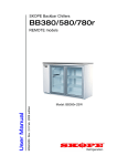
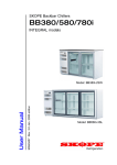
BB380r-2 Door
BB580r-3 Door
BB780r-4 Door
SKOPE Backbar Remote Chillers
MAN0706 Rev. 1.0 Dec. 2003 edition
Installation and Operating Instructions
Horizontal Display and Storage
Model: BB380r-2SW
CONTACT ADDRESSES
Designed and Manufactured by
New Zealand
SKOPE INDUSTRIES LIMITED
PO Box 1091, Christchurch
New Zealand
Freephone: 0800 947 5673
Fax: (03) 983 3896
E-mail: [email protected]
Website: www.skope.co.nz
Australia
SKOPE AUSTRALIA PTY LTD
A.C.N. 000 384 270
PO Box 7543, Baulkham Hills B.C.
NSW 2153, Australia
Freephone: 1800 121 535
Fax: 1800 121 533
E-mail: [email protected]
Website: www.skope.com.au
Middle East
SKOPE INDUSTRIES MIDDLE EAST
PO Box 37663, Dubai
United Arab Emirates
E-mail: [email protected]
BB380r-2, BB580r-3, BB780r-4
SKOPE Backbar Remote Chillers
i
BB380r-2, BB580r-3, BB780r-4
SKOPE Backbar Remote Chiller
Installation and Operating Instructions
MAN0706
Rev. 1.0 Dec. 2003 edition.
Published by
SKOPE Industries Limited,
Christchurch, New Zealand.
Copyright © 2003
SKOPE Industries Limited.
All rights reserved.
SKOPE and CYCLONE are
registered trademarks of
SKOPE Industries Limited.
SKOPE Industries Limited reserve the
right to alter specifications without
notice.
ii
BB380r-2, BB580r-3, BB780r-4
SKOPE Backbar Remote Chillers
TABLE OF CONTENTS
1
SPECIFICATIONS
1.1
Cabinet and Refrigeration Unit . . . . . . . . . . . . . . . . . . . . . . . 6
2
INSTALLATION
2.1
Positioning of Machine . . . . . . . . . . . . . . . . . . . . . . . . . . . . . 7
2.2
Refrigeration System . . . . . . . . . . . . . . . . . . . . . . . . . . . . . . . 9
3
OPERATION
3.1
Safety Information . . . . . . . . . . . . . . . . . . . . . . . . . . . . . . . . 11
3.2
Operation of Machine . . . . . . . . . . . . . . . . . . . . . . . . . . . . . 12
3.3
Loading . . . . . . . . . . . . . . . . . . . . . . . . . . . . . . . . . . . . . . . . 12
3.4
Cleaning . . . . . . . . . . . . . . . . . . . . . . . . . . . . . . . . . . . . . . . 13
3.5
Servicing . . . . . . . . . . . . . . . . . . . . . . . . . . . . . . . . . . . . . . . 13
4
ELECTRONIC CONTROLLER
4.1
Controller Display . . . . . . . . . . . . . . . . . . . . . . . . . . . . . . . . 14
4.2
Controller Operation . . . . . . . . . . . . . . . . . . . . . . . . . . . . . . 15
4.3
Programming Controller . . . . . . . . . . . . . . . . . . . . . . . . . . . 16
4.4
Parameters . . . . . . . . . . . . . . . . . . . . . . . . . . . . . . . . . . . . . 18
4.5
Display Alarms. . . . . . . . . . . . . . . . . . . . . . . . . . . . . . . . . . . 19
BB380r-2, BB580r-3, BB780r-4
SKOPE Backbar Remote Chillers
iii
1 SPECIFICATIONS
1.1
Cabinet and Refrigeration Unit
Cabinet Construction
Finish:
Insulation:
Stainless steel or powdercoated galvanised steel
50mm thick, polyurethane foam
Cyclo-iso Pentane blowing agent: C5H10/C5H12
Dimensions
Models:
Doors:
Height:
Width:
Depth (Solid Back):
Depth (Pass-Thru):
Floor area:
Internal volume:
BB380r-2
BB580r-3
2 Door
3 Door
920mm*
920mm*
1355mm
1915mm
590 - 600mm (with bench top)
655 - 670mm (with bench top)
BB780r-4
4 Door
920mm*
2475mm
0.81m2
380 litres
1.48m2
780 litres
1.14m2
580 litres
Electrical
Power supply:
Run Amps:
Interior light:
220-240 V a.c. 50 Hz, single phase power supply
See rating label inside cabinet
1 x 36 Watt
1 x 58 Watt
1 x 58 Watt
Refrigeration Unit
Product temp:
Rated ambient:
Evap. capacity
Evaporator:
TX valve - R134a
TX valve - R404A
TX valve - R22
Orifice:
Refrigeration tail Ø:
Drain Ø:
+1°C to +4°C
32°C at 65% RH
480 Watts
615 Watts
850 Watts
CLS9902R
VAL7923
VAL9641
VAL9643
‘0X’ REF9761 ‘00’ REF7596
‘00’ REF7596
Liquid line: 1/4” Suction line: 3/8”
19mm O.D.
* Height excludes castors or legs
6
BB380r-2, BB580r-3, BB780r-4
SKOPE Backbar Remote Chillers
2 INSTALLATION
2.1 Positioning of Machine
Castors / Legs
If your SKOPE Backbar chiller has been supplied with either the
optional adjustable height castors or adjustable legs (packed with
the cabinet), they should be fitted to the base of the cabinet before
final positioning of the chiller.
Siting chiller
When installing the chiller it is important to consider the location and
physical environment where the chiller is to be positioned. When
siting the chiller, avoid direct sunlight and warm draughts etc.
Maximum recommended operating ambient temperature is 32°C at
65% RH, and for tropical machines is 40°C at 75% RH.
Adequate allowance should be made for door opening. The chiller
must be positioned on a level surface for the doors to shut and seal
correctly, and to prevent the condensate tray from overflowing.
Shelves
Remove all packaging material from the shelves. Clip the shelf
support brackets into the shelf support strips, at the desired heights,
and fit the shelves.
Shelves may be positioned at different heights to suit various
products. Always ensure that the shelf clips are securely engaged in
each of the shelf support strips. Shelf support strips are marked ‘+’
for easy location of shelf clips.
BB380r-2, BB580r-3, BB780r-4
SKOPE Backbar Remote Chillers
7
2 INSTALLATION
Mains flex
The mains flex exits below the refrigeration unit front cover. Initial
retrieval of the mains flex is from inside the refrigeration unit
compartment, behind the unit front cover. To retrieve the mains flex:
1. Open the unit front cover: firstly undo the fixing screw at bottom
of cover, then lift the cover up from the bottom and swing open.
2. Pull the mains flex fully out from the unit compartment, and
remove the rubber band.
3. Push the unit end of flex into the grey plastic clip beside the
front cover bottom hinge, and close the plastic clip over the
flex, ensuring it is held firmly in place.
4. The mains flex can now be run under the cabinet, and plugged
into a power socket
5. Close the unit front cover: by lifting the cover up from the
bottom and pushing firmly closed. Remember to refit the
bottom fixing screw.
Bottom Hinge
Cabinet Base
Unit Front Cover
Flex Clip
Mains Flex
Figure 1: Mains Flex
8
BB380r-2, BB580r-3, BB780r-4
SKOPE Backbar Remote Chillers
2 INSTALLATION
2.2 Refrigeration System
Drain
A 500mm long, 19mm O.D. PVC drain hose is supplied. All drainage
is to conform to local regulations, covering removal of condensate to
waste water. Ensure drain is trapped with adequate fall. Venting the
drain may be required for a restrictive run.
Refrigeration lines
A 1/4” liquid line, and 3/8” suction line are provided to attach pipe
lines to. The suction lines must be insulated.
NOTE: The electronic controller supplied with the cabinet can switch
a solenoid. No solenoid is supplied with the remote unit.
Refrigeration Practice
Installation must be performed by a refrigeration tradesperson, to an
appropriate standard complying with all local regulations.
Performance depends on the overall installation (including
condensing unit). Cabinet suitability must always be quantified for
the application. The final responsibility for condensing unit
performance and component selection rest with the installer. The
installer must check matters such as:
•
•
•
•
•
•
•
Heat load
Refrigeration load
Variable operating conditions (usage, ambient, humidity)
Refrigeration pipe sizing
Refrigeration pipe length (distance, elevation, pressure drop)
Location and ventilation (cabinet and condensing unit)
Drainage
BB380r-2, BB580r-3, BB780r-4
SKOPE Backbar Remote Chillers
9
2 INSTALLATION
• Power supply
• Unit is fully evacuated prior to charging
• All cabinet penetrations are sealed
Electrical
The cabinet is supplied with a 3-core 10 Amp mains flex and plug.
The cabinet lighting and centre pillar heater elements are protected
by a 3 Amp fuse, located in the unit junction box.
If a solenoid is fitted and controlled by the electronic controller, the
solenoid will need connected to the connector block inside the unit
junction box.
Unit Pipework Cover
Refrigeration Unit Compartment
Suction Line
Drain Tube
Rear of Cabinet
Liquid Line
Figure 2: Refrigeration Pipework
10
BB380r-2, BB580r-3, BB780r-4
SKOPE Backbar Remote Chillers
3 OPERATION
3.1 Safety Information
When using any electrical appliance, safety precautions should
always be observed. Read these instructions carefully, and retain for
future reference.
• Do not use this appliance for other than its intended use.
• Only use this appliance with voltage specified on the rating label.
• Ensure adequate ventilation of SKOPE refrigeration unit.
• Be careful not to touch moving parts and hot surfaces.
• Do NOT cover the grilles or block the entry or exhaust of airflow
by placing objects up against the refrigeration unit.
• Do NOT probe any opening.
• Regulations require that all electrical work be carried out by
authorised persons. For your own safety and that of others,
ensure this is done.
• If the refrigeration unit is required to be installed or removed
from the cabinet, ensure all necessary safety precautions are
observed.
Warning:
Do NOT overload power supply.
Caution:
Disconnect machine mains power supply before attempting to
perform any electrical service or maintenance.
BB380r-2, BB580r-3, BB780r-4
SKOPE Backbar Remote Chillers
11
3 OPERATION
3.2 Operation of Machine
Plug in machine and check operation of the refrigeration unit and
lights. The electronic controller and evaporator fan motor should
operate initially. Note: If the solenoid valve is fitted, and operated by
electronic control, then the solenoid should open when compressor
indicator is shown.
Checking operation
• The solenoid / compressor relay should switch off when cabinet
internal temperature reaches approximately +1°C, and on again
at approximately +4°C. The internal cabinet air will continue to
circulate at all times.
• The light switch, located next to the electronic controller on the
refrigeration unit front cover, activates the cabinet interior
lighting and can be switched on or off as required.
• For efficient operation, ensure the door gaskets form a good
seal with the cabinet.
3.3 Loading
For even cooling and efficient operation, allow air space around
packages etc. Do not allow products to overhang the front of shelf
as this could prevent the door from shutting or cause glass
breakage.
Important:
Leave air space above product on the top shelf, as well as a
gap of approximately 50mm next to the return air grille
between the cabinet interior and the refrigeration unit
compartment.
12
BB380r-2, BB580r-3, BB780r-4
SKOPE Backbar Remote Chillers
3 OPERATION
3.4 Cleaning
When necessary, wash both interior and exterior of cabinet with
soapy water. Exterior of cabinet may be waxed with automobile
polish for extra protection. Ensure the machine is disconnected from
the mains power supply before washing the cabinet with water.
Do not wipe the sealant off the swing door gaskets, as the sealant
ensures the door gaskets form a good seal with the cabinet.
Caution:
Disconnect machine from mains power supply before washing
the cabinet with water.
3.5 Servicing
Servicing should be carried out by an authorised service agent.
Detailed service and spares information is available in the SKOPE
Backbar Remote Operating and Service Manual - P/No: MAN0707.
BB380r-2, BB580r-3, BB780r-4
SKOPE Backbar Remote Chillers
13
4 ELECTRONIC CONTROLLER
4.1 Controller Display
5
6
3
7
4
1
Figure 3: Controller Display
8
Item
Key
2
Function
1
SET: Press to display target set point. In programming mode it selects
a parameter or confirms an operation
2
DEFROST: Press to start a manual defrost
3
UP: Press to see the maximum stored temperature. In programming
mode it browses the parameter codes, or increases the displayed value
4
DOWN: Press to see the minimum stored temp. In programming mode
it browses the parameter codes, or decreases displayed value
5
Compressor ON indicator
6
Defrost cycle ON indicator
7
Set Point displayed indicator
8
Decimal point indicator
Key Combinations:
+
Press to lock and unlock the keypad
+
Press to enter the programming mode
+
Press to return to the room temperature display
Table 1: Controller Operation
In normal operating conditions the controller can permanently
display one of the following:
14
BB380r-2, BB580r-3, BB780r-4
SKOPE Backbar Remote Chillers
4 ELECTRONIC CONTROLLER
1. Internal cabinet temperature (standard parameter ‘Lod’ = P1)
2. Setpoint (parameter ‘Lod’ = SP)
3. Condensing temperature (parameter ‘Lod’ = P2)
Meaning of LEDs
Each LED function is described in the following table:
LED
Mode
Function
ON
Compressor enabled
Flashing
Programming phase (flashing with
Anti-short cycle delay enabled
ON
Defrost enabled
Flashing
Programming phase (flashing with
Drip time in progress
ON
The Set Point is displayed
)
)
Table 2: LED Functions
4.2 Controller Operation
The SKOPE electronic controller controls and displays the cabinet
temperature. The preset temperature setting controls internal air
temperature between 1°C and 4°C. For compressor protection the
control has built in minimum off cycle time of 3 minutes, and features
regular timed defrost cycles (compressor off, evaporator fans on).
Probe One is fitted to a bracket in the return evaporator airflow. This
probe is used for both temperature control and display.
Probe Two is cable tied in place with an insulated cover. This probe
is not active.
BB380r-2, BB580r-3, BB780r-4
SKOPE Backbar Remote Chillers
15
4 ELECTRONIC CONTROLLER
4.3 Programming Controller
The controller keypad must always be locked, to prevent unauthorised modification.
To unlock the keypad (to modify parameters)
Press both the UP and DOWN keys until ‘Pon’
is displayed.
How to lock the keypad
1. Press and hold both the UP and DOWN
keys for more than 3 seconds.
2. The ‘PoF’ message will be displayed and
the keypad will be locked. At this point it will be possible only to
see the Set Point or maximum or minimum temperature stored.
3. If a key is pressed for more than 3 seconds, the ‘PoF’ message
will be displayed.
To display the Set Point
Press, and immediately release the SET key. The
display will show the Set Point value, and the Set Point
LED will be highlighted.
To change the Set Point
1. Push and hold the SET key for
more than 2 seconds.
2. The value of the Set Point will be
displayed, and the
LED will start blinking.
3. To change the Set value, push the UP or DOWN keys.
4. To memorise the new Set Point value, push the SET key again
or wait 15 seconds.
16
BB380r-2, BB580r-3, BB780r-4
SKOPE Backbar Remote Chillers
4 ELECTRONIC CONTROLLER
To start a manual defrost
Push and hold the DEFROST key for more than 2
seconds.
To change a parameter value
1. Enter the programming mode by
pressing and holding both the
SET and DOWN keys for 3 sec.
(
and
start flashing).
2. Select the required parameter.
3. Press the SET key to display the Set value (now only the
LED is flashing).
4. Press the UP or DOWN keys to change the Set value.
5. Press the SET key to store the new value and move to the
following parameter.
6. To exit: Press both the SET and UP keys, or wait 15 seconds
without pressing any keys.
7. To lock in new parameter value: after one minute operation,
disconnect and reconnect cabinet into the mains power supply.
NOTES:
1. The Set value is stored even when the procedure is exited by
waiting for the time-out to expire.
2. Dependent on customer requirements, the SKOPE electronic
controller has different parameter configurations.
Parameter configuration 160 = Beverage, and 170 = Food.
To establish correct controller parameter configuration, see
label on controller housing.
BB380r-2, BB580r-3, BB780r-4
SKOPE Backbar Remote Chillers
17
4 ELECTRONIC CONTROLLER
4.4 Parameters
Parameters
Beverage
Food
160
170
SET POINT PARAMETERS
Set
2
1
Hy
2
2
LS
+1
-1
US
15
5
PROBE PARAMETERS
Ot
-0.7
0
OE
0
0
CONTROL PARAMETERS
OdS
0
0
AC
3
3
DISPLAY PARAMETERS
CF
°C
°C
rES
dE
in
LoD
P1
P1
DEFROST PARAMETERS
IdF
6
6
MdF
12
12
dFd
dEF
dEF
dAd
20
20
ALARM PARAMETERS
ALc
Ab
Ab
ALU
12
7
ALL
-2
-2
AtH
1
1
ALd
240
120
dAO
24
24
tbA
n
n
PA2
58
58
AU2
65
65
ACH
5
5
dL2
2
2
dA2
0
0
AOP
CL
CL
OTHER PARAMETERS
dP1
dP2
rEL
Ptb
Display
Range
Description of Parameter
LS to US
0.1°C to 25.5°C
Set Point
Differential
DO NOT ADJUST
DO NOT ADJUST
DO NOT ADJUST
DO NOT ADJUST
1 to 120 hours
0 to 255 minutes
Interval between defrost cycles
Maximum length for defrost
DO NOT ADJUST
DO NOT ADJUST
ALL to 150°C
Maximum temperature alarm
-50°C to ALU
Minimum temperature alarm
DO NOT ADJUST
DO NOT ADJUST
Table 3: Controller Parameters
18
BB380r-2, BB580r-3, BB780r-4
SKOPE Backbar Remote Chillers
4 ELECTRONIC CONTROLLER
4.5 Display Alarms
A flashing LED indicates an alarm. The following is a list of the alarm
displays:
Alarm
Description
Stage ONE - Maintenance required:
Immediately attend condenser (for auto alarm reset).
Stage TWO - Refrigeration Shut-Down:
Condenser over-temperature has shut-down system and
cabinet lighting. Attend condenser. To reset alarm, cabinet
must be replugged into power supply. For repeat alarms,
contact an authorised service agent.
Faulty Ambient probe (internal cabinet - return air)
Faulty High Temperature probe (condenser)
Internal cabinet - LOW temperature alarm
Internal cabinet - HIGH temperature alarm
Table 4: Controller Display Alarms
Note: Refrigeration system and cabinet lighting shut down with ‘P1’,
‘P2’ and ‘CSd’ alarms.
Alarm Recovery
• Condenser over temperature alarm ‘COH’ recovers when the
condenser is either cleaned or cools down.
• Condenser alarm ‘CSd’ temperature recovers by replugging the
cabinet power supply (or isolation switch). In this case, all the
alarms are reset.
BB380r-2, BB580r-3, BB780r-4
SKOPE Backbar Remote Chillers
19