1
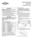
Owner and Installation
Manual
Mobile Link™ Unit
™
*
THIS PRODUCT CAN BE INSTALLED BY THE OWNER. HOWEVER, IF
UNCOMFORTABLE WITH THE SKILLS OR TOOLS REQUIRED, THE
MANUFACTURER RECOMMENDS TO HAVE A QUALIFIED ELECTRICIAN
OR CONTRACTER PERFORM THE INSTALLATION.
This manual should remain with the Mobile Link unit.
FOR INSTALLATION ASSISTANCE CONTACT: 1-855-GEN-VIEW
Table of Contents
FCC Compliance....................................................1
Section 1: Safety...................................3
1.1: General Safety............................................4
1.2: General Safety Hazards..............................5
1.3: Electrical Hazards.......................................6
1.4: Explosion Hazards......................................7
Section 2: General Information ............8
2.1: Introduction.................................................8
2.2: Applications.................................................8
2.3: Information Screens....................................9
Section 3: Installation..........................12
3.1: Installation.................................................12
Section 4: Actition...............................22
Section 5: Maintenance.......................22
5.1: Cleaning....................................................22
Section 6: Troubleshooting.................23
Section 7: Notes...................................24
WARNING!
California Proposition 65
This product contains or emits chemicals known to the state of California to cause cancer,
birth defects, and other repoductive harm.
Compliance Statement (Part 15.19)
This device complies with Part 15 of the FCC Rules.
Operation is subject to the following two conditions:
1.This device may not cause harmful interference.
2.This device must accept any interference received, including interference that may cause undesired operation.
Warning (Part 15.21)
Changes or modifications not expressly approved by the party responsible for compliance could void the user's authority to operate the equipment.
FCC Interference Statement (Part 15.105 (b))
This equipment has been tested and found to comply with the limits for a
Class B digital device, pursuant to Part 15 of the FCC Rules. These limits
are designed to provide reasonable protection against harmful interference in a residential installation. This equipment generates, uses and can
radiate radio frequency energy and, if not installed and used in accordance with the instructions, may cause harmful interference to radio communications. However, there is no guarantee that interference will not
occur in a particular installation. If this equipment does cause harmful
interference to radio or television reception, which can be determined by
turning the equipment off and on, the user is encouraged to try to correct
the interference by one of the following measures:
•
•
•
Reorient or relocate the receiving antenna.
Increase the separation between the equipment and receiver.
Connect the equipment into an outlet on a circuit different from that to
which the receiver is connected.
Mobile Link
1
•
Consult the dealer or an experienced radio/TV technician for
help.
To comply with FCC/IC RF exposure limits for general population /
uncontrolled exposure, the antenna(s) used for this transmitter must
be installed to provide a separation distance of at least 20 cm from all
persons and must not be co-located or operating in conjunction with
any other antenna or transmitter.
RF Exposure (OET Bulletin 65)
To comply with FCC/IC RF exposure requirements for mobile transmitting devices, this transmitter should only be used or installed at
locations where there is at least 20 cm separation distance between
the antenna and all persons.
Section 7.1.5 of RSS-GEN
Operation is subject to the following two conditions:
1.This device may not cause interference.
2.This device must accept any interference, including interference
that may cause undesired operation of the device.
Please insert the model number of your unit in the space below.
Model No.
2
Mobile Link
Section 1 Safety
INTRODUCTION: Thank you for purchasing this Mobile Link™ unit. With
this remote monitoring system, the status of a generator can be checked
from anywhere the owner has access to an Internet connection from a PC
or while traveling with any smart device. Every effort was made to make
sure that the information and instructions in this manual were both accurate and current at the time the manual was written. However, the manufacturer reserves the right to change, alter or otherwise improve this
product or manual at any time without prior notice.
READ THIS MANUAL THOROUGHLY: The operator is responsible for
proper and safe use of this equipment. The manufacturer strongly recommends that the operator read and thoroughly understand the instructions
and contents of this owner’s manual before attempting to use the equipment. If any portion of this publication is not understood, contact the nearest Authorized Service Dealer for starting, operating and servicing
procedures.
SAVE THESE INSTRUCTIONS: The manufacturer suggests that this
manual and the rules for safe operation be copied and posted near the
unit’s installation site. Safety should be stressed to all operators and
potential operators of this equipment.
SAFETY: Throughout this manual, and on tags and decals affixed to the
unit, DANGER, WARNING, CAUTION and NOTE blocks are used to alert
personnel to special instructions about a particular operation, function or
service that may be hazardous if performed incorrectly or carelessly.
Observe them carefully. Their definitions are as follows:
INDICATES A HAZARDOUS SITUATION OR
ACTION WHICH, IF NOT AVOIDED, WILL
RESULT IN DEATH OR SERIOUS INJURY.
Indicates a hazardous situation or action
which, if not avoided, could result in death
or serious injury.
Mobile Link
3
Indicates a hazardous situation which, if
not avoided, could result in minor or
moderate injury.
NOTE: Notes contain additional information important to an
operation or procedure.
Four commonly used safety symbols accompany the DANGER,
WARNING and CAUTION blocks. The type of information each indicates is as follows:
*
This symbol points out important Safety Information that, if not followed, could endanger personal
safety and/or property of others.
$
This symbol points out a potential Explosion Hazard.
!
+
This symbol points out a potential Fire Hazard.
This symbol points out a potential Electrical
Shock Hazard.
These “Safety Alerts” cannot eliminate the hazards that they signal.
Strict compliance with these special instructions, plus common sense,
are major accident prevention measures.
1.1 - General Safety
Study these safety rules carefully before operating or servicing this
equipment. Become familiar with this Owner’s Manual and with the
unit. The unit can operate safely, efficiently and reliably only if it is
properly installed, operated and maintained. Many issues are caused
by failing to follow simple and fundamental rules or precautions.
4
Mobile Link
The manufacturer cannot anticipate every possible circumstance that
might involve a hazard. The warnings in this manual and on tags and
decals affixed to the unit are, therefore, not all-inclusive. If using a procedure, work method or operating technique the manufacturer does not specifically recommend, ensure that it is safe for personnel. Also make sure
the procedure, work method or operating technique utilized does not render the generator unsafe.
*
Despite the safe design of this generator, operating this
equipment imprudently, neglecting its maintenance or
being careless can cause possible injury or death.
Permit only responsible and capable persons to install,
operate and maintain this equipment.
+ machines. Ensure steps are taken to make the machine
Potentially lethal voltages are generated by these
safe before attempting to work on or near the generator.
*
Parts of the generator are rotating and/or hot during
operation. Exercise care near a running generator.
* be operated by qualified service personnel only
The control panel for the generator is intended to
during Mobile Link installation.
1.2 - General Safety Hazards
• For safety reasons, the manufacturer recommends that this equipment be installed by a Service Dealer or other competent, qualified
electrician or installation technician who is familiar with applicable
codes, standards and regulations. The operator also must comply
with all such codes, standards and regulations. Repair generally
requires simple replacement of the assembly with a new unit, which
can usually be performed by the generator owner.
Mobile Link
5
• When working on this equipment, remain alert at all times.
Never work on the equipment when physically or mentally
fatigued.
• Before performing any work near the generator, remove the
control panel fuse and disconnect the black (-) battery cable to
prevent accidental startup. When disconnecting battery cables,
always remove the black (-) cable first, then remove the red (+)
cable. When reconnecting the cables, connect the red (+) cable
first, and then black (-) cable.
• Never use the generator or any of its parts as a step. Stepping
on the unit can stress and break parts and may result in dangerous operating conditions from leaking exhaust gases, fuel
leakage, oil leakage, etc.
• Carbon monoxide poisoning can cause weakness, sleepiness,
inability to think clearly, fainting, unconsciousness or even
death. If any carbon monoxide poisoning symptom is experienced, move to fresh air and immediately seek medical attention.
• This generator is designed for OUTDOOR installation ONLY.
Never operate the generator inside any garage or other
enclosed space.
1.3 - Electrical Hazards
• All generators produce dangerous electrical voltages that can
cause fatal electrical shock. Utility power delivers extremely
high and dangerous voltages to the transfer switch, as does the
standby generator when it is in operation. Avoid contact with
bare wires, terminals, connections, etc. while the unit is running. Ensure all appropriate covers, guards and barriers are in
place, secured and/or locked before operating the generator. If
work must be done around an operating unit, stand on an insulated, dry surface to reduce potential shock hazard.
• Do not handle any kind of electrical device while standing in
water, while barefoot or while hands or feet are wet. DANGEROUS ELECTRICAL SHOCK MAY RESULT.
6
Mobile Link
• This is an Automatic Standby Generator. The generator may crank
and start at any time when utility is lost. When this occurs, load circuits are transferred to the STANDBY (generator) power source.
Before working on this generator (for inspection, service or maintenance), to prevent possible injury, always set the generator to the
OFF mode and remove the 7.5A fuse from the generator control
panel.
• In case of an accident caused by electric shock, immediately shut
down the source of electrical power. If this is not possible, attempt
to free the victim from the live conductor. AVOID DIRECT CONTACT WITH THE VICTIM. Use a nonconducting implement, such
as a dry rope or board, to free the victim from the live conductor. If
the victim is unconscious, apply first aid and get immediate medical
help.
• Never wear jewelry when working on this equipment. Jewelry can
conduct electricity resulting in electric shock or may get caught in
moving components resulting in injury.
1.4 - Explosion Hazards
• Do not smoke around the generator. Wipe up any fuel or oil spills
immediately. Ensure that no combustible materials are left in the
generator compartment or on or near the generator as FIRE or
EXPLOSION may result. Keep the area surrounding the generator
clean and free from debris.
• Gaseous fluids, such as natural gas and liquid propane (LP) gas,
are extremely EXPLOSIVE. Install the fuel supply system according
to applicable fuel-gas codes. Before placing the home standby
electric system into service, fuel system lines must be properly
purged and leak tested according to applicable code. Inspect the
fuel system periodically for leaks. No leakage can be permitted.
Mobile Link
7
Section 2 General Information
2.1 - Introduction
With this remote monitoring system, the status of the generator can
be checked from anywhere that the owner has access to an Internet
connection from a PC or while traveling with any smart device.
The unit is mounted on the outside of the generator and communicates with the generator’s controller via a serial port. It provides information about the generator. When the generator is registered with
www.StandbyStatus.com, the owner can log into this website to
check on the current status of the generator at any time. It will also
notify the owner of any change in operating status. The owner will be
contacted if alarms or warnings occur. When a change in the generator’s status occurs, an e-mail or text message is sent. The delivery
method and frequency of these alerts can be adjusted on the website.
2.2 - Applications
• This unit can be installed on all 2008 and later air-cooled home
standby units, with an LCD display, and all 2010 and later liquid-cooled gaseous fuel standby units.
• For liquid-cooled units, an additional adapter harness is
required (model 006478-0).
• Suitable for flat surface or surface with a 1355mm radius minimum, mounting in a Type 3R or rainproof enclosure.
• Power supplied by the engine starting battery is limited to 5
Amps DC by a fuse in the Mobile Link unit’s harness. The fuse
is used for overcurrent protection of the Mobile Link unit hardware.
• Maximum ambient temperature rating: 122°F/50°C.
8
Mobile Link
2.3 - Website Information Screens
The Dashboard Home display shows generator’s current status. Any current faults will be displayed and identified. See Figure 2.1.
Figure 2.1 - Dashboard Home Display
Mobile Link
9
The Mobile Link unit will provide alerts when maintenance is required,
according to the scheduled maintenance intervals for the generator.
The generator’s total run hours can be viewed and a log of completed
maintenance can be established. See Figure 2.2.
Figure 2.2 Website Maintenance Display
10
Mobile Link
The exercise time of the generator can be checked and altered through
the “StandbyStatus™” website without having to step foot outside the
comfort of the home. See Figure 2.3.
Figure 2.3 - Website Exercise Time Display
The Mobile Link unit gives peace of mind by allowing the owner to know
what is happening with the generator when at home or on the road. It also
gives access to a trusted dealer network and a full range of accessories
and maintenance items.
Mobile Link
11
Section 3 Air-cooled Installation
3.1 — Installation
1. Unlock both locks, open the generator’s lid and remove the
front panel.
2. Switch generator to OFF. Remove the generator panel fuse.
See Figure 3.1.
Figure 3.1 - Generator Controllers
Note: There are different controller configurations for various
model years.
3. Turn the main breaker in the home’s electrical panel into the
OFF position.
4. Remove the T1 fuse from the transfer switch.
12
Mobile Link
5. Disconnect battery black (-) cable. Then, the red (+) cable. See Figure 3.2.
Figure 3.2 - Removing Battery Cables
6. Remove the controller sheet metal cover and fasteners. See Figure
3.3.
Figure 3.3 - Removing Controller Fascia
7. Attach and use the provided template to position the hole location.
Mounting hole location is critical for proper operation. 1” of the
Mobile Link unit antenna must be above the top of the generator
roof when installation is completed.
Mobile Link
13
8. Inspect the area behind the external breaker box to make sure
all wires are moved out of the way to prevent damage during
drilling. See Figure 3.4.
Figure 3.4 - Checking Wire Clearance
9. Using the template provided with these instructions, make a
1 1/8” hole just behind the breaker box. See Figure 3.5.
Note: 2013 and later models have a prepositioned dimple to
mark the center of the hole.
Figure 3.5 - Drilling Mounting Hole.
14
Mobile Link
10. Route the six pin connector through the plastic fitting and one green
gasket. See Figure 3.6.
Figure 3.6 - Routing Harness Through Fitting.
11. Insert the plastic fitting, from the inside of the generator, through the
newly drilled hole in the generator’s wall. Position the threaded portion of the fitting towards the outside. See Figure 3.7.
Figure 3.7 - Installing Fitting with Harness
Mobile Link
15
12. Install second green gasket on outside of the enclosure. See
Figure 3.8.
Figure 3.8 - Installing Gasket
13. Thread antenna into the Mobile Link unit. Turn clockwise until
secure. Position the antenna as shown in Figure 3.9.
Figure 3.9 Antenna Installation
16
Mobile Link
14. Insert the six pin connector into the Mobile Link unit. See Figure
3.10. Connector will only fit one way. DO NOT force into place.
Figure 3.10 - Plug Harness into Mobile Link unit
15. With the plug installed, tighten the plastic fitting and draw the
Mobile Link unit to the generator’s wall. Be careful not to over
tighten. Position the Mobile Link unit with the antenna facing
upwards. See Figure 3.11.
Figure 3.11 - Attaching Mobile Link unit to Fitting
Mobile Link
17
16. Route the harness along the wire shelf as shown in Figure
3.12. Position with other wire looms to provide additional support.
Figure 3.12 - Routing Harness.
17. On 2008 Home Standby Units only, remove the fasteners that
secure the controller. This is not necessary on any other units
to access the plug location. See Figure 3.13.
Figure 3.13 - Removing Controller Fasteners.
18
Mobile Link
18. Lift the controller to gain access to the accessory plug location.
Locate the open eight pin connector on the underside of the generator controller. See Figure 3.14.
Figure 3.14 - Raising Controller
19. Install the harness eight pin connector into the controller’s open
socket. Note: The connector will only fit one way. DO NOT force.
See Figure 3.15.
Figure 3.15 - Harness Installed to Controller.
Mobile Link
19
20. The power wires of the harness consist of a black negative (-)
wire and a fused yellow positive (+) wire. See Figure 3.16.
Figure 3.16 - Harness Power Wires
21. Loosen and remove the nuts from both the positive and negative terminal screws on the battery cables. Slide the wires over
the terminal screws and replace the nuts. Reconnect the red (+)
battery cable and tighten securely. Then, install and tighten the
black (-) cable. See Figure 3.17
Figure 3.17 - Reconnect Battery Cables.
22. Install the controller panel and sheet metal controller cover.
Install and tighten retaining fasteners.
23. Re-install the generator controller fuse.
24. Place the generator into AUTO.
25. Replace the T1 fuse into the transfer switch.
26. Turn on the main breaker in the home’s electrical panel.
20
Mobile Link
27. Flip the utility disconnect switch to simulate a power outage. The
generator should turn on. Allow to run for approximately 30 seconds, then turn the utility switch back to restore utility service.
28. Verify that the Mobile Link unit’s middle and bottom LEDs are illuminated. See Figure 3.18.
Figure 3.18 - Mobile Link unit LEDs
Mobile Link
21
Section 4 Activation
Once the Mobile Link unit has been installed, it should be registered
and activated to obtain the full benefits of its capabilities.
The following information will need to be gathered prior to initiating
the registration process:
• E-mail address
• Model Directory Number (MDN) (located on the bottom of the
Mobile Link unit or on the box it came in)
• Mobile Equipment Identification Number (MEID) (located on
the Mobile Link unit’s box)
• Generator’s serial number (located on the label plate, near
the control panel console)
• Mailing address
• Valid credit card
• Address of the generator’s location (if different than the
mailing address)
Go to www.StandbyStatus.com to complete the registration process.
• Click “Sign Up”.
• Enter the requested information when prompted.
• Once enrollment of the generator is complete, the Mobile Link
unit’s top LED light will illuminate.
Section 5 Maintenance
5.1 - Cleaning
The Mobile Link unit requires no maintenance. To clean, wipe with a
damp cloth.
Note: Do not use any cleaning products or solvents.
22
Mobile Link
Section 6 Troubleshooting
Problem
Cause
Top LED off
Unit not enrolled.
Middle LED off
No power to Mobile Link
unit.
Middle LED flashing
Poor connection
Bottom LED off
No cellular network
connection.
Server connection
pending.
Bottom LED flashing
Server may be down.
Mobile Link
Correction
Enroll Mobile Link unit at
www.StandbyStatus.com
Verify Mobile Directory Number
(MDN) is enrolled on Standby Status website and enrolled number
matches Mobile Directory Number
(MDN) of the Mobile Link unit.
Check the 5 Amp fuse located on
the yellow harness wire.
Check that the harness is connected to battery properly.
Reseat connector in Mobile Link
unit.
Reseat connector at generator controller and Mobile Link unit.
Replace cable.
Check cellular coverage in the
area.
Mobile Link unit in ”Suspended”
mode. Contact Customer Service
for assistance at 1-855-GENVIEW.
Network connection established.
Awaiting server response.
Wait for situation to resolve itself.
NOTE: cellular coverage may be intermittent. Verify cellular coverage
is good in the area by trying to
make a phone call from a mobile
phone near the Mobile Link unit.
23
Section 7 Notes
24
Mobile Link
Mobile Link
25
Part No. 0K2289 Rev B 02/08/2013