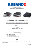
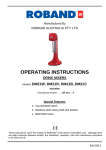
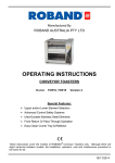
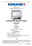
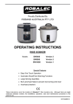
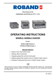
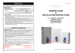
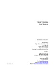
1
Proudly Distributed By ROBAND AUSTRALIA PTY LTD OPERATING INSTRUCTIONS ROBATHERM AUTOFILL BOILING WATER UNIT Models AR3, AR5, AR7, AR10, AR15,AR25, AR40 Version 1 These instructions cover the models of Robatherm Boiling Water Units listed above, Although there are slight variances between models, the installation, operation, care and maintenance procedure is the same for all. 31/10/2013 Roband® Australia is a wholly Australian owned company and has been manufacturing quality commercial catering equipment for the food service industry for more than 50 years. Roband products are engineered and manufactured to the highest standards to provide functionality, reliability and durability, and our quality products are exported world-wide. Included in the comprehensive Roband® range are Toasters, Fryers, Milkshake Mixers, Rotisseries, Food Display Cabinets and much more. Roband® Australia also acts as the Australian agents for Vitamix® Blenders, Noaw® Meat Slicers, Ryno® Stainless Benching, Ceado Juicers, Förje® Cookware, RobalecTM Soup/Rice Warmers, Robatherm Urns, Austheat® Fryers, Dipo Induction & Autofry Machines. Roband also has its own line of commercial cookware and cutlery under the Robinox® brand name. For a complete set of brochures please contact your nearest authorised dealer or contact Roband directly at our head office. Roband Head Office Sydney, Australia Roband Australia Pty Ltd 1 Inman Road Dee Why NSW 2099 AUSTRALIA Tel: +61 2 9971 1788 Fax: +61 2 9971 1336 Email: [email protected] Web: www.roband.com.au International Agents For additional agents please email Head Office Cyprus: Fiji: Hong Kong: Malaysia: Maldives: New Zealand: Noumea: Noumea: Papua New Guinea: United Catering Equipment Supplies Ph: +357 777 777 24 Hotel Equipment Ltd Ph: +679 672 0666 Chung Wah Kitchen Machine Ltd Ph: +852 2334 5411 Allied Food Equipment Ph: +603 9133 5833 Radiant Heat Maldives Pty Ltd Ph: +960 333 4845 Roband New Zealand Ph: +649 274 1354 Comptoir Materiel Professionnel Ph: +687 28 50 43 CHR Import Ph: +687 92 83 79 Brian Bell & Company Pty Ltd Ph: +675 325 5411 Singapore: Switzerland: Thailand: United Arab Emirates: United Arab Emirates: United Kingdom: USA: Jelco Private Ltd Ph: +655 611 988 Burgi Infra Grill Ph: +41 418 554 552 Seven Five Distributors Co Ltd Ph: +662 866 5858 Boncafe Middle East LLC +9714 282 8742 Nisa Trading LLC +9714 396 6132 Metcalfe Catering Equipment Ph +44 1766 830 456 Condon & Fisher International Ph: +1 508 361 9226 © Copyright 2013 – Roband® Australia Pty Ltd All rights reserved. No part of this work may be reproduced or copied in any form or by any means, electronic or mechanical, including photocopying or posting to a website, without the written permission of the publisher. The material contained within this document is intended entirely for instructional purposes. CONTENTS INTRODUCTION ..................................................................................................... 1 GENERAL PRECAUTIONS ..................................................................................... 1 PACKAGING ........................................................................................................... 2 COMPLIANCE ......................................................................................................... 2 INSTALLATION ....................................................................................................... 3 OPERATION............................................................................................................ 7 GENERAL SAFETY ............................................................................................... 12 CLEANING, CARE & MAINTENANCE .................................................................. 12 TROUBLESHOOTING ........................................................................................... 13 PRODUCT ERROR CODES.................................................................................. 14 SPECIFICATIONS ................................................................................................. 15 CIRCUIT DIAGRAM............................................................................................... 17 WARRANTY .......................................................................................................... 20 INTRODUCTION Congratulations on your purchase of this quality Robatherm product. With proper care and management your new purchase will give you years of trouble free service. By reading these instructions carefully you can ensure that this machine is used and maintained properly, helping your new investment to perform well for you now, and to continue performing in the many years to come. GENERAL PRECAUTIONS This machine must only be operated by qualified person(s) who are fully versed in the operating and safety instructions described in this manual. Operators should be instructed to familiarise themselves with any and all safety instructions described in this manual prior to commencement of any maintenance or service. In the case of new personnel, training is to be provided in advance. These machines should not be operated by persons (including children) with reduced physical, sensory or mental capabilities, or lack of experience or knowledge, unless they are being supervised or being instructed concerning the safe use of the appliance by a person responsible for their safety. The machine should be disconnected from all power and allowed to cool before cleaning. Any damaged plug or cord should be replaced before further use. These machines should not be cleaned with the use of a spray applicator, water jet or any other method except those outlined in the Cleaning & Care section of these instructions. Roband will accept no liability if; Non-authorised personnel have tampered with the machine. The instructions in this manual have not been followed correctly. Non-original spare parts are used. The machine is not cleaned correctly, with the right product. There is any damage to the unit Page: 1 PACKAGING All care is taken when packing and Roband ensures that every unit is functional and undamaged at the time of packaging. The Package of this Boiling Water Unit should include: 1. One Boiling Water Unit (appropriate model) 2. This Manual Any damage to the machine as a result of freight must be reported to the Freight Company and to the agent responsible for the despatch of said unit within 24 hours of receipt. No claims will be accepted or entertained after this period. To prevent damage during transport, the tap is packed inside the unit housing. For the AR3, AR5 and AR10 units, remove the four screws located on the top and bottom of the unit and slide the housing toward you. For AR15, AR25 and AR40 models, unscrew and remove the access panel on the left hand side of the unit. COMPLIANCE C-Tick: Robatherm products have been designed and manufactured to comply with any and all specifications set out by the Australian Communications Authority (ACA) in regards to Electromagnetic Compatibility. As testament to such compliance these units bear the C-Tick symbol. For further information contact the Australian Communications Authority, PO Box 13112, Law Courts, Melbourne VIC 8010. Page: 2 INSTALLATION Remove all the packaging materials and tape, as well as any protective plastic from the machine. Clean off any glue residue left over from the protective plastic or tape. Note: Caution is suggested if the Boiling Water Unit is to be connected to a water supply with a high content of silica or calcium. Water supplies of this nature may be detrimental to the unit’s operation and may cause the warranty to become void. For further information relating to the guidelines of water quality, contact your local Roband office for advice. This boiling water unit shall be installed by a qualified service person. The installation must comply with AS/NZS 3000 and AS/NZS 3500.4 and all relevant statutory and local body requirements of the state in which the Boiling Water Unit is installed. This boiling water unit contains electronic equipment and insulation tests must only be conducted between neutral and earth or between active and earth. LOCATION This unit is designed for interior installation only. OPENING THE UNIT To remove the cover from models AR3, AR5, AR7 & AR10 remove the 4 retaining screws at the top and bottom and pull the jacket forward. For models AR15, AR25 and AR40, unscrew the service plate on the left hand side and lid at the top. MINIMUM CLEARANCES For ventilation reasons, all units require a minimum clearance of 50mm on all sides. For ease of servicing (where there is sufficient space) we recommend 300mm clearance from the top of all units. For element replacement reasons we recommend clearance of 150mm from the right hand side of 3 to 10 litre units and 300mm from the left hand side of the 15, 25 and 40 litre units. MOUNTING The unit, when installed, is suspended from mounting screws located into keyhole slots at the back of the unit (refer to the Mounting Dimension Specification). Be sure that the mounting screws are securely inserted into the keyhole slots. The screws MUST be anchored in such a way, that they will hold the weight of the unit when filled with water, (refer to Figure 1). WARNING: Before drilling into the wall make sure that the screw positions avoid any pipe-work or electrical cables. Allow 4 mm clearance between the screw head and the wall for locating the unit. Page: 3 Model J mm K mm L mm 3L 46 189 31 5L 46 241 31 7.5 L 46 241 31 10 L 46 241 31 15 L 75 340 20 25 L 75 340 20 40 L 75 340 20 Figure 1: Mounting Dimension Specification WATER SUPPLY CONNECTION Cold mains pressure water (refer to specification table for minimum water pressures) must be piped and connected to the ½” BSP inlet fitting located on the left hand side underneath the unit. An accessible isolating valve must be installed near the unit. This unit contains an inlet strainer on the water inlet connection (refer to figure 1). To ensure continuing satisfactory operation, it is suggested that the inlet strainer be serviced every six months by a qualified service person. Where poor water quality is present it is recommended to install an additional auxiliary filter. Page: 4 Overflow / Vent Connection Figure 2: Water Connection & Overflow/Vent Connection For rear entry connection on 3-10 Litre models, we recommend that you use a braided flexible hose with a 90 elbow for ease of connection. An isolating valve should be installed in the system to enable water to the unit to be turned off in the event of any fault. OVERFLOW / VENT CONNECTION IMPORTANCE Connect a 15 mm (½”) pipe to the overflow/vent connection (½”BSP nipple). This pipe is to be made of a material such that continuous steam will not degrade it (eg copper). This pipe must have a continuous fall, not exceeding 3 metres in length and / or contain no more than 4 bends (refer to figure 2). The drain pipe work must not exert a pressure of more than 1 metre of head on the boiling unit (refer to figure 2). If the site situation requires a pipe length exceeding 3 metres, or a discharge head (vertical distance between vent outlet and inlet) greater than 1 meter, then discharge the overflow/vent into a tundish. During normal operation of the unit, the overflow/vent connection may discharge small quantities of steam and condensate, so it is ESSENTIAL that the drain pipe is attached to the overflow vent connection. This drain pipe must discharge to waste at a point where no scald injury, nuisance nor inconvenience is caused to people in the immediate vicinity. Page: 5 DRAINING THE UNIT WARNING: Before draining the unit, ensure the appliance has been switched off, and water is not hot enough to scald. To drain 3-25L models, turn unit off and open tap until no water flows out. Remove unit from wall and tip over with tap open until unit is empty. For 40L units, a drain plug is accessible from the bottom of the unit (note switch unit off before draining) TAP OUTLET To prevent damage during transport, the tap is packed inside the unit housing. For the AR3, AR5 and AR10 units, remove the four screws located on the top and bottom of the unit and slide the housing toward you. For AR15, AR25 and AR40 models, unscrew and remove the access panel on the left hand side of the unit. The tap is connected to the tap extension by a chrome-plated nut and tightened using a 29 mm AF spanner. ELECTRICAL REQUIREMENTS: WARNING: If this boiling water unit is to be installed in a newly constructed building, ensure that all electrical tests including insulation tests have been performed prior to plugging in and switching on your new Boiling Water Unit. Failure to do so could damage the electronics. 220 –240 Volts AC, 50 Hz, Single Phase 10 Amps on 3, 5, 7.5,10 & 15 litre models 15 Amps on 25 litre model 20 Amps on 40 litre model A flexible cord complete with a plug is supplied on AR3-AR15 models. Do not loosen the cord grip or pull excess cord into the water boiling unit. If the supply cord of this unit is damaged, it must be replaced by Roband or a qualified service person. The 25 and 40 litre models must be installed with fixed wiring. A means of disconnection from all active (phase) conductors of the power supply must be incorporated during installation in accordance with the wiring rules. Page: 6 OPERATION Once the installation is complete, turn the water supply on before switching on the power. The unit is programmed to automatically operate 24 hours a day, 7 days a week. It is highly recommended for the user to program the timer (if the unit supplied has one), as this will increase the life of the unit and consume less power (see below for instructions detailing how to program the timer). Note: On initial start-up the timer screen will display “CALIBRATING DO NOT INTERRUPT”. The unit automatically runs through a set-up cycle to detect the boiling point of water. This will take between 18 to 30 minutes (depending on the unit capacity) and steam will discharge from the vent pipe for a short time. Do not operate the tap during the set-up cycle because it may affect the unit operating temperature. The electronic controller constantly monitors and controls the water level and water temperature to optimise the boiling water delivery. INITIAL OPERATING INSTRUCTIONS After the unit has been installed, replace the front cover and fit the tap by wrapping a couple of turns of Teflon tape around the thread and turning tap clockwise into the socket on the front of the unit. If the tap is not completely tight, remove it and add more Teflon tape then repeat the procedure. Turn on the water and check for leaks. Turn on the power and wait twenty minutes before using. During this period the unit will function in the following sequence. The unit will first prime itself with water up to the tap level. The element will then be energised and that initial amount of water will be boiled, taking approximately 10 to 15 minutes. The unit will then start the automatic heat and fill cycle until the tank is full. The unit will then go into “maintenance mode” keeping the water at boiling point. Please note: The units are factory set and are not user serviceable. If the unit malfunctions refer to TROUBLESHOOTING for advice. If that advice fails to solve the problem, contact your distributor or our office for further help. Operation based on an inlet water temperature of 18ºC Approx. Time to Capacity Approx. Recovery heat full Capacity Litres Cups(160ml) Litres / Hour Cups (160ml) / Hour (min) 3 5 7.5 10 15 25 19 31 47 62 94 156 17.5 21 21 21 21 33 109 131 131 131 131 206 12 15 22 29 40 40 40 250 41 256 50 Page: 7 FOR UNITS WITH TIMER Timer Functions A. Clock B. Timer STD/AUTO C. Set Sleep Delay Time* D. Set ON/OFF Times* E. Filter Life i. Remaining Life ii. Filter Reset iii. Service Menu * ON/OFF times & Sleep Delay Time only operate in AUTO Mode. To select a Timer Mode Press the (Prog) button until the desired mode is displayed on the screen. Press the (Accept) button to confirm selection. Pressing (Cancel) button at any time returns the unit to the main menu. Any functions previously accepted will be retained. Note: The display will revert back to main menu from any mode if a button has not been pressed for 1 minute. A) Setting the Clock Select the clock mode (Prog>Clock>Accept) Display Shows: “Set Clock Day”. Press the (UP) button until the desired day appears on the screen and press the (Accept) button to confirm selection. Display Shows: “Set Clock HOUR” Press the (UP) button until the desired hour (24 Hour Time) appears flashing on the screen and press the (Accept) button to confirm selection. Display Shows: “Set Clock MIN” Press the (UP) button until the desired minute appears flashing on the screen. Press the (Accept) button to confirm selection and the display reverts to the main menu B) Set Timer to STD/AUTO Mode Select the Timer STD/AUTO mode (Prog>Timer STD/AUTO>Accept) Display Shows: “STD” Pressing the (UP) button alternates the “STD”/“AUTO” icons. STD operation means that the unit operates 24 hours a day, Auto mode reverts the unit to operate at the Page: 8 pre set times on the timer. Press the (Accept) button to confirm selection and the display reverts to the main menu. If the timer is in AUTO mode, pushing any Timer key will reactivate the unit. The unit will operate normally until the next programmed “Off” time. C) To Set Sleep Delay Time. Select the Sleep on/off mode (Prog>Sleep DelayTime>Accept) Display Shows: “Sleep Delay Time” “ OFF”. The sleep function puts the unit in a standby mode after user defined period. The Sleep Delay will be factory set to OFF as the default setting. Pressing the (UP) button increases the delay time up to 6 hours. Press the (Accept) button to confirm selection and the display reverts to the main menu. The unit will go into “Sleep” mode if it has not been used for the “Sleep Delay Time” period. To exit “Sleep”, push any Timer key. D) To Set ON/OFF Times Select the Timer ON/OFF mode (Prog>Set ON/OFF times>Accept) Note: to set the unit to be in off mode for an entire day, set the “on” and “off” times to be the same eg: On = 0:00 Off = 0:00 Display Shows: “SUN” “7:00 – 7:00” “Set ON hour”. Press the (UP) button until the desired hour appears on the screen and press the (Accept) button to confirm selection. Display Shows: “SUN” “7:00 – 7:00” “Set ON minute”. Press the (UP) button until the desired minute appears on the screen and press the (Accept) button to confirm selection. Display Shows: “SUN” “7:00 – 7:00” “Set OFF hour”. Press the (UP) button until the desired hour appears on the screen and press the (Accept) button to confirm selection. Display Shows: “SUN” “7:00 – 7:00” “Set OFF Minute”. Press the (UP) button until the desired minute appears on the screen and press the (Accept) button to confirm selection and advance to the next day. Display Shows: “MON” “7:30 – 15:30” “Set ON hour”. Note: Continue with same procedure for Monday through to Saturday. E) Filter Life Select the Appropriate Filter Mode Remaining Life Filter Reset Page: 9 i) To Select Remaining Life mode (Prog>Filter Life>Accept>Remaining Life) Display Shows: “Remaining Life” “XXXX litres“ Press the (Cancel) or (Accept) button to revert back to the main menu. ii) To Select the Filter Reset mode (Prog> Filter Life >Accept>filter reset>Accept) Display Shows: “Filter Reset” Press the (Accept) button to confirm selection at which time you are prompted “Are you sure?”. Press (Accept) once more reset the filter and to return to the Filter Life Menu. Display Shows: “Set Filter Life” “4000 Litres”. Pressing (UP) button scrolls to the filter OFF selection (this turns the filter count off if a filter is not installed with the boiling water unit). Press the (Accept) button to confirm selection and the display reverts to the Filter menu Filter count can be adjusted in the range of 1000 litres to 14000 litres in increments of 1000 litres F) Service Menu Select Appropriate Service Mode i. Error Codes ii. Boiling Temp iii. Chiller Temp (Not Used) iv. Calib Reset v. Software Version vi. Temp Show ON/OFF vii. TB Treq viii. Temp override ix. i) Error Codes (Prog>Service>Accept>Error Codes) This function allows easy identification of problems occurring with the unit by service technicians (see details on page 10 – Product error codes). ii) For Boiling Unit Display Temp mode (Prog>Service>Accept>Boiling Temp) Display Shows: “XXX ˚C“ This function displays the current hot water temperature. Press the (Cancel) button to revert back to the main menu. Page: 10 iii) Not Used Display Shows: “XXX ˚C“ Press the (Cancel) button to revert back to the main menu. iv) For Calibration Reset mode (Prog>Service>Accept>Calib.Reset>Accept) Display Shows: “Calib. Reset“ This function recalibrates the boiling water unit to boiling point. Press the (Accept) button to recalibrate the boiling point. Press (Accept) again at the “Are You Sure” prompt. Press the (Cancel) button to revert back to the Main menu. v) To Display the Software Version (Prog>Service>Accept>Software Version>Accept) vi) Temp Show On/Off (Prog>Service>Accept>TempShow ON/OFF) This function allows the temperature of the water within the boiling water unit to be displayed permanently on the screen. Press the (Accept) button to confirm selection and the display reverts to the main menu vii) TB Treq (Prog>Service>Accept>TB Treq) This function shows the user the temperature to which the unit is calibrated. Under the letters TB the boiling calibration temperature is displayed. The temperature displayed beneath the letters “Treq” indicates the temperature at which the unit will maintain the water. viii) Temperature override (Prog>Service>Accept>Temp Override>Accept) This function allows the serviceman to perform a fast unit calibration. Keypad Lock This function provides extra security to prevent tampering with the unit settings. Default setting is disabled. (Prog>Keypad Lock>Accept) The message “Keylock Enabled” will display on screen. Press Accept key. “Keypad locked” message will display on screen every time a timer button is pressed. To deactivate this function press Progr and Up buttons simultaneously for a period of 5 seconds. Page: 11 SAFETY GENERAL SAFETY This machine contains no user-serviceable parts. Roband Australia, one of our agents, or a similarly qualified person(s) should carry out any and all repairs. Any repair person(s) should be instructed to read the Safety warnings within this manual before commencing work on these units. Steel cutting processes such as those used in the construction of this machine result in sharp edges. Whilst any such edges are removed to the best of our ability it is always wise to take care when contacting any edge. Particular care should be taken to avoid contact with any steel edge, and warnings should be given in regards to the danger of such contact to any repair or maintenance person(s) prior to commencement of any servicing. Do not remove any cover panels that may be on the machine. This unit can get very hot. Ensure everyone is aware that the machine is operating and take care to avoid contact with hot surfaces. Always ensure the power cable is not in contact with hot parts of the machine when in use. Keep out of reach of children. Ensure that any damaged power cord is replaced before further use. CLEANING, CARE & MAINTENANCE To clean the Hot water Urn, use hot soapy water with a clean sponge or cloth to wipe the external surfaces. Caution: Although every care is taken during manufacture to remove all sharp edges, care should be taken when cleaning to avoid injury. Particular care should be taken when cleaning near the edges of the unit. Page: 12 TROUBLESHOOTING If the Boiling Water Unit does not function, check the following points before calling for service. # SYMPTOM 1. The unit does not fill with water POSSIBLE CAUSE There is no power supply There is no water supply The inlet strainer is blocked Electronic Controller failure Solenoid Valve failure The Filter is blocked (If unit is supplied with an inlet water filter) Thermal cut-out has tripped 2. The unit fills water to low level and does not heat Heating element failure Electronic Controller failure Thermistor failure Low Air Pressure 3. 4. The unit boils continuously The unit overflows Electronic Controller failure Thermistor failure Incoming water pressure is too high Solenoid valve failure Level probe failure The unit did not fill with enough water There is no water from the tap REMEDY Check the electrical supply – Check that the unit is plugged in. Check the water supply. Check the Inlet Strainer, clean or replace. Test the electronic controller. Check resistance of the solenoid, replace if broken. Check the filter, replace if blocked (see section 5E for re setting the filter) Reset the thermal cut-out. If the heating element is properly wired, then check its resistance. Replace if broken. Test the electronic controller. Replace the thermistor. Recalibrate the unit (see section 5F sub section v) for how to recalibrate the unit Test the electronic controller. Replace the thermistor. Reduce incoming water pressure. Turn the unit off. If water still overflows, replace the solenoid valve. Clean the level probe Replace the level probe See 1. & 2. above. Drain water out of the unit (see paragraph 6 on page 4). When unit is empty, disassemble and repair the tap. **It is strongly recommended that any REMEDY be carried out by a qualified service person** 5. The tap diaphragm is disconnected from its spindle NOTE: Should the unit have a fault in which the machine is leaking, turn the power off and open the tap to drain the unit. DO NOT REMOVE THE UNIT FROM THE WALL, as service will only be carried out if the unit is still mounted and connected. Page: 13 PRODUCT ERROR CODES Error Code Hot Thermistor O/C, S/C A Heating Triac S/C – uncontrolled temperature rise C Expired Filter E Calibration Time Out G Low Level Probe Fault H High Level Probe Fault J Water Heating Fault L Internal Software Reset – No action req’d. M Rapid Temperature Rise – i.e. Empty Tank N Page: 14 SPECIFICATIONS Drawing Applies To All Models Page: 15 SPECIFICATIONS continued Key to Drawing Dimensions: Dimension 3 Litre 5 Litre 7.5 Litre 10 Litre 15 Litre 25 Litre 40 Litre A mm 283 334 334 334 490 490 490 B mm 143 176 176 176 180 235 325 C mm 400 430 515 615 615 615 615 D mm 234 267 267 267 271 326 416 E mm 15 15 15 15 8 8 8 F mm 50 50 50 50 32 32 32 G mm 53 53 53 53 103 103 103 H mm 18 18 18 18 32 32 32 N mm 212 245 245 245 249 304 394 M mm 142 167 167 167 245 245 245 Table 3: Dimension Specification Specifications: Size (L) 3 5 7.5 10 15 25 40 Approx. Weight – Empty (Kg) 6 8 9 10 15 17 19 Approx. Weight – Full (Kg) 10 15 19 22 34 47 67 Min Water Pressure (kPa) 50 50 50 50 75 75 100 Max Water Pressure (kPa) 1000 1000 1000 1000 1000 1000 1000 Element Power (kW) 1.8 2.4 2.4 2.4 2.4 3.6 4.6 Page: 16 CIRCUIT DIAGRAM 3 – 15L MODELS 25 & 40L MODELS NOTE: This circuit diagram has been provided for reference and to assist qualified service and repair agents only. Under no circumstances should person’s not suitably qualified attempt repairs to any electrical equipment. Page: 17 NOTES Page: 18 NOTES Page: 19 WARRANTY Every care is taken to ensure that no defective equipment leaves our factory and all goods manufactured by us are guaranteed against faulty workmanship and materials for a period of 12 months from the date of purchase. Glass, lamps and Teflon coatings are NOT included in this warranty. Generally, all goods claimed under this warranty must be returned to the factory or an authorised service agent, freight prepaid, for inspection. Any part deemed to be defective will be replaced, however, no claims will be entertained for parts damaged in transport, misused or modified in any way without our approval. For machines that are not considered to be portable (e.g. food bars, rotisseries, large hotplates and some bain maries), on site warranty service will be provided in capital city metropolitan areas only. In all other locations, the customer is responsible for all travelling time/service call costs and payment for this will be required prior to the commencement of the repair. The labour costs to actually repair the fault will be met by this company. This company reserves the right to reject a claim for warranty if it is not completely satisfied with the circumstances under which it occurred and any costs incurred for false claims or faults due to incorrect usage etc. are the responsibility of the claimant. Under no circumstances shall Roband® Australia Pty Ltd or any subsidiary company or Agent be liable for loss of profit or damage to other equipment and property. Generally, authorised service agents are located in all areas, which have authorised distribution dealers. For the name of your nearest Australian authorised service agent please contact: ROBAND® AUSTRALIA PTY LTD Warranty Number: 1800 268 848 (for Australian Residents) Phone: +61 2 9971 1788 Fax: +61 2 9971 1336 Email: [email protected] All other countries please contact your selling agent. Please complete the following details and keep this card in a safe place. NAME ADDRESS MODEL No: SERIAL No: DATE PURCHASE NAME OF DEALER: PLEASE RETAIN THIS SECTION FOR YOUR RECORDS DO NOT POST ROBAND® AUSTRALIA PTY LTD Page: 20 OTHER LEADING PRODUCTS AVAILABLE: -PLUS PIE & FOOD WARMERS DRINK MIXERS HIGH PERFORMANCE DEEP FRYERS VITAMIX BLENDERS GRILLMAX TOASTERS NOAW Slicers Manufactured/Imported in Australia by: Authorised Distributor/Agent