1
Part No. 316937A
WARRANTY
In addition to your legal rights, Rheem makes the following promise to the owner. We will repair or, if
necessary, replace a defective boiling water unit or part of it, which has failed due to faulty manufacture on the
following terms and conditions:
WARRANTY PERIOD
AGE OF BOILING WATER UNIT
FROM THE DATE OF INSTALLATION
Up to (1) year
WARRANTY COVERS ALL BOILING WATER UNITS DOMESTIC,
COMMERCIAL OR INDUSTRIAL
Free replacement of failed component, or if necessary, replacement of
the Boiling Water Unit, free of charge, including labour.**
** Refer to item 3, Warranty Conditions.
Should your boiling water unit need service under warranty, please call RHEEM SERVICE on
131 031 or refer to the yellow pages under Water Heaters for your nearest local service agent.
WARRANTY CONDITIONS:
1.The Boiling Water Unit must be installed in accordance with the installation instructions, supplied with the
Boiling Water Unit, and in accordance with all relevant statutory and local requirements of the state in which
the Boiling Water Unit is installed.
2.Where a failed component or Boiling Water Unit is replaced under Warranty, the balance of the original Warranty
Period will remain effective. The replaced part or Boiling Water Unit does not carry a new Warranty.
3.Where the Boiling Water Unit is installed outside the boundaries of a metropolitan area as defined by
Rheem, or beyond 25 km from a regional Rheem branch office, or a Rheem Authorised Service Centre, the
cost of transport, insurance and travelling costs between the nearest Rheem Authorised Service Centre’s
premises and the installed site will be for the account of the owner.
4.The Warranty only applies to the Boiling Water Unit and therefore does not cover any plumbing or electrical
parts supplied by the installer and not an integral part of the Boiling Water Unit, e.g. pressure limiting valve,
stop cock, electrical switches, pumps or fuses.
OWNERS GUIDE
&
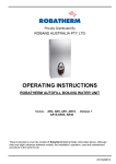
INSTALLATION INSTRUCTIONS
CLASSIC SERIES
POWDER COATED
Models 3, 5, 7.5, 10, 15, 25, & 40 Litre
STAINLESS STEEL
Models 7.5, 10, 15, 25, & 40 Litre
WARRANTY INFORMATION
WARRANTY EXCLUSIONS:
REPAIR AND REPLACEMENT WORK WILL BE CARRIED OUT AS PER THE RHEEM WARRANTY (ABOVE),
HOWEVER THE FOLLOWING EXCLUSIONS MAY CAUSE THE BOILING WATER UNIT WARRANTY TO
BECOME VOID, AND MAY INCUR A CHARGE FOR SERVICE AND COST OF REPLACED PARTS.
1. Accidental damage; Acts of God; failure due to misuse; incorrect installation, attempts to repair the unit other
than by a Rheem Authorised Service Agent, or the Rheem Service Department.
2. Where it is found that there is nothing wrong with the boiling water unit; where the complaint is related to low
or high water pressure; where there is no flow of hot water due to faulty plumbing or a blocked filter; where
water leaks are related to plumbing work and not the boiling water unit or its components, where there is a
failure of electricity or water supplies.
3. Where the boiling water unit or its component has failed directly or indirectly as a result of high water
pressure.
4. Where the boiling water unit is located in a position that does not comply with the Rheem installation
instructions or relevant statutory requirements causing the need for major dismantling or removal of
cupboards.
5. Subject to any statutory provisions to the contrary claims for damage to furniture, carpets, walls, foundations,
or any other consequential loss either directly or indirectly due to leakage from a boiling water unit.
6. Repairs to the boiling water unit due to scale formation in the waterways when the heater has been
connected to a harmful water supply as outlined in the owners guide.
Contact details:
RHEEM AUSTRALIA PTY LTD
FOR SERVICE TELEPHONE
A.B.N. 21 098 823 511
131 031
www.rheem.com.au
or refer local Yellow Pages
IMPORTANT, PLEASE LEAVE WITH THE OWNER
12.
CONTENTS
NOTES:
1. WARNING .....................................................................................................3
2. WATER QUALITY .........................................................................................3
3. INSTALLATION .............................................................................................3
A. Location .................................................................................................3
B. Opening the Unit ....................................................................................3
C. Minimum Clearance ...............................................................................3
D. Mounting ................................................................................................3
E. Water Supply Connection ......................................................................3
F. Overflow / Vent Connection Importance .................................................4
G. Drain Connection ...................................................................................4
H. Tap Outlet ..............................................................................................5
J. Electrical Requirements ..........................................................................5
4. OPERATION .................................................................................................5
MOUNTING DIMENSION SPECIFICATION FOR ALL MODELS – drawing .....6
DIMENSION SPECIFICATION FOR ALL MODELS – drawing .........................7
5. FOR UNITS WITH A TIMER ..........................................................................8
A. Setting The Clock....................................................................................8
B. Setting the Timer to STD/Auto Mode ......................................................8
C. Setting Sleep Delay Times......................................................................8
D. Setting On/Off Times ..............................................................................8
E. Filter Life .................................................................................................9
F. Service Menu ..........................................................................................9
FAULT FINDING GUIDE ..................................................................................10
NOTES .............................................................................................................11
WARRANTY INFORMATION ...........................................................................12
2.
11.
LAZER BOILING WATER UNIT: FAULT FINDING GUIDE.
LAZER BOILING WATER UNIT
INSTALLATION AND OWNERS GUIDE
**It is strongly recommended that any REMEDY be carried out by a qualified service person**
SYMPTOMS
The unit does not fill with
1. water
POSSIBLE CAUSE
There is no power supply
There is no water supply
The inlet strainer is
blocked
Electronic Controller
failure
Solenoid Valve failure
The Filter is blocked (If
unit is supplied with an
inlet water filter)
The unit fills water to low
2. level and does not heat
Test the electronic controller.
1.
Check resistance of the solenoid,
replace if broken.
Check the filter, replace if blocked
(see section 5E for re setting the
filter)
This Lazer unit produces boiling water
(third degree burns may occur) and care
should be taken at all times when using
it. This unit is not intended for use by
infirm persons and young children
should be supervised to ensure that
they do not play with the unit.
Thermal cut-out has
tripped
Reset the thermal cut-out.
Heating element failure
If the heating element is properly
wired, then check its resistance.
Replace if broken.
Electronic Controller
failure
Thermistor failure
Low Air Pressure
The unit boils
3. continuously
Check the electrical supply.
Check the water supply.
Check the Inlet Strainer, clean or
replace.
Thank you for choosing our Lazer
Boiling Water Unit. Please take a few
minutes to read this booklet because it
contains important information about
the correct installation and operation of
your Lazer unit.
REMEDY
Electronic Controller
failure
Thermistor failure
Test the electronic controller.
Replace the thermistor.
Recalibrate the unit (see section 5F
sub section v) for how to recalibrate
the unit
Test the electronic controller.
Replace the thermistor.
WARNING:
2. WATER QUALITY
Caution is suggested if the Boiling
Water Unit is to be connected to a water
supply with a high content of silica or
calcium. Water supplies of this nature
may be detrimental to the unit’s
operation and may cause the warranty
to become void. For further information
relating to the guidelines of water
quality, contact your local Rheem office
for advice.
3. INSTALLATION
Incoming water pressure
is too high
4. The unit overflows
Solenoid valve failure
Level probe failure
There is no water from
5. the tap
10.
Reduce incoming water pressure.
Turn the unit off. If water still
overflows, replace the solenoid valve.
Clean the level probe
Replace the level probe
The unit did not fill with
enough water
See 1. & 2. above.
The tap diaphragm is
disconnected from its
spindle
Drain water out of the unit
(see paragraph 6 on page 4).
When unit is empty, disassemble and
repair the tap.
This boiling water unit shall be installed
by a qualified service person. The
installation must comply with AS/NZS
3500.4 and all relevant statutory and
local body requirements of the state in
which the Boiling Water Unit is installed.
A. LOCATION
This unit is designed
installation only.
for
interior
B. OPENING THE UNIT
To remove the jacket from models 3, 5,
7.5 & 10 L remove the 4 retaining
screws at the top and bottom and pull
the jacket forward. For models 15, 25
and 40 L unscrew the lid at the top and
service plate on the left hand side.
C. MINIMUM CLEARANCES
For ventilation reasons, all units require a
minimum clearance of 50mm on all sides.
For ease of servicing (where there is
sufficient space) we recommend 300mm
clearance from the top of all units. For
element
replacement
reasons
we
recommend clearance of 150mm from the
right hand side of 3 to 10 litre units and
300mm from the left hand side of the 15 to
40 litre units.
D. MOUNTING
The Lazer when installed is suspended
from mounting screws located into keyhole
slots
at
the
back
of
the
unit
(refer to the Mounting Dimension
Specification on page 6).
Be sure that the mounting screws are
securely inserted into the keyhole slots.
The screws MUST be anchored in such a
way, that they will hold the weight of the
unit when filled with water, (refer to the
specification table on page 5).
WARNING:
Before drilling into the wall make sure that
the screw positions avoid any pipe-work or
electrical cables. Allow 4 mm clearance
between the screw head and the wall for
locating the unit.
E. WATER SUPPLY CONNECTION
Cold mains pressure water (refer to
specification table on page 5 for minimum
water pressures) must be piped and
connected to the ½” BSP inlet fitting
located on the left hand side underneath
the unit. An accessible isolating valve must
be installed near the unit.
This unit contains an inlet strainer on the
water inlet connection (refer to figure 1). To
ensure continuing satisfactory operation, it
is suggested that the inlet strainer be
serviced every six months by a qualified
service person. Where poor water quality is
present it is recommended to install an
additional auxiliary filter.
3.
For rear entry connection on 3-10 Litre
models, we recommend that you use a
braided flexible hose with a 90° elbow
for ease of connection.
F. OVERFLOW / VENT
CONNECTION IMPORTANCE
Connect a 15 mm (½”) pipe to the
overflow/vent
connection
(½”BSP
nipple). This pipe is to be made of a
material such that continuous steam will
not degrade it (i.e. copper). This pipe
must have a continuous fall, not
exceeding 3 metres in length and / or
contain no more than 4 bends (refer to
figure 2).
If the site situation requires a pipe length
exceeding 3 metres, then discharge the
overflow/drain into a tundish.
The drain pipe work must not exert a
pressure of more than 1 metre of head on
the Lazer boiling unit (refer to figure 2).
During normal operation of the Lazer, the
overflow/vent connection may discharge
small quantities of steam and condensate,
so it is ESSENTIAL that the drain pipe is
attached to the overflow vent connection.
This drain pipe must discharge to waste at
a point where no scald injury, nuisance nor
inconvenience is caused to people in the
immediate vicinity.
WARNINGS:
Ensure the overflow/vent line remains open
because the Lazer’s tank is not designed to
be pressurised. Where freezing may occur,
protect the pipes and install an air break. It
is recommended to install an air break in
the overflow/vent drain line, no more than
300 mm from the Lazer unit. Also it is
important to connect the overflow/vent and
water inlet correctly. Incorrect connection of
pipe work may damage the unit.
G. DRAIN
Figure 1: Water Connection
WARNING:
Before draining the unit, ensure the
appliance has been switched off,
and water is not hot enough to
scald.
To drain 3-10L models, turn unit off and
open tap until no water flows out. Remove
unit from wall and tip over with tap open
until unit is empty. For 15-40L units. A drain
plug is accessible from the bottom of the
unit (note switch unit off before draining)
IMPORTANT
Installation and maintenance of the Lazer Boiling Water
unit shall be carried out by a qualified service person.
Your closest Rheem Service Centre can be contacted by
telephoning 131 031
4.
Display Shows: “SUN” “7:00 – 7:00”
“Set OFF hour”.
Press the (UP) button until the desired
hour appears on the screen and press
the (Accept) button to confirm
selection.
Display Shows: “SUN” “7:00 – 7:00”
“Set OFF Minute”.
Press the (UP) button until the desired
minute appears on the screen and
press the (Accept) button to confirm
selection and advance to the next day.
Display Shows: “MON” “7:30 – 15:30”
“Set ON hour”.
Note: Continue with same procedure for
Monday through to Saturday.
E) Filter Life
Select the Appropriate Filter Mode
i. Remaining Life
ii. Filter Reset
iii. Filter Life
i) To Select Remaining Life mode
(Prog>Filter Life>Accept>Remaining
Life)
Display Shows: “Remaining Life”
“XXXX litres“
Press the (Cancel) or (Accept) button
to revert back to the main menu.
ii) To Select the Filter Reset mode
(Prog> Filter Life >Accept>filter
reset>Accept)
Display Shows: “Filter Reset”
Press the (Accept) button to confirm
selection at which time you are
prompted “Are you sure?”. Press
(Accept) once more reset the filter and
to return to the Filter Life Menu.
iii) To Select the Filter Life mode
(Prog> Filter Life >Accept>Set Filter
Life>Accept)
Display Shows: “Set Filter Life”
“5000 Litres”.
Pressing the (UP) button increases the
5000 litres value in increments of 500
litres to a maximum value of 12000
litres. Press the (Accept) button to
confirm selection and the display reverts
to the Filter menu.
F) To Service Menu
Select Appropriate Service Mode
i. Error Codes
ii. Boiling Temp
iii. Chiller Temp
iv. Calib Reset
v. Software Version
vi. Temp Show ON/OFF
i) Product Error Codes
(Prog>Service>Accept>Error Codes)
This function allows easy identification of
problems occurring with the unit by service
technicians.
ii) For Boiling Unit Display Temp mode
(Prog>Service>Accept>Boiling Temp)
Display Shows: “XXX ˚C“
This function displays the current hot water
temperature.
Press the (Cancel) button to revert back to
the main menu.
iii) For Chiller Unit Display Temp Mode
(NOT USED ON LAZER PRODUCTS)
(Prog>Service>Accept>Chiller Temp)
Display Shows: “XXX ˚C“
Press the (Cancel) button to revert back to
the main menu.
iv) For Calibration Reset mode
(Prog>Service>Accept>Calib.Reset>Accept)
Display Shows: “Calib. Reset“
This function recalibrates the boiling water
unit to boiling point. Press the (Accept)
button to recalibrate the boiling point. Press
(Accept) again at the “Are You Sure”
prompt. Press the (Cancel) button to revert
back to the Main menu.
v) To Display the Software Version
(Prog>Service>Accept>Software
Version>Accept)
vi) Temp Show On/Off
(Prog>Service>Accept>TempShow
ON/OFF)
This function allows the temperature of the
water within the boiling water unit to be
displayed permanently on the screen.
Press the (Accept) button to confirm
selection and the display reverts to the
main menu.
9.
5. For Units With a Timer
B) Set Timer to STD/AUTO Mode
Timer Functions
Select the Timer STD/AUTO mode
(Prog>Timer STD/AUTO>Accept)
Display Shows: “STD”
Pressing the (UP) button alternates the
“STD”/“AUTO” icons. STD operation means
that the unit operates 24 hours a day, Auto
mode reverts the unit to operate at the pre
set times on the timer. Press the (Accept)
button to confirm selection and the display
reverts to the main menu. If the timer is in
AUTO mode, pushing any Timer key will
reactivate the unit. The unit will operate
normally until the next programmed “Off”
time.
A.
B.
C.
D.
E.
i.
ii.
iii.
F.
Clock
Timer STD/AUTO
Set Sleep Delay Time*
Set ON/OFF Times*
Filter Life
Remaining Life
Filter Reset
Filter Life
Service Menu
* ON/OFF times & Sleep Delay Time
only operate in AUTO Mode.
To select a Timer Mode
Press the (Prog) button until the desired
mode is displayed on the screen. Press
the (Accept) button to confirm
selection. Pressing (Cancel) button at
any time returns the unit to the main
menu.
Any
functions
previously
accepted will be retained.
Note: The display will revert back to
main menu from any mode if a button
has not been pressed for 1 minute.
A) Setting the Clock
Select the clock mode
(Prog>Clock>Accept)
Display Shows: “Set Clock Day”.
Press the (UP) button until the desired
day appears on the screen and press
the (Accept) button to confirm
selection.
Display Shows: “Set Clock HOUR”
Press the (UP) button until the desired
hour (24 Hour Time) appears flashing
on the screen and press the (Accept)
button to confirm selection.
Display Shows: “Set Clock MIN”
Press the (UP) button until the desired
minute appears flashing on the screen.
Press the (Accept) button to confirm
selection and the display reverts to the
main menu.
8.
C) To Set Sleep Delay Time.
Select the Sleep on/off mode (Prog>Sleep
DelayTime>Accept)
Display Shows: “Sleep DelayTime”
“ OFF”.
The sleep function puts the unit in a
standby mode after user defined period.
The Sleep Delay will be factory set to OFF
as the default setting. Pressing the (UP)
button increases the delay time up to 6
hours. Press the (Accept) button to confirm
selection and the display reverts to the
main menu. The unit will go into “Sleep”
mode if it has not been used for the “Sleep
Delay Time” period. To exit “Sleep”, push
any Timer key.
D) To Set ON/OFF Times
Select the Timer ON/OFF mode
(Prog>Set ON/OFF times>Accept)
Note: to set the unit to be in off mode for an
entire day, set the “on” and “off” times to be
the same eg: On = 0:00 Off = 0:00
Display Shows: “SUN” “7:00 – 7:00”
“Set ON hour”.
Press the (UP) button until the desired hour
appears on the screen and press the
(Accept) button to confirm selection.
Display Shows: “SUN” “7:00 – 7:00”
“Set ON minute”.
Press the (UP) button until the desired
minute appears on the screen and press
the (Accept) button to confirm selection.
H. TAP OUTLET
4. OPERATION
To prevent damage during transport the
tap is wrapped and placed inside the
carton.
The tap is connected to the tap extension
by a chrome-plated nut and tightened
using a 29 mm AF spanner.
When the installation is complete, first turn on
the water supply before switching on the
power. The unit is programmed to
automatically operate 24 hours a day, 7 days
a week. It is highly recommended for the user
to program the timer (if the unit supplied has
one), as this will increase the life of the unit,
and consume less power (see Section 5 for
how to program the timer).
The electronic controller constantly monitors
and controls the water level and water
temperature to optimise the boiling wate
delivery.
J. ELECTRICAL REQUIREMENTS:
WARNING:
If this boiling water unit is to be installed
in a newly constructed building, ensure
that all electrical tests including
insulation tests have been performed
prior to plugging in and switching on
your new Boiling Water Unit. Failure to
do so could damage the electronics.
Operation based on an inlet water
temperature of 18ºC
• 220 –240 Volts AC, 50 Hz, Single Phase
• 10 Amps on 3, 5, 7.5,10 & 15 litre models
• 15 Amps on 25 litre model
• 20 Amps on 40 litre model
Approx Recovery
Litres / Hour
Approx. Time to heat
full Capacity
(in minutes)
3.0 L
17.5
12
5.0 L
21
15
7.5 L
21
22
10 L
21
29
15 L
21
40
25 L
33
40
40 L
41
50
Lazer
Size
A flexible cord complete with a plug is
supplied on all 3, 5, 7.5, 10 and 15 Litre
models. Do not loosen the cord grip or
pull excess cord into the Lazer. If the
supply cord of this unit is damaged, it
must be replaced by the manufacturer or
a qualified service person.
The 25 and 40 litre models must be
installed with fixed wiring. A means of
disconnection from all active (phase)
conductors of the power supply must be
incorporated
during
installation
in
accordance with the wiring rules.
SPECIFICATION
3 Litre
5 Litre
7.5 Litre
10 Litre
15 Litre
25 Litre 40 Litre
Classic Series
Approx Weight (kg) Empty
6
8
9
10
15
17
19
Approx Weight (kg) Full
10
15
19
22
34
47
67
Minimum Water Pressure kPa
50
50
50
50
75
75
100
Maximum Water Pressure kPa
1000
1000
1000
1000
1000
1000
1000
1.8
2.4
2.4
2.4
2.4
3.6
4.6
Element Size kW
5.
DIMENSION SPECIFICATION
Classic models
Figure 2: Overflow / Vent Connection
MOUNTING DIMENSION SPECIFICATION
All models
Figure 4: Dimension Specification
Figure 3: Mounting Dimension Specifications
Classic Models
6.
Dimension
3 Litre
5 Litre
7.5 Litre
10 Litre
15 Litre
25 Litre
40 Litre
J mm
46
46
46
46
75
75
75
K mm
189
241
241
241
340
340
340
L mm
31
31
31
31
20
20
20
Dimension
A mm
B mm
C mm
D mm
E mm
F mm
G mm
H mm
N mm
M mm
3 Litre
5 Litre
283
143
400
234
15
50
53
18
212
142
334
176
430
267
15
50
53
18
245
167
7.5 Litre 10 Litre
334
176
515
267
15
50
53
18
245
167
334
176
615
267
15
50
53
18
245
167
15 Litre
25 Litre
40 Litre
490
180
615
271
8
32
103
32
249
245
490
235
615
326
8
32
103
32
304
245
490
325
615
416
8
32
103
32
394
245
7.
DIMENSION SPECIFICATION
Classic models
Figure 2: Overflow / Vent Connection
MOUNTING DIMENSION SPECIFICATION
All models
Figure 4: Dimension Specification
Figure 3: Mounting Dimension Specifications
Classic Models
6.
Dimension
3 Litre
5 Litre
7.5 Litre
10 Litre
15 Litre
25 Litre
40 Litre
J mm
46
46
46
46
75
75
75
K mm
189
241
241
241
340
340
340
L mm
31
31
31
31
20
20
20
Dimension
A mm
B mm
C mm
D mm
E mm
F mm
G mm
H mm
N mm
M mm
3 Litre
5 Litre
283
143
400
234
15
50
53
18
212
142
334
176
430
267
15
50
53
18
245
167
7.5 Litre 10 Litre
334
176
515
267
15
50
53
18
245
167
334
176
615
267
15
50
53
18
245
167
15 Litre
25 Litre
40 Litre
490
180
615
271
8
32
103
32
249
245
490
235
615
326
8
32
103
32
304
245
490
325
615
416
8
32
103
32
394
245
7.
5. For Units With a Timer
B) Set Timer to STD/AUTO Mode
Timer Functions
Select the Timer STD/AUTO mode
(Prog>Timer STD/AUTO>Accept)
Display Shows: “STD”
Pressing the (UP) button alternates the
“STD”/“AUTO” icons. STD operation means
that the unit operates 24 hours a day, Auto
mode reverts the unit to operate at the pre
set times on the timer. Press the (Accept)
button to confirm selection and the display
reverts to the main menu. If the timer is in
AUTO mode, pushing any Timer key will
reactivate the unit. The unit will operate
normally until the next programmed “Off”
time.
A.
B.
C.
D.
E.
i.
ii.
iii.
F.
Clock
Timer STD/AUTO
Set Sleep Delay Time*
Set ON/OFF Times*
Filter Life
Remaining Life
Filter Reset
Filter Life
Service Menu
* ON/OFF times & Sleep Delay Time
only operate in AUTO Mode.
To select a Timer Mode
Press the (Prog) button until the desired
mode is displayed on the screen. Press
the (Accept) button to confirm
selection. Pressing (Cancel) button at
any time returns the unit to the main
menu.
Any
functions
previously
accepted will be retained.
Note: The display will revert back to
main menu from any mode if a button
has not been pressed for 1 minute.
A) Setting the Clock
Select the clock mode
(Prog>Clock>Accept)
Display Shows: “Set Clock Day”.
Press the (UP) button until the desired
day appears on the screen and press
the (Accept) button to confirm
selection.
Display Shows: “Set Clock HOUR”
Press the (UP) button until the desired
hour (24 Hour Time) appears flashing
on the screen and press the (Accept)
button to confirm selection.
Display Shows: “Set Clock MIN”
Press the (UP) button until the desired
minute appears flashing on the screen.
Press the (Accept) button to confirm
selection and the display reverts to the
main menu.
8.
C) To Set Sleep Delay Time.
Select the Sleep on/off mode (Prog>Sleep
DelayTime>Accept)
Display Shows: “Sleep DelayTime”
“ OFF”.
The sleep function puts the unit in a
standby mode after user defined period.
The Sleep Delay will be factory set to OFF
as the default setting. Pressing the (UP)
button increases the delay time up to 6
hours. Press the (Accept) button to confirm
selection and the display reverts to the
main menu. The unit will go into “Sleep”
mode if it has not been used for the “Sleep
Delay Time” period. To exit “Sleep”, push
any Timer key.
D) To Set ON/OFF Times
Select the Timer ON/OFF mode
(Prog>Set ON/OFF times>Accept)
Note: to set the unit to be in off mode for an
entire day, set the “on” and “off” times to be
the same eg: On = 0:00 Off = 0:00
Display Shows: “SUN” “7:00 – 7:00”
“Set ON hour”.
Press the (UP) button until the desired hour
appears on the screen and press the
(Accept) button to confirm selection.
Display Shows: “SUN” “7:00 – 7:00”
“Set ON minute”.
Press the (UP) button until the desired
minute appears on the screen and press
the (Accept) button to confirm selection.
H. TAP OUTLET
4. OPERATION
To prevent damage during transport the
tap is wrapped and placed inside the
carton.
The tap is connected to the tap extension
by a chrome-plated nut and tightened
using a 29 mm AF spanner.
When the installation is complete, first turn on
the water supply before switching on the
power. The unit is programmed to
automatically operate 24 hours a day, 7 days
a week. It is highly recommended for the user
to program the timer (if the unit supplied has
one), as this will increase the life of the unit,
and consume less power (see Section 5 for
how to program the timer).
The electronic controller constantly monitors
and controls the water level and water
temperature to optimise the boiling wate
delivery.
J. ELECTRICAL REQUIREMENTS:
WARNING:
If this boiling water unit is to be installed
in a newly constructed building, ensure
that all electrical tests including
insulation tests have been performed
prior to plugging in and switching on
your new Boiling Water Unit. Failure to
do so could damage the electronics.
Operation based on an inlet water
temperature of 18ºC
• 220 –240 Volts AC, 50 Hz, Single Phase
• 10 Amps on 3, 5, 7.5,10 & 15 litre models
• 15 Amps on 25 litre model
• 20 Amps on 40 litre model
Approx Recovery
Litres / Hour
Approx. Time to heat
full Capacity
(in minutes)
3.0 L
17.5
12
5.0 L
21
15
7.5 L
21
22
10 L
21
29
15 L
21
40
25 L
33
40
40 L
41
50
Lazer
Size
A flexible cord complete with a plug is
supplied on all 3, 5, 7.5, 10 and 15 Litre
models. Do not loosen the cord grip or
pull excess cord into the Lazer. If the
supply cord of this unit is damaged, it
must be replaced by the manufacturer or
a qualified service person.
The 25 and 40 litre models must be
installed with fixed wiring. A means of
disconnection from all active (phase)
conductors of the power supply must be
incorporated
during
installation
in
accordance with the wiring rules.
SPECIFICATION
3 Litre
5 Litre
7.5 Litre
10 Litre
15 Litre
25 Litre 40 Litre
Classic Series
Approx Weight (kg) Empty
6
8
9
10
15
17
19
Approx Weight (kg) Full
10
15
19
22
34
47
67
Minimum Water Pressure kPa
50
50
50
50
75
75
100
Maximum Water Pressure kPa
1000
1000
1000
1000
1000
1000
1000
1.8
2.4
2.4
2.4
2.4
3.6
4.6
Element Size kW
5.
For rear entry connection on 3-10 Litre
models, we recommend that you use a
braided flexible hose with a 90° elbow
for ease of connection.
F. OVERFLOW / VENT
CONNECTION IMPORTANCE
Connect a 15 mm (½”) pipe to the
overflow/vent
connection
(½”BSP
nipple). This pipe is to be made of a
material such that continuous steam will
not degrade it (i.e. copper). This pipe
must have a continuous fall, not
exceeding 3 metres in length and / or
contain no more than 4 bends (refer to
figure 2).
If the site situation requires a pipe length
exceeding 3 metres, then discharge the
overflow/drain into a tundish.
The drain pipe work must not exert a
pressure of more than 1 metre of head on
the Lazer boiling unit (refer to figure 2).
During normal operation of the Lazer, the
overflow/vent connection may discharge
small quantities of steam and condensate,
so it is ESSENTIAL that the drain pipe is
attached to the overflow vent connection.
This drain pipe must discharge to waste at
a point where no scald injury, nuisance nor
inconvenience is caused to people in the
immediate vicinity.
WARNINGS:
Ensure the overflow/vent line remains open
because the Lazer’s tank is not designed to
be pressurised. Where freezing may occur,
protect the pipes and install an air break. It
is recommended to install an air break in
the overflow/vent drain line, no more than
300 mm from the Lazer unit. Also it is
important to connect the overflow/vent and
water inlet correctly. Incorrect connection of
pipe work may damage the unit.
G. DRAIN
Figure 1: Water Connection
WARNING:
Before draining the unit, ensure the
appliance has been switched off,
and water is not hot enough to
scald.
To drain 3-10L models, turn unit off and
open tap until no water flows out. Remove
unit from wall and tip over with tap open
until unit is empty. For 15-40L units. A drain
plug is accessible from the bottom of the
unit (note switch unit off before draining)
IMPORTANT
Installation and maintenance of the Lazer Boiling Water
unit shall be carried out by a qualified service person.
Your closest Rheem Service Centre can be contacted by
telephoning 131 031
4.
Display Shows: “SUN” “7:00 – 7:00”
“Set OFF hour”.
Press the (UP) button until the desired
hour appears on the screen and press
the (Accept) button to confirm
selection.
Display Shows: “SUN” “7:00 – 7:00”
“Set OFF Minute”.
Press the (UP) button until the desired
minute appears on the screen and
press the (Accept) button to confirm
selection and advance to the next day.
Display Shows: “MON” “7:30 – 15:30”
“Set ON hour”.
Note: Continue with same procedure for
Monday through to Saturday.
E) Filter Life
Select the Appropriate Filter Mode
i. Remaining Life
ii. Filter Reset
iii. Filter Life
i) To Select Remaining Life mode
(Prog>Filter Life>Accept>Remaining
Life)
Display Shows: “Remaining Life”
“XXXX litres“
Press the (Cancel) or (Accept) button
to revert back to the main menu.
ii) To Select the Filter Reset mode
(Prog> Filter Life >Accept>filter
reset>Accept)
Display Shows: “Filter Reset”
Press the (Accept) button to confirm
selection at which time you are
prompted “Are you sure?”. Press
(Accept) once more reset the filter and
to return to the Filter Life Menu.
iii) To Select the Filter Life mode
(Prog> Filter Life >Accept>Set Filter
Life>Accept)
Display Shows: “Set Filter Life”
“5000 Litres”.
Pressing the (UP) button increases the
5000 litres value in increments of 500
litres to a maximum value of 12000
litres. Press the (Accept) button to
confirm selection and the display reverts
to the Filter menu.
F) To Service Menu
Select Appropriate Service Mode
i. Error Codes
ii. Boiling Temp
iii. Chiller Temp
iv. Calib Reset
v. Software Version
vi. Temp Show ON/OFF
i) Product Error Codes
(Prog>Service>Accept>Error Codes)
This function allows easy identification of
problems occurring with the unit by service
technicians.
ii) For Boiling Unit Display Temp mode
(Prog>Service>Accept>Boiling Temp)
Display Shows: “XXX ˚C“
This function displays the current hot water
temperature.
Press the (Cancel) button to revert back to
the main menu.
iii) For Chiller Unit Display Temp Mode
(NOT USED ON LAZER PRODUCTS)
(Prog>Service>Accept>Chiller Temp)
Display Shows: “XXX ˚C“
Press the (Cancel) button to revert back to
the main menu.
iv) For Calibration Reset mode
(Prog>Service>Accept>Calib.Reset>Accept)
Display Shows: “Calib. Reset“
This function recalibrates the boiling water
unit to boiling point. Press the (Accept)
button to recalibrate the boiling point. Press
(Accept) again at the “Are You Sure”
prompt. Press the (Cancel) button to revert
back to the Main menu.
v) To Display the Software Version
(Prog>Service>Accept>Software
Version>Accept)
vi) Temp Show On/Off
(Prog>Service>Accept>TempShow
ON/OFF)
This function allows the temperature of the
water within the boiling water unit to be
displayed permanently on the screen.
Press the (Accept) button to confirm
selection and the display reverts to the
main menu.
9.
LAZER BOILING WATER UNIT: FAULT FINDING GUIDE.
LAZER BOILING WATER UNIT
INSTALLATION AND OWNERS GUIDE
**It is strongly recommended that any REMEDY be carried out by a qualified service person**
SYMPTOMS
The unit does not fill with
1. water
POSSIBLE CAUSE
There is no power supply
There is no water supply
The inlet strainer is
blocked
Electronic Controller
failure
Solenoid Valve failure
The Filter is blocked (If
unit is supplied with an
inlet water filter)
The unit fills water to low
2. level and does not heat
Test the electronic controller.
1.
Check resistance of the solenoid,
replace if broken.
Check the filter, replace if blocked
(see section 5E for re setting the
filter)
This Lazer unit produces boiling water
(third degree burns may occur) and care
should be taken at all times when using
it. This unit is not intended for use by
infirm persons and young children
should be supervised to ensure that
they do not play with the unit.
Thermal cut-out has
tripped
Reset the thermal cut-out.
Heating element failure
If the heating element is properly
wired, then check its resistance.
Replace if broken.
Electronic Controller
failure
Thermistor failure
Low Air Pressure
The unit boils
3. continuously
Check the electrical supply.
Check the water supply.
Check the Inlet Strainer, clean or
replace.
Thank you for choosing our Lazer
Boiling Water Unit. Please take a few
minutes to read this booklet because it
contains important information about
the correct installation and operation of
your Lazer unit.
REMEDY
Electronic Controller
failure
Thermistor failure
Test the electronic controller.
Replace the thermistor.
Recalibrate the unit (see section 5F
sub section v) for how to recalibrate
the unit
Test the electronic controller.
Replace the thermistor.
WARNING:
2. WATER QUALITY
Caution is suggested if the Boiling
Water Unit is to be connected to a water
supply with a high content of silica or
calcium. Water supplies of this nature
may be detrimental to the unit’s
operation and may cause the warranty
to become void. For further information
relating to the guidelines of water
quality, contact your local Rheem office
for advice.
3. INSTALLATION
Incoming water pressure
is too high
4. The unit overflows
Solenoid valve failure
Level probe failure
There is no water from
5. the tap
10.
Reduce incoming water pressure.
Turn the unit off. If water still
overflows, replace the solenoid valve.
Clean the level probe
Replace the level probe
The unit did not fill with
enough water
See 1. & 2. above.
The tap diaphragm is
disconnected from its
spindle
Drain water out of the unit
(see paragraph 6 on page 4).
When unit is empty, disassemble and
repair the tap.
This boiling water unit shall be installed
by a qualified service person. The
installation must comply with AS/NZS
3500.4 and all relevant statutory and
local body requirements of the state in
which the Boiling Water Unit is installed.
A. LOCATION
This unit is designed
installation only.
for
interior
B. OPENING THE UNIT
To remove the jacket from models 3, 5,
7.5 & 10 L remove the 4 retaining
screws at the top and bottom and pull
the jacket forward. For models 15, 25
and 40 L unscrew the lid at the top and
service plate on the left hand side.
C. MINIMUM CLEARANCES
For ventilation reasons, all units require a
minimum clearance of 50mm on all sides.
For ease of servicing (where there is
sufficient space) we recommend 300mm
clearance from the top of all units. For
element
replacement
reasons
we
recommend clearance of 150mm from the
right hand side of 3 to 10 litre units and
300mm from the left hand side of the 15 to
40 litre units.
D. MOUNTING
The Lazer when installed is suspended
from mounting screws located into keyhole
slots
at
the
back
of
the
unit
(refer to the Mounting Dimension
Specification on page 6).
Be sure that the mounting screws are
securely inserted into the keyhole slots.
The screws MUST be anchored in such a
way, that they will hold the weight of the
unit when filled with water, (refer to the
specification table on page 5).
WARNING:
Before drilling into the wall make sure that
the screw positions avoid any pipe-work or
electrical cables. Allow 4 mm clearance
between the screw head and the wall for
locating the unit.
E. WATER SUPPLY CONNECTION
Cold mains pressure water (refer to
specification table on page 5 for minimum
water pressures) must be piped and
connected to the ½” BSP inlet fitting
located on the left hand side underneath
the unit. An accessible isolating valve must
be installed near the unit.
This unit contains an inlet strainer on the
water inlet connection (refer to figure 1). To
ensure continuing satisfactory operation, it
is suggested that the inlet strainer be
serviced every six months by a qualified
service person. Where poor water quality is
present it is recommended to install an
additional auxiliary filter.
3.
CONTENTS
NOTES:
1. WARNING .....................................................................................................3
2. WATER QUALITY .........................................................................................3
3. INSTALLATION .............................................................................................3
A. Location .................................................................................................3
B. Opening the Unit ....................................................................................3
C. Minimum Clearance ...............................................................................3
D. Mounting ................................................................................................3
E. Water Supply Connection ......................................................................3
F. Overflow / Vent Connection Importance .................................................4
G. Drain Connection ...................................................................................4
H. Tap Outlet ..............................................................................................5
J. Electrical Requirements ..........................................................................5
4. OPERATION .................................................................................................5
MOUNTING DIMENSION SPECIFICATION FOR ALL MODELS – drawing .....6
DIMENSION SPECIFICATION FOR ALL MODELS – drawing .........................7
5. FOR UNITS WITH A TIMER ..........................................................................8
A. Setting The Clock....................................................................................8
B. Setting the Timer to STD/Auto Mode ......................................................8
C. Setting Sleep Delay Times......................................................................8
D. Setting On/Off Times ..............................................................................8
E. Filter Life .................................................................................................9
F. Service Menu ..........................................................................................9
FAULT FINDING GUIDE ..................................................................................10
NOTES .............................................................................................................11
WARRANTY INFORMATION ...........................................................................12
2.
11.
Part No. 316937A
WARRANTY
In addition to your legal rights, Rheem makes the following promise to the owner. We will repair or, if
necessary, replace a defective boiling water unit or part of it, which has failed due to faulty manufacture on the
following terms and conditions:
WARRANTY PERIOD
AGE OF BOILING WATER UNIT
FROM THE DATE OF INSTALLATION
Up to (1) year
WARRANTY COVERS ALL BOILING WATER UNITS DOMESTIC,
COMMERCIAL OR INDUSTRIAL
Free replacement of failed component, or if necessary, replacement of
the Boiling Water Unit, free of charge, including labour.**
** Refer to item 3, Warranty Conditions.
Should your boiling water unit need service under warranty, please call RHEEM SERVICE on
131 031 or refer to the yellow pages under Water Heaters for your nearest local service agent.
WARRANTY CONDITIONS:
1.The Boiling Water Unit must be installed in accordance with the installation instructions, supplied with the
Boiling Water Unit, and in accordance with all relevant statutory and local requirements of the state in which
the Boiling Water Unit is installed.
2.Where a failed component or Boiling Water Unit is replaced under Warranty, the balance of the original Warranty
Period will remain effective. The replaced part or Boiling Water Unit does not carry a new Warranty.
3.Where the Boiling Water Unit is installed outside the boundaries of a metropolitan area as defined by
Rheem, or beyond 25 km from a regional Rheem branch office, or a Rheem Authorised Service Centre, the
cost of transport, insurance and travelling costs between the nearest Rheem Authorised Service Centre’s
premises and the installed site will be for the account of the owner.
4.The Warranty only applies to the Boiling Water Unit and therefore does not cover any plumbing or electrical
parts supplied by the installer and not an integral part of the Boiling Water Unit, e.g. pressure limiting valve,
stop cock, electrical switches, pumps or fuses.
OWNERS GUIDE
&
INSTALLATION INSTRUCTIONS
CLASSIC SERIES
POWDER COATED
Models 3, 5, 7.5, 10, 15, 25, & 40 Litre
STAINLESS STEEL
Models 7.5, 10, 15, 25, & 40 Litre
WARRANTY INFORMATION
WARRANTY EXCLUSIONS:
REPAIR AND REPLACEMENT WORK WILL BE CARRIED OUT AS PER THE RHEEM WARRANTY (ABOVE),
HOWEVER THE FOLLOWING EXCLUSIONS MAY CAUSE THE BOILING WATER UNIT WARRANTY TO
BECOME VOID, AND MAY INCUR A CHARGE FOR SERVICE AND COST OF REPLACED PARTS.
1. Accidental damage; Acts of God; failure due to misuse; incorrect installation, attempts to repair the unit other
than by a Rheem Authorised Service Agent, or the Rheem Service Department.
2. Where it is found that there is nothing wrong with the boiling water unit; where the complaint is related to low
or high water pressure; where there is no flow of hot water due to faulty plumbing or a blocked filter; where
water leaks are related to plumbing work and not the boiling water unit or its components, where there is a
failure of electricity or water supplies.
3. Where the boiling water unit or its component has failed directly or indirectly as a result of high water
pressure.
4. Where the boiling water unit is located in a position that does not comply with the Rheem installation
instructions or relevant statutory requirements causing the need for major dismantling or removal of
cupboards.
5. Subject to any statutory provisions to the contrary claims for damage to furniture, carpets, walls, foundations,
or any other consequential loss either directly or indirectly due to leakage from a boiling water unit.
6. Repairs to the boiling water unit due to scale formation in the waterways when the heater has been
connected to a harmful water supply as outlined in the owners guide.
Contact details:
RHEEM AUSTRALIA PTY LTD
FOR SERVICE TELEPHONE
A.B.N. 21 098 823 511
131 031
www.rheem.com.au
or refer local Yellow Pages
IMPORTANT, PLEASE LEAVE WITH THE OWNER
12.