1
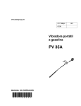
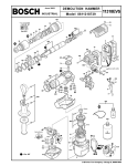
Petrol post driver
Safety and Operating Instructions
Warning: Do not operate throttle while the tool is not
on a post and between 5-10kg pull down force on handles!
Introduction
Thank you for choosing a product from Christie Engineering. We are proud to introduce our engine
driven steel fence post driver which was designed by Christie Engineering in Australia for use in the
toughest conditions.
Through the years, we have developed innovative and ergonomic product designs that have helped
customers improve and rationalize their daily work.
Christie Engineering has a strong sales and service network as a Honda approved OEM, consisting of
customer centers and distributors Australia wide.
For more information please visit: www.christieengineering.com.au
Safety and operating instructions
The aim of the instructions is to provide you with knowledge of how to use the machine in an efficient,
safe way. The instructions also give you advice and tell you how to perform regular maintenance on
the tool.
Before using the tool for the first time you must read these instructions carefully and understand all of
them.
Warning
Sudden or unexpected movement of the machine may occur during operating, which may cause
injuries. Furthermore, losing your balance or slipping may cause injury. To reduce risks:
Make sure that you always keep a stable position with your feet as far apart as the width of your
shoulders, and keeping your body weight balanced.
Stand firmly and always hold on to the machine with both hands.
Do not start the machine when it is lying on the ground.
Make sure that the handles are clean and free from grease and oil.
Personal Protective equipment (PPE)
Always use approved protective equipment. Operators and all other persons in the working area must
wear protective equipment, including at a minimum:
Hearing protection minimum Class 4 Greater than 22dB attenuation.
Impact resistant eye protection with side
protection.
Protective gloves.
Protective boots.
Noise hazard Warning
High sound levels may cause permanent hearing loss. Use hearing protection in accordance with
occupational health and safety regulations, a class 4 greater than 22dB attenuation is recommended.
Noise emitted from the tool while working can reach above 100dB which can also harm others in close
vicinity so consider this while operating and supply hearing protection when required.
Electrical/concealed object hazards Warning
Whilst driving posts, concealed wires and pipes constitute a danger that can result in serious injury.
Before you start using the tool, check the composition of the material you are to work on.
Watch out for concealed cables and pipes e.g. electricity, telephone, water, gas and sewage lines etc.
If the tool seems to have hit a concealed object, switch off the machine immediately.
Make sure that there is no danger before continuing.
Dial 1100 (Dial before you dig) if you are using the post driver in a built up area and are unsure of the
location of services. This is a service that is used by industry Australia wide.
Vibration hazard Warning
Normal use of the machine exposes the operator to vibration. Regular and frequent exposure to
vibration may cause, contribute to, or aggravate injury or disorders to the operator’s fingers, hands,
wrists, arms, shoulders and/or other body parts, including debilitating and/or permanent injuries or
disorders that may develop gradually over periods of weeks, months, or years. Such injury or disorder
may include damage to the blood circulatory system, damage to the nervous system, damage to
joints, and possibly damage to other body structures. If numbness, tingling, pain, clumsiness,
weakened grip, whitening of the skin, or other symptoms occur at any time, when operating the
machine or when not operating the machine, do not resume operating the machine and seek medical
attention. Continued use of the machine after the occurrence of any such symptom may increase the
risk of symptoms becoming more severe and/or permanent. The following may help to reduce
exposure to vibration for the operator: Let the tool do the job. Use a minimum hand grip consistent
with proper control and safe operation. When the impact mechanism is activated, the only body
contact with the machine you should have is your hands on the dampened handles. Avoid any other
contact, e.g. supporting any part of the body against the machine or leaning onto the machine trying to
increase the feed force. It is also important not to keep the trigger engaged while extracting the tool
from the steel post. Immediately stop working if the machine suddenly starts to vibrate strongly. Before
resuming the work, find and remove the cause of the increased vibrations.
Additional vibration information
This machine may cause hand-arm vibration syndrome if its use is not adequately managed.
Vibrations from handheld machines are transmitted into the hands via the handles.
The sprung handles on the Christie Engineering post driver are designed to dampen a large part of the
vibrations. Although vibrations are not eliminated completely, the measures taken to contain vibrations
mean that the tool can operate for longer periods of time with reduced risk of progressive injury.
We recommend a program of health surveillance to detect early symptoms that may relate to vibration
exposure, so that management procedures can be modified to help prevent significant disability.
Service and maintenance
Regular maintenance is a prerequisite for keeping the machine safe and effective. Carefully follow the
operating instructions. Any damage or malfunction caused by unauthorized parts will not be covered
by Warranty or Product Liability. Change damaged parts immediately.
Replace worn components in good time. When cleaning mechanical parts with solvent, make sure to
comply with occupational health and safety regulations, and make sure that there is satisfactory
ventilation.
Engine Maintenance is to be carried out to the Honda specifications found in the attached GX35
manual. The operator needs to take careful note of all warnings and dangers also outlined in the
engine manual.
For major service to the machine, contact Christie Engineering.
OPERATING INSTRUCTIONS
To reduce the risk of serious injuries or death to yourself or others, before operating the
machine, read the safety instructions section found on the previous pages of this booklet.
Design and function
The Christie Engineering Engine powered post driver is designed to be as sturdy as possible whilst
being extremely light, powerful and fuel efficient it will drive standard Star or Y configuration posts into
the toughest ground with ease. Adapters will be available to fit 5/8 or 16mm ground rods and guide
posts.
All internals components of the tool are made from high quality materials that are precision machined
to give the longest component life possible.
The design of the machine has also taken the user into account with ergonomic handles that are
sprung dampened for fatigue free operation.
Actions before starting
The following checks should be made each time you start to use the post driver:
Check engine oil
Check fuel level
Visual check striker
Visual check all fasteners
Refer to Honda GX35 manual. Use SAE 10W-30 oil
to top up.
Use regular unleaded fuel only
Look in the barrel of the device to check for damage
to the striker or barrel.
Tighten as necessary
Safe Starting
You should always inspect your post driver before starting it. Make sure the controls and safety
devices are working properly.
Place the machine on firm ground or other solid surface in an open area. Maintain good balance and
secure footing.
! NOTE when you pull the starter grip, do not wrap starter rope around your hand.
Do not allow grip to snap back, but guide starter rope slowly back to permit rope to
rewind properly.
Failure to follow this procedure may result in injury to hand or fingers or may damage the starter
mechanism.
! WARNING Start and operate your unit outdoors and in a ventilated area.
Keep the space behind and beside the engine clear at all times to allow for the escape of hot and toxic
exhaust fumes. Operate your machine under good visibility and daylight conditions only. Work
carefully.
Driving in a Post
Start motor safely as above.
Put on Personal protective equipment as described in this manual – Gloves, hearing protection, safety
boots and glasses.
Stand the post in the correct position along the line of fence by lightly tapping the post into the ground
with a hammer. This is best done in batches to speed up the process. A guide wire can be used for a
straight fence line.
Lift the post driver over the post and ensure the post is in the vertical position and the post driver in a
parallel plane to the post. Pull down on the hammer unit gently – this helps the internal hammer
mechanism to the correct operating position.
Gently pull the throttle trigger until the hammer action is felt. The post will then be driven into the
ground. When you are sure the post is moving into the ground suitably, depress the throttle trigger
fully and drive the post into the ground to the required depth.
When the post is at the required depth, gently slide the tool off the post and move to the next post and
repeat the above process leaving the motor idling.
Refueling
Always switch off the motor and allow adequate time to cool down before refueling.
Use regular unleaded fuel only.
Fill the tank on level ground avoiding spilling fuel on the motor. Always allow any spilt fuel to evaporate
before restarting the motor.
Ensure fuel cap is tightened adequately before restarting the motor.
! WARNING Fuel vapors are extremely flammable and can cause severe injury or
death if ignited by a spark or excessive heat from a hot motor.
Maintenance
Your post driver has been manufactured using high quality components which should give you many
hours of maintenance free operation, but some regular maintenance will keep your tool in good order.
10 hours
Change motor oil (Use 10W-30 oil only)
Check all bolt tightness and striking surfaces visually
50 hours
Remove front cover of crank housing and check grease. The crank
area should look clean and grease visible around the crank area
and top of piston. If there is very little grease visible add
approximately FOUR teaspoons of Caltex EP grease C0.
If using tar coated steel pickets, residue may be left in the barrel
causing the bottom striker to foul. This can be dissolved with a WD
spray up the barrel.
500 hours
or 6 months
with heavy use
Strip the driver and check gears and bearings in main reduction
box and repack with Caltex EP grease C0. Replace worn parts as
necessary. Remove striking components from main body and
check for wear or damage and replace if necessary.
Replace all O rings in unit. A kit is available from Christie
Engineering for basic servicing with O rings and grease.
! NOTE the amount and type of grease used is critical for the performance and
service life of your post driver. Not enough grease will cause failure and too much
grease will affect the striking power of the tool.
If you are unsure of anything in this manual please contact Christie Engineering to
clarify.
WARRANTY: Christie Engineering Pty Ltd warrants this machine from faults for a period of One year from date of purchase. The warranty
extends to the original retail purchaser only and commences on the date of the original retail purchase.
Any part of the Post driver manufactured or supplied by Christie Engineering and found in the reasonable judgment of Christie Engineering to be
defective in material or workmanship will be repaired or replaced by an authorized service dealer without charge for parts.
For warranty procedure for Honda engine please refer to separate engine warranty available from your nearest authorised Honda dealer who will
also carry out any engine service required.
Proudly sold by:
Christie Engineering Pty Ltd
123 Delaware Road Horsley Park NSW 2175
Ph/Fax: 02 9620 1208
ABN 56 002 534 474
Web: www.christieengineering.com.au
Email: [email protected]
Servicing details for Christie Post Driver
Tools required:
M3 and M6 Allen key
13/16 (21mm) spark plug socket and ratchet
Loctite thread locking compound
Turpentine solvent
Supplied grease
Checking hammer crank lubrication
Crank area
Remove the 4 screws from the crank cover plate using an M3 Allen key and remove
the cover. Inspect the amount and colour of grease in the crank area.
There should be a liberal amount of grease coated around the outside of the crank
about 6-8mm thick. If the grease looks to be low please add a small amount from the
supplied grease container – ¼ of the container is sufficient. The colour of the grease
may be black if using tar coated star posts and the unit will need further stripping as
described below.
Removal and servicing of hammer section
Bottom barrel top view
Damper
Remove the 4 Allen head bolts from the bottom barrel section using an M6 Allen key
and carefully slide the bottom barrel section from the cast housing.
Remove the damper section and inspect for wearing in the rubber dampers and steel
components.
The outer hub ring for the damper may show signs of wearing and if deemed too
badly worn as in the below picture may need replacing
Damper cup
Worn Damper ring
Damper
Top Striker
Guide
Ring
Damper
Bottom striker
Remove bottom striker (dolly that hits the post) and inspect the Viton O ring seal for
wear or damage and replace if necessary. The striker component is made from high
quality tool steel and should not be a wearing component but ensure a visual
inspection is carried out after cleaning for damage and replace if necessary.
To remove the top striker, gently tap the main cast housing vertically down on a soft
bench top and it should slide out of the barrel. Take note of the orientation of the
striking components as in the above right hand picture Inspect the Viton O ring for
wear and damage as per the bottom hammer.
If the hammer is damaged, the top piston can be removed from the crank by
removing the Left hand thread crank pin from the crank and gently push the plastic
piston through the bottom of the housing. Orientation is not critical on this
component. Check piston and Viton O ring for obvious signs of wear and replace if
necessary. Wash all grease from the housing and components using a turpentine
solvent and inspect the inner barrels for wear and deep scores. If too badly worn the
hammer can be sent back for repair or re-honing/replacing inner barrel.
Assembly of hammer
After thoroughly cleaning and drying the hammer components and checking for
excessive wear, reassembly can be done.
Apply a wipe of grease around O ring and outside of the plastic piston and gently
push back into the housing using a soft dolly. Add a small amount of grease to the
crank pin and reassemble remembering it is Left hand thread. Do not over tighten
this pin.
Next add a wipe of grease to the outside of top striker and gently push into the
housing – the O ring will be at the top.
For the bottom hammer section, add a light coating of grease to the bottom hammer
then push the bottom hammer into the guide tube. Next, reassemble the damper cup
with a small amount of grease to all components.
The centre “Guide ring” should be oriented correctly with the side
with the large chamfer facing down towards the bottom striker.
The hammer will be damaged if this is not correctly installed.
Install the damper back over the bottom striker.
Install bottom guide section back into the main housing ensuring
the thin section O ring is not damaged between the housings
and insert handlebars and springs back into the bottom housing. Apply Loctite to the
4 retaining screws in the bottom barrel and tighten. Apply half of the supplied grease
to the crank area and reinstall the 4 Allen screws using Loctite.
Please call Christie Engineering if there are any servicing questions or parts required
on 0296201208.