1
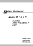
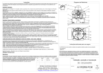
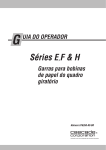
Manufactured By ROBAND AUSTRALIA PTY LTD OPERATING INSTRUCTIONS REFRIGERATED FOOD BARS & BAIN MARIES Models BR Series Version 4 ERX Series Version 5 CRX Series Version 4 SRX Series Version 3 Includes ..F.. Models (no Condenser) Special Features: Carel Electronic Controller Refrigerated Cold Plate and Cross Fin Technology Quiet Operation Stainless Steel Construction These instructions cover the models of ROBAND® Refrigerated Food Bars and Bain Maries listed above only. Although there are slight variances between models, the installation, operation, care and maintenance procedure is the same for all. 13/04/2015 Roband® Australia is a wholly Australian owned company and has been manufacturing quality commercial catering equipment for the food service industry for more than 50 years. Roband products are engineered and manufactured to the highest standards to provide functionality, reliability and durability, and our quality products are exported world-wide. Included in the comprehensive Roband® range are Toasters, Fryers, Milkshake Mixers, Rotisseries, Food Display Cabinets and much more. Roband® Australia also acts as the Australian agents for Vitamix® Blenders, Noaw® Meat Slicers, Förje® Cookware, RobalecTM Soup/Rice Warmers, Robatherm Urns, Austheat® Fryers, Dipo Induction & Autofry Machines. Roband also has its own line of commercial cookware and cutlery under the Robinox® brand name. For a complete set of brochures please contact your nearest authorised dealer or contact Roband directly at our head office. Roband Head Office Sydney, Australia Roband Australia Pty Ltd 1 Inman Road Dee Why NSW 2099 AUSTRALIA Tel: +61 2 9971 1788 Fax: +61 2 9971 1336 Email: [email protected] Web: www.roband.com.au International Agents For additional agents please email Head Office Cyprus: Fiji: Hong Kong: Malaysia: Maldives: New Zealand: Noumea: Papua New Guinea: Singapore: United Catering Equipment Supplies Ph: +357 777 777 24 Hotel Equipment Ltd Ph: +679 672 0666 Chung Wah Kitchen Machine Ltd Ph: +852 2334 5411 Allied Food Equipment Ph: +603 9133 5833 Radiant Heat Maldives Pty Ltd Ph: +960 333 4845 Roband New Zealand Ph: +649 274 1354 Comptoir Materiel Professionnel Ph: +687 28 50 43 Brian Bell & Company Pty Ltd Ph: +675 325 5411 Allied Foodservice Equipment Ph: +65 62525880 Switzerland: Thailand: United Arab Emirates: United Arab Emirates: United Kingdom: USA: USA: NETHERLANDS GREECE Burgi Infra Grill Ph: +41 418 554 552 Seven Five Distributors Co Ltd Ph: +662 866 5858 Boncafe Middle East LLC +9714 282 8742 Nisa Trading LLC +9714 396 6132 Metcalfe Catering Equipment Ph +44 1766 830 456 Condon & Fisher International Ph: +1 508 361 9226 Condon & Fisher International Ph: +1 508 361 9226 AKB Bert Muller Ph: +31 306 017 442 K&N Engineers Ltd Ph: +30 210 520 0440 © Copyright 2014 – Roband® Australia Pty Ltd All rights reserved. No part of this work may be reproduced or copied in any form or by any means, electronic or mechanical, including photocopying or posting to a website, without the written permission of the publisher. The material contained within this document is intended entirely for instructional purposes. CONTENTS INTRODUCTION ..................................................................................................... 1 GENERAL PRECAUTIONS ..................................................................................... 1 PACKAGING ........................................................................................................... 2 COMPLIANCE ......................................................................................................... 2 MODELS WITHOUT CONDENSING UNITS ........................................................... 2 IMPORTANT CONSIDERATIONS BEFORE INSTALLATION ................................. 3 INSTALLATION ....................................................................................................... 4 OPERATION............................................................................................................ 5 GENERAL SAFETY ................................................................................................. 7 SAFETY GLASS ...................................................................................................... 7 CLEANING, CARE & MAINTENANCE .................................................................... 8 TROUBLESHOOTING ............................................................................................. 9 SPECIFICATIONS ................................................................................................. 10 CIRCUIT DIAGRAM............................................................................................... 11 ELECTRONIC CONTROLLER- INSTRUCTIONS .................................................. 12 OPERATING PARAMETERS ................................................................................ 14 ALARM CODES..................................................................................................... 15 SPARE PARTS...................................................................................................... 16 WARRANTY .......................................................................................................... 20 INTRODUCTION Congratulations on your purchase of this quality ROBAND® product. With proper care and management your new purchase will give you years of trouble free service. By reading these instructions carefully you can ensure that this machine is used and maintained properly, helping your new investment to perform well for you now, and to continue performing in the many years to come. GENERAL PRECAUTIONS This machine must only be operated by qualified person(s) who are fully versed in the operating and safety instructions described in this manual. Service personnel should be instructed to familiarise themselves with any and all safety instructions described in this manual prior to commencement of any maintenance or service. In the case of new personnel, training is to be provided in advance. These machines should not be operated by children or the infirm without adequate supervision. The machine should be disconnected from all power and allowed to cool before cleaning. Roband will accept no liability if; Non-authorised personnel have tampered with the machine. The instructions in this manual have not been followed correctly. Non-original spare parts are used. The machine is not cleaned correctly, with the right product. There is any damage to the unit. Page: 1 PACKAGING All care is taken when packing and Roband ensures that every unit is functional and undamaged at the time of packaging. The package of this unit should include: 1) One Refrigerated Food Bar or Bain Marie (appropriate model). 2) This Manual. 3) Glass Doors, if applicable to the model purchased. Any damage to the machine as a result of freight must be reported to the Freight Company and to the agent responsible for the dispatch of said unit within 24 hours of receipt. No claims will be accepted or entertained after this period. COMPLIANCE RCM: Roband® products have been designed and manufactured to comply with any and all specifications set out by the Australian Communications and Media Authority (ACMA) in regards to Electromagnetic Compatibility. As testament to such compliance these units bear the RCM symbol. For further information contact the Australian Communications Authority, PO Box 13112, Law Courts, Melbourne VIC 8010. MODELS WITHOUT CONDENSING UNITS These instructions apply specifically to the refrigerated food bars and bain maries which are supplied complete with the refrigeration condensing unit mounted beneath the unit. However, the information contained in these instructions is also applicable to food bars and bain maries which are supplied ready for connection to a condensing unit in a remote location on site. The model prefixes for these units are BF, EFX, CFX, AND SFX. Only qualified, licensed, refrigeration mechanics are to carry out the piping and commissioning of remote systems and the servicing of all units. Page: 2 IMPORTANT CONSIDERATIONS BEFORE INSTALLATION We want your Foodbar to work perfectly for your application so please take the time to consider these points before you install. Incorrect installation or application may create operational issues, increase service costs, or void warranty. Consider how the Foodbar is to be used. These units are designed for the holding and displaying of food immediately prior to sale. They are not designed for long term storage of food. All product placed in the units should be prechilled to a temperature of 5°C or less, and should not be heaped high above the top of the pan. A refrigerator/cool room should be used for product long term storage, pre-chilling, and storage of bulk quantities not likely to be consumed quickly. Consider the temperature and humidity of the location. These units are designed to operate in 25°C, 60% RH (Climate Class 3) ambient environment. If the ambient temperatures and/or humidity are higher than these levels the Foodbar may not be able to keep product cooled to the required temperature. Note that customers and employees will not enjoy high temperature and humidity either, so air conditioning or ventilation should be a natural consideration in any situation. Consider the location of other hot machines near the Foodbar. Ensure that radiant and/or convected heat caused by other machines is not in the vicinity of the Cold Foodbar. Consider how the condensing unit space will be ventilated and kept cool. If the condensing unit (the box under the Foodbar) is located inside an enclosed bench/cabinet space there MUST be good ventilation to this space. Ventilation to the space should be present in at least two areas of the cabinet/bench to allow a cross-flow of air passed the condensing unit walls. Each vent area needs to have openings at least equivalent to a 250mm x 250mm square. Do not install hot equipment inside the condensing unit space. Consider how to access the condensing unit for service and cleaning. The condensing unit has three removable panels for service & cleaning. Access to the “control side” panel, held by screws, is required for service. Access to the “condenser coil” panel, which is easily removed by hand, is required for routine cleaning of the condenser coil, which is very important. Failure to allow easy access will increase service costs. The condensing unit area should be kept clean to minimise dust and/or grease build-up on the condenser coil. Consider the clearance around the condensing unit during operation. A good amount of clearance is required around the sides of the condensing unit to ensure ventilation is not obstructed during operation. At least 300mm clearance is required on the condenser coil side. At least 100mm clearance is required around each other side, and the base. Do not install or place any item within these clearances. Page: 3 INSTALLATION *** READ IMPORTANT CONSIDERATIONS BEFORE INSTALLATION *** The unit should not be tipped over prior to installation as this could cause oil to run out of the compressor, leading to problems on start-up. If this has occurred, the unit should be left idle for a period of 30-60 minutes before it is run for the first time. Always handle the Foodbar carefully during installation. Do not drop the Foodbar or subject it to impact or vibration, because it could crack the joins in the refrigeration pipework, or break glass. Remove all the packaging materials and tape, as well as any protective plastic from the machine. Clean off any glue residue left over from the protective plastic or tape using methylated spirit. The units are designed to be mounted o On a bench top with the condensing unit located through a hole in the bench top. o By being supported at each end of the Foodbar. If this latter method is utilised, the ends of the unit should be secured to prevent it from being dislodged. o On a trolley. Standard or Island trolleys, designed for Roband Foodbars, are available. Before connecting the unit to the power supply, ensure that the light switch and the refrigeration switch is in the "OFF" position. For all models plug the unit into a standard, single phase, 10 Amp power point. It is highly recommended that any doors stay on these machines at all times while in use, and kept shut whenever practical. (BR units: These should be built into a suitable enclosure, typically with doors provided; otherwise product will not stay cool). Once installed, the unit should be loaded with stainless steel pans, 65mm deep. The use of polycarbonate or plastic pans will insulate the food and reduce the cooling – these pans should not be used in these machines. If a tray race is being fitted to with your unit use extreme caution when drilling into the legs, as described in the tray race fitting instructions, to avoid damaging either electrical wiring or refrigeration pipe work housed in the legs. Page: 4 OPERATION This information is clearly stated in Roband marketing material and should have been considered prior to purchase. In cold areas the unit must be allowed to assume a temperature greater than 10°C before it is started for the first time. This will prevent lubrication problems caused by high oil viscosity in the compressor. The refrigeration unit on all models is controlled by the switch with the built in green indicator light on the control panel. The overhead fluorescent light is controlled by the switch with the built in white indicator light on the control panel. Once started, the refrigeration unit will cycle automatically under the control of the electronic controller to maintain the space temperature at approximately 5°C. Pre-cooling the unit for approximately 45 minutes is suggested prior to placing the pre-chilled food in the pans. The controller displays the current temperature of the space beneath the pans in degrees Celsius. From the factory, the set point is 2°C with a differential of 2°. This means that the cooling equipment will switch on at 4°C and off again at 2°C. The set point of the controller may be altered to suit individual applications; however, these initial settings should be an adequate starting point. We recommend that the unit be used with these factory settings initially to enable you to ascertain whether or not a change is necessary. The controller will accept a minimum set point of 0°C and a maximum set point of 10°C. For details on how this is achieved, refer to the controller manufacturer’s instructions on page 14 of this document. As a quick guide refer to the extract in the figure below. Page: 5 During operation it is important that all pans are in place. The use of plastic pans is not recommended as they inherently insulate their contents from efficient cooling. Polycarbonate and other plastic pans are not suitable for use in these displays. In Cross Fin units, the temperature of the canopy space of the food bar is determined to some degree by the amount of time that the doors are open. Care should be taken to make sure that the doors are not left open for long periods. Product stored below the top rim of the pans will be more able to stay cool when doors are opened. We recommend product should not be piled higher than the rim of the pan for this reason. Please note: The temperature display on the controller does not directly reflect the temperature of the food in the pans. To verify the food temperatures use an additional thermometer in the food directly. IMPORTANT: These units are designed for the holding and displaying of food immediately prior to sale. They are not designed as a refrigerator for long term storage of food or for continuous overnight operation. All product placed in the units should be pre-chilled to a temperature of 5°C or less. Read IMPORTANT CONSIDERATIONS BEFORE INSTALLATION. Page: 6 SAFETY GENERAL SAFETY This machine contains no user-serviceable parts. Roband Australia, one of our agents, or a similarly qualified person(s) should carry out any and all repairs. Any repair person(s) should be instructed to read the Safety warnings within this manual before commencing work on these units. Steel cutting processes such as those used in the construction of this machine result in sharp edges. Whilst any such edges are removed to the best of our ability it is always wise to take care when contacting any edge. Particular care should be taken to avoid contact with any steel edge, and warnings should be given in regards to the danger of such contact to any repair or maintenance person(s) prior to commencement of any servicing. Only service technicians should remove any screwed cover panels that may be on the machine. Note the hand removable panel to clean the condensing coil is safe to remove. Always ensure the power cable is not in contact with hot parts of the machine when in use, or other hot machines nearby. Ensure that any damaged power cord is replaced before further use. Only qualified, licensed refrigeration mechanics are to carry out the servicing of all units. SAFETY GLASS The Toughened Safety Glass used in the ROBAND® Food Bars is about five times stronger than normal glass. It is designed to completely shatter into small, relatively harmless pieces in the event of breakage. These glass pieces can be collected carefully by hand without resulting in lacerations. Note that toughened class that has suffered a large impact or stress may not immediately break, but instead shatter randomly at some time in the future - after a few minutes, or possibly years later. It is extremely rare that shattering glass would ever hurt a person nearby, although pieces of shattered glass may travel several metres. It is important to check for glass pieces across a wide area and to dispose of any contaminated food product. It is the opinion of Roband Australia that toughened glass is superior to both “Clear Float” and “Ceramic” glass with regards to function and safety. These alternatives can be very dangerous when broken, and small bits of glass could chip off and fall onto the food without being noticed. Page: 7 CLEANING, CARE & MAINTENANCE Attention to regular care and maintenance will ensure long and trouble free operation of your unit. The “Control Side” doors are removable for cleaning, and allowing easier access to the tank. To remove them, lift them up, then slide them downwards and out. Handle glass carefully. Cleaning of the body and tank should be carried out daily. To clean the unit use warm soapy water with a clean sponge or cloth. Do not use a metal scourer. It is important to turn the refrigeration unit off some time before cleaning to allow the temperature to equalise and any frost to melt. Hot water should NEVER be poured into the tank of the unit. This could crack the evaporator coil pipe work, permanently damaging the unit. When wiping out the tank, take care not to damage the probe tube located on the inside of the tank above the control panel. Ensure waste water or condensate is drained from the tank at the end of each day, or more frequently if required to avoid icing. The light fittings used are standard 18 Watt and 36 Watt fluorescent tubes (depending on the size of the food bar) which are obtainable from hardware and electrical stores. IMPORTANT: The condenser coil underneath the Foodbar should be checked regularly for build-up of dirt and/or grease. The suggested frequency is every three months, or more frequently if in a dirty environment. The condenser coil can be checked and cleaned easily by removing the hand removable cover. There should be adequate access to this removable cover. Any build-up of dirt and gunge should be removed with a long bristle brush taking care not to damage the fins of the coil. Failure to clean the condenser coil regularly could lead to reduced performance or an Alarm condition. Please note: Although every care is taken during manufacture to remove all sharp edges, care should be taken when cleaning to avoid injury. Page: 8 TROUBLESHOOTING If the Refrigerated Food Bar does not function check the following points before calling for service. If the green refrigeration switch light does not light up when turned on, check that the machine is plugged in correctly and that the power point is not faulty. If the “CHt” alarm is displayed at any time, it indicates that the condenser coil temperature is high, making it impossible for the Foodbar to work properly. A high condenser coil alarm could be caused by: Blocked condenser coil – Check that air can pass easily between the condenser coil fins. The gaps in between the fins of the condenser may need to be cleaned with a long bristle brush, to clear any gunge and dust that may have built up. Don’t damage the fins by rough handling. SEE CLEANING CARE AND MAINTENANCE Poor ventilation directly near condenser coil – check that an item has not been placed next to the coil that is blocking the airflow. Read IMPORTANT CONSIDERATIONS BEFORE INSTALLATION. Poor ventilation under bench – check that the air in the condenser unit space not getting excessively hot. There needs to be good ventilation under the bench, and hot machines should not be placed near the condenser unit. Read IMPORTANT CONSIDERATIONS BEFORE INSTALLATION. Faulty condenser fan – the fan should be spinning fast and drawing air through the coil whenever the compressor is on. If the Foodbar is not adequately cooling the product then check the environment around the Foodbar & the condensing unit, and the way the Foodbar is being used. Read IMPORTANT CONSIDERATIONS BEFORE INSTALLATION. Contact a Roband service representative only after these items have been checked. Page: 9 SPECIFICATIONS BR22 Power Source VAC 240 BR23 240 480 1030 615 255 BR24 240 500 1355 615 255 BR25 240 500 1680 615 255 BR26 240 500 2005 615 255 ERX23 240 480 1030 615 675 ERX24 240 500 1355 615 675 ERX25 240 500 1680 615 675 ERX26 240 500 2005 615 675 CRX23 240 480 1030 615 750 CRX24 240 500 1355 615 750 CRX25 240 500 1680 615 750 CRX26 240 500 2005 615 750 SRX23 240 480 1030 615 750 SRX24 240 500 1355 615 750 SRX25 240 500 1680 615 750 SRX26 240 500 2005 615 750 Model Power Rating - W Width mm Depth – mm Height mm 480 705 615 255 Constant Research & Development may necessitate machine changes at any time. Page: 10 CIRCUIT DIAGRAM MODELS: BR SERIES UNITS, CRX SERIES UNITS, ERX SERIES UNITS & SRX SERIES UNITS Carel PJEZ connections. NOTE: This circuit diagram has been provided for reference and to assist qualified service and repair agents only. Under no circumstances should person’s not suitably qualified attempt repairs to any electrical equipment. Please note that BR series units are not supplied with a fluorescent lamp. Page: 11 ELECTRONIC CONTROLLER- INSTRUCTIONS Page: 12 Page: 13 OPERATING PARAMETERS Code Parameter Unit Type Min Max Default /2 Probe measurement stability - C 1 15 4 /4 Select display probe - F 1 3 1 /5 Select ºC or ºF (0=ºC) - C 0 1 0 /6 Decimal point (0=enabled,1=disabled) - C 0 1 0 /C1 Calibration of probe 1 ºC/ºF F -127 +127 0 /C2 Calibration of probe 2 ºC/ºF F -127 +127 0 /C3 Calibration of probe 3 ºC/ºF F -127 +127 0 St Temperature set point ºC/ºF S r1 r2 4 2 rd Controller differential ºC/ºF F 0 19 2 2 r1 Minimum Set Point allowed ºC/ºF C -50 r2 -50 0 r2 Maximum Set Point allowed ºC/ºF C r1 +150 90 10 r3 Mode 0=cool with defrost, 1=cool only, 2=heating flag C 0 2 0 r4 Value to increase Set Point by from Digital Input ºC/ºF C 0 20 3 c0 Comp. and fan start delay at power up min C 0 100 0 c1 Minimum time between 2 comp starts min C 0 100 0 c2 Minimum compressor OFF time min C 0 100 0 c3 Minimum compressor ON time min C 0 100 0 c4 Duty setting min C 0 100 0 cc Duration of continuous cycle hours C 0 15 4 c6 Alarm bypass after continuous cycle hours C 0 15 2 d0 Defrost type (0=elec/temp, 1=H.Gas/temp - C 0 4 0 Roband Default -3 2=elec/time,3=hot gas/time) dl Interval between defrosts (if not using real time) hours F 0 199 8 dt End defrost temperatire, (If d0=0 or 1) ºC/ºF F -50 127 4 dP Maximum defrost duration min F 1 199 30 d4 Defrost at power up (0=disabled,1=enabled) - C 0 1 0 d5 Defrost delay at power up (If d4=1) min C 0 199 0 16 30 d6 Display during def. (0=dF [flash],1=locked) - C 0 1 1 dd Dripping time after defrost min F 0 15 2 d8 Bypass alarms after defrost hours F 0 15 1 d8d Alarm delay after door open - from dig input hours C 0 250 0 d9 Defrost priority over compressor protection - C 0 1 0 d/ Display defrost probe temp d/1=def P1,d/2=def P2 ºC/ºF F - - - dC Time basis for defrost (0=hr/min, 1=min/sec) - C 0 1 0 A0 Alarm and fan differential ºC/ºF C -20 20 0 AL Low alarm temp (if A0=<0 absolute,if A0>0 relative) ºC/ºF F -50 150 -50 AH High alarm temp (if A0=<0 absolute,if A0>0 relative) ºC/ºF F -50 150 150 Ad Low and high temperature alarm delay min C 0 199 0 A4 Configuration of digital input 1 - C 0 11 0 A7 External alarm delay if using digital input min C 0 199 0 A8 Enable alarm 'Ed' (defrost end on time) flag C 0 1 0 Ac High condensor temperature alarm set point ºC/ºF C -50 150 70 47 AE High condensor temperature alarm differential ºC/ºF C 0.1 20 5 1 10 Page: 14 OPERATING PARAMETERS CONTINUED Acd High condensor temperature alarm delay min C 0 250 0 F0 Enable evaporator fan control flag C 0 1 0 F1 Evaporator fan control set point ºC/ºF F -50 127 5 F2 Fans cycle with comp (0=disabled,1=enabled) flag C 0 1 1 F3 Fans in defrost (0=enabled,1=disabled) flag C 0 1 1 Fd Fans delay after dripping min F 0 15 1 H0 Serial address - C 0 207 1 H1 AUX output configuration flag C 0 3 0 H2 Enable keypad (0=enabled,1=disabled) flag C 0 1 1 H4 Disable buzzer (0=enabled,1=disabled) flag C 0 1 0 H5 ID code (read only) flag F 0 31 - EZY Select set of default parameters (settings below) - C 0 4 0 1 normal temperature, no defrost 2 normal temperature with timed defrost 3 normal temperature, heated output 4 normal temperature, defrost controlled by temp (d0=4) 15 ALARM CODES Alarm Code Description LED Buzzer Alarm Parameters involved E0 probe 1 error (control) ON ON ON - E1 probe 2 error (defrost) ON OFF OFF d0=0/1/4 , F0=1 E2 probe 3 error (cond) ON OFF OFF A4=10 IA external alarm ON ON ON A4=1 , +A7 dOR open door alarm ON ON ON A4=7/8 , +A7 LO low temperature alarm ON ON ON AL , Ad HI high temperature alarm ON ON ON AH , Ad EE unit parameter error ON OFF OFF - EF operating parameter error ON OFF OFF - Ed defrost ended by timeout ON OFF OFF dP , dt , d4 , A8 dF defrost running OFF OFF OFF d6=0 cht Condenser over temp. pre-alarm ON OFF OFF A4=10 CHt Condenser over temp alarm ON ON ON A4=10 EtC clock alarm ON OFF OFF If bands active Page: 15 SPARE PARTS COMMON PARTS Models Part Number Description All Models EC0016 Switch - Rocker, amber indicating All Models EC0028 Terminal Block - 2 Screw, 6 Spade (QC) A & N All Models EC0158 Switch - Rocker, Black (30mm x 11mm) All Models EC0288 Switch - Rocker, On/Off Green - Suits TC0030 All Models EC0289 Switch - Rocker, Light White - Suits TC0030 All Models MC0087 Thermometer - minus 40 to 40°C All Models MC0149 Valve - Drain, 1/2" ball with lever All Models PC0060 Cord Clamp - 10A All Models RC0004 Sight Glass All Models RC0005 Filter Drier All Models RC0006 TX Valve c/w size 0 orifice - Int Eq. All Models TC0030 Electronic Temperature Controller - Carel All Models TC0031 Sensor - NTC, Carel Size 23 Specific Parts All Size 23RD MS0322 Track & Rivets - 23 - Roller Doors All CRX23 & SRX23 PS0077 Silicone - Front Glass 23 All Size 23RD VS0085 LH Roller Door Assembly 23 c/w Frame & Glass All Size 23RD VS0091 RH Roller Door Assembly 23 c/w Frame & Glass Size 24 Specific Parts All Size 24RD MS0323 Track & Rivets - 24 - Roller Doors All CRX24 & SRX24 PS0078 Silicone - Front Glass 24 All Size 24RD VS0086 LH Roller Door Assembly 24 c/w Frame & Glass All Size 24RD VS0092 RH Roller Door Assembly 24 c/w Frame & Glass Size 25 Specific Parts All Size 25RD MS0324 Track & Rivets - 25 - Roller Doors All CRX25 & SRX25 PS0079 Silicone - Front Glass 25 All Size 25RD VS0087 LH Roller Door Assembly 25 c/w Frame & Glass All Size 25RD VS0093 RH Roller Door Assembly 25 c/w Frame & Glass Size 26 Specific Parts All Size 26RD MS0325 Track & Rivets - 26 - Roller Doors All CRX26 & SRX26 PS0080 Silicone - Front Glass 26 All Size 26RD VS0088 LH Roller Door Assembly 26 c/w Frame & Glass All Size 26RD VS0094 RH Roller Door Assembly 26 c/w Frame & Glass BR Specific Parts Models Part Number Description All BR MS0064 Drain Pipe Assembly - 1/2 " Ball Valve, ERX Series Page: 16 CRX Specific Parts Models Part Number Description CRX23 GC0029 Glass - Front, Toughened CRX24 GC0030 Glass - Front, Toughened CRX25 GC0031 Glass - Front, Toughened CRX26 GC0032 Glass - Front, Toughened All CRX GC0049 Glass - Side, 38mm leg (post March 99) All CRX MS0062 Drain Pipe Assembly - 1/2 " Ball Valve, CRX Series All CRX PS0075 Silicone - Side Glass All CRX PS0081 Silicone - Top All CRX PS0109 Silicone - Vertical on Front Glass ERX Specific Parts Models Part Number Description ERX22 GC0011 Glass - Front ERX23 GC0012 Glass - Front ERX24 GC0013 Glass - Front ERX25 GC0014 Glass - Front ERX26 GC0015 Glass - Front All ERX GC0017 Glass - Side All ERX MS0064 Drain Pipe Assembly - 1/2 " Ball Valve, ERX Series SRX Specific Parts Models Part Number Description All SRX GC0102 S Series Foodbar Side Glass - 5mm Toughened SR22 GC0103 Top Glass - 8mm Toughened SR23 GC0104 Top Glass - 8mm Toughened SR24 GC0105 Top Glass - 8mm Toughened SR25 GC0106 Top Glass - 8mm Toughened SR26 GC0107 Top Glass - 8mm Toughened SR22 GC0108 Front Glass - 6mm Toughened SR23 GC0109 Front Glass - 6mm Toughened SR24 GC0110 Front Glass - 6mm Toughened SR25 GC0111 Front Glass - 6mm Toughened SR26 GC0112 Front Glass - 6mm Toughened All SRX MS0062 Drain Pipe Assembly - 1/2 " Ball Valve, CRX Series All SRX PS0075 Silicone - Side Glass All SRX PS0081 Silicone - Top Page: 17 Condensing Units - Complete Models Part Number Description BR22-24 RC0001 Condensing Unit Complete BR25-26 RC0002 Condensing Unit Complete CRX23 RC0002 Condensing Unit Complete CRX24 RC0029 Condensing Unit Complete CRX25-26 RC0032 Condensing Unit Complete ERX23 RC0002 Condensing Unit Complete ERX24 RC0029 Condensing Unit Complete ERX25-26 RC0032 Condensing Unit Complete SRX23 RC0002 Condensing Unit Complete SRX24 RC0029 Condensing Unit Complete SRX25-26 RC0032 Condensing Unit Complete Page: 18 NOTES (Record any preferred times or settings etc. here to act as a quick reference for other users) Page: 19 WARRANTY Every care is taken to ensure that no defective equipment leaves our factory and all goods manufactured by us are guaranteed against defective workmanship and materials for a period of 12 months from the date of purchase. Roband Australia’s obligations pursuant to this express warranty being limited to the repair or replacement of the defective goods or materials, at is option and subject to the terms contained within this Warranty statement. Where relevant, glass, Teflon® and lamps are not included in this warranty and RCD tripping due to moisture absorption by Tubular Heating Elements is not considered a warranty fault. Generally, all goods claimed under this warranty must be returned to the factory or an authorized service agent, freight prepaid, for inspection. All parts deemed to be defective will be replaced, however, no claims will be entertained for second hand products, or parts damaged in transport, misused or modified in any way without our approval. For machines that are not considered to be portable (e.g. food bars, rotisseries, large hotplates and some bain maries), on site warranty service will be provided in capital city metropolitan areas only. In all other locations, the customer is responsible for all travelling time/service call costs and payment for this will be required prior to the commencement of the repair. The labour costs to actually repair the fault will be met by the company. Any repairs or replacement of defective goods or materials pursuant to this warranty, must be authorized by Roband Australia prior to any action being taken. The company reserves the right to reject a claim for warranty if it is not completely satisfied with the circumstances under which it occurred and any other costs incurred for false claims or faults due to incorrect usage etc. are the responsibility of the claimant. Roband Australia Pty Ltd nor any subsidiary company or Agent shall be liable for loss of profit or damage to other equipment and property except where it is in breach of the guarantees provided in accordance with Schedule 2 of the Competition and Consumer Act 2010 (Cth) or the applicable legislation from time to time. The goods come with guarantees that cannot be excluded under the Australian Consumer Law (ACL). You are entitled to a replacement or refund for a major failure and for compensation for any other reasonably forseeable loss or damage. You are also entitled to have the goods repaired or replaced if they fail to be of acceptable quality and the failure does not constitute a major failure. Generally, authorized service agents are located in all areas which have authorized distribution dealers. For the name of your nearest Australian authorised service agent, please contact: Roband Australia Pty Ltd 1 Inman Road, Cromer, NSW 2099 Warranty Number: 1800 268 848 Phone: (02) 9971 1788 Fax: (02) 9971 1336 All other countries please contact your selling Agent. Please complete the following details and keep this card in a safe place. NAME ADDRESS MODEL No: SERIAL No: DATE PURCHASE NAME OF DEALER: PLEASE RETAIN THIS SECTION FOR YOUR RECORDS DO NOT POST ROBAND® AUSTRALIA PTY LTD Page: 20