1
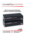
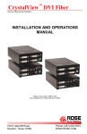
CrystalView Pro™ CAT5 DIGITAL CAT5 KVM EXTENDER INSTALLATION AND OPERATIONS MANUAL 10707 Stancliff Road Houston, Texas 77099 Phone: (281) 933-7673 WWW.ROSE.COM LIMITED WARRANTY Rose Electronics warrants the CrystalView Pro CAT5 to be in good working order for one year from the date of purchase from Rose Electronics or an authorized dealer. Should this product fail to be in good working order at any time during this one-year warranty period, Rose Electronics will, at its option, repair or replace the Unit as set forth below. Repair parts and replacement units will be either reconditioned or new. All replaced parts become the property of Rose Electronics. This limited warranty does not include service to repair damage to the Unit resulting from accident, disaster, abuse, or unauthorized modification of the Unit, including static discharge and power surges. Limited Warranty service may be obtained by delivering this unit during the one-year warranty period to Rose Electronics or an authorized repair center providing a proof of purchase date. If this Unit is delivered by mail, you agree to insure the Unit or assume the risk of loss or damage in transit, to prepay shipping charges to the warranty service location, and to use the original shipping container or its equivalent. You must call for a return authorization number first. Under no circumstances will a unit be accepted without a return authorization number. Contact an authorized repair center or Rose Electronics for further information. ALL EXPRESS AND IMPLIED WARRANTIES FOR THIS PRODUCT INCLUDING THE WARRANTIES OF MERCHANTABILITY AND FITNESS FOR A PARTICULAR PURPOSE, ARE LIMITED IN DURATION TO A PERIOD OF ONE YEAR FROM THE DATE OF PURCHASE, AND NO WARRANTIES, WHETHER EXPRESS OR IMPLIED, WILL APPLY AFTER THIS PERIOD. SOME STATES DO NOT ALLOW LIMITATIONS ON HOW LONG AN IMPLIED WARRANTY LASTS, SO THE ABOVE LIMITATION MAY NOT APPLY TO YOU. IF THIS PRODUCT IS NOT IN GOOD WORKING ORDER AS WARRANTED ABOVE, YOUR SOLE REMEDY SHALL BE REPLACEMENT OR REPAIR AS PROVIDED ABOVE. IN NO EVENT WILL ROSE ELECTRONICS BE LIABLE TO YOU FOR ANY DAMAGES INCLUDING ANY LOST PROFITS, LOST SAVINGS OR OTHER INCIDENTAL OR CONSEQUENTIAL DAMAGES ARISING OUT OF THE USE OF OR THE INABILITY TO USE SUCH PRODUCT, EVEN IF ROSE ELECTRONICS OR AN AUTHORIZED DEALER HAS BEEN ADVISED OF THE POSSIBILITY OF SUCH DAMAGES, OR FOR ANY CLAIM BY ANY OTHER PARTY. SOME STATES DO NOT ALLOW THE EXCLUSION OR LIMITATION OF INCIDENTAL OR CONSEQUENTIAL DAMAGES FOR CONSUMER PRODUCTS, SO THE ABOVE MAY NOT APPLY TO YOU. THIS WARRANTY GIVES YOU SPECIFIC LEGAL RIGHTS AND YOU MAY ALSO HAVE OTHER RIGHTS WHICH MAY VARY FROM STATE TO STATE. NOTE: This equipment has been tested and found to comply with the limits for a Class B digital device, pursuant to Part 15 of the FCC Rules. These limits are designed to provide reasonable protection against harmful interference when the equipment is operated in a commercial environment. This equipment generates, uses, and can radiate radio frequency energy and, if not installed and used in accordance with the instruction manual, may cause harmful interference to radio communications. Operation of this equipment in a residential area is likely to cause harmful interference in which case the user will be required to correct the interference at his own expense. IBM, AT, and PS/2 are trademarks of International Business Machines Corp. Microsoft and Microsoft Windows are registered trademarks of Microsoft Corp. Any other trademarks mentioned in this manual are acknowledged to be the property of the trademark owner. Copyright Rose Electronics 2002. All rights reserved. No part of this manual may be reproduced, stored in a retrieval system, or transcribed in any form or any means, electronic or mechanical, including photocopying and recording, without the prior written permission of Rose Electronics. Rose Electronics Part # MAN-CRVP5 - 1.1 Printed In the United States of America – Revision 1.2 FCC/IC STATEMENTS, EU DECLARATION OF CONFORMITY FEDERAL COMMUNICATIONS COMMISSION AND INDUSTRY CANADA RADIO-FREQUENCY INTERFERENCE STATEMENTS This equipment generates, uses and can radiate radio frequency energy and if not installed and used properly, that is in strict accordance with the manufacturer’s instructions may cause interference to radio communication. It has been tested and found to comply with the limits for a Class B digital device in accordance with the specifications of Part 15 of FCC rules, which are designed to provide reasonable protection against such interference when the equipment is operated in a commercial environment. Operation of this equipment in a residential area is likely to cause interference, in which case the user at his own expense will be required to take whatever measures may be necessary to correct the interference. Changes or modifications not expressly approved by the party responsible for compliance could void the user’s authority to operate the equipment. This digital apparatus does not exceed the Class B limits for radio noise emission from digital apparatus set out in the Radio Interference Regulation of Industry Canada. Le présent appareil numérique n’émet pas de bruits radioélectriques dépassant les limites applicables aux appareils numériques de la classe A prescrites dans le Règlement sur le brouillage radioélectrique publié par Industrie Canada. CE DECLARATION OF CONFORMITY This equipment is in conformity with the Council Directives 89/336/EEC The Declaration of Conformity is based upon compliance of the product with the following standards: EN55022 UTP 1999 class A EN55024: IEC61000-4-2: 2001 IEC61000-4-3: 2001 IEC61000-4.4: 2001 IEC61000-4-5: 2001 (Cat5 device only) EN61000-3-2 2001 EN61000-3-3 2002 TABLE OF CONTENTS Contents Disclaimer ...................................................................................................... 1 System introduction ....................................................................................... 1 Features.................................................................................................... 2 Compatibility ............................................................................................. 2 DVI or VGA ............................................................................................... 3 PC model ....................................................................................................... 4 Rack model.................................................................................................... 5 CrystalView Pro CAT5 cables ....................................................................... 6 Device Control - OSD .................................................................................... 7 Select graphic source menu ..................................................................... 8 Installation.................................................................................................... 14 Transmitter to Receiver cabling.............................................................. 15 SET-UP instructions (Mixed DVI and VGA) ........................................... 16 Applying power ....................................................................................... 18 Operating instructions.................................................................................. 19 Frame Rates ................................................................................................ 19 Troubleshooting ........................................................................................... 20 Service Information...................................................................................... 22 Safety........................................................................................................... 23 Figures Figure 1. PC model........................................................................................ 4 Figure 2. Input select menu ........................................................................... 8 Figure 3. Scale mode menu .......................................................................... 8 Figure 4. Brightness/Contrast menu.............................................................. 9 Figure 5. Color / Color temp menu .............................................................. 10 Figure 6. Image menu.................................................................................. 11 Figure 7. Tools menu................................................................................... 12 Figure 8. Save menu ................................................................................... 13 Figure 9. Typical cabling configurations ...................................................... 14 Figure 10. Pixelclock/Phase examples........................................................ 17 Tables Table 1.transmitter to receiver cabling ........................................................ 15 Appendices Appendix A. General specifications............................................................. 25 Appendix B. Parts and cables ..................................................................... 26 Appendix C. Firmware updates ................................................................... 26 Appendix D. Rack mount instructions.......................................................... 27 Appendix E. Rack mount illustration............................................................ 27 INTRODUCTION Disclaimer While every precaution has been taken in the preparation of this manual, the manufacturer assumes no responsibility for errors or omissions. Neither does the manufacturer assume any liability for damages resulting from the use of the information contained herein. The manufacturer reserves the right to change the specifications, functions, or circuitry of the product without notice. The manufacturer cannot accept liability for damages due to misuse of the product or other circumstances outside the manufacturer’s control. The manufacturer will not be responsible for any loss, damage, or injury arising directly or indirectly from the use of this product. System introduction Thank you for choosing the Rose Electronics CrystalView Pro CAT5 KVM station extender. The CrystalView Pro CAT5 is a very versatile CAT5 KVM extender. It supports the latest digital DVI as well as analog VGA. All combinations of DVI and VGA monitors and video cards are supported. With this flexibility, you can connect a VGA video card to a DVI monitor, or a DVI video card to a VGA monitor. The system consists of two Units, a transmitter and a receiver. The transmitter connects to your CPU or a Rose switch and the receiver connects to a keyboard, video monitor and mouse or KVM station. The transmitter and receiver are connected together with CAT-5 industry standard cable. The receiver can be up to 330 feet from the transmitter using CAT5 cable. The PC model is available with transmitter and receiver KVM access. The transmitter KVM version allows an additional KVM station to be connected to the transmitter unit. CRYSTALVIEW PRO CAT5 INSTALLATION AND OPERATINS MANUAL 1 Using the CrystalView Pro CAT5 to remotely access your computer has several advantages over conventional CAT-5 extenders. The CrystalView Pro CAT5 transmits data digitally which provides a clear, sharp picture. Computers used in hazardous industrial environments can be accessed remotely, keeping the users safe and unexposed to any hazards. Features Perfect image quality at resolutions up to 1600 x 1200 using CAT-5 cable Extend a KVM station from a CPU using: CAT-5 for distances up to 1,000 feet (300m) Supports PS/2 keyboards and mouse. The CrystalView Pro CAT5 uses a microprocessor to emulate the keyboard and mouse. The keyboard and mouse on the receiver do not have to be connected for the PC to boot; only the transmitter Unit must be connected to the PC. On-screen display for adjusting brightness, contrast, saturation, pixelclock, phase, and other parameters Compatible with Rose Electronics family of KVM switches such as ServeView, UltraView and UltraMatrix. Compatible with Windows, Windows NT, OS/2, Unix, Linux and other operating systems. Fully automatic KVM sharing on a first-come first-serve basis using the transmitter access model. On the transmitter access model, the computers video is displayed on both KVM stations monitors. Rack mount kits available in 19”, 23” and 24” sizes. Compatibility Computers PCs (all operating systems) Monitors Digital DVI Analog VGA, SVGA, XGA, RGB (Sync-ongreen) Keyboards PS/2 type keyboards Mouse PS/2 2 CRYSTALVIEW PRO CAT5 INSTALLATION AND OPERATIONS MANUAL DVI or VGA The CrystalView Pro CAT5 is designed to work with any combination of VGA and DVI video cards and monitors. The ideal configuration is using a DVI video card, a TFT monitor and DVI video cables. With this configuration, no adjustments are needed. A set-up procedure may be needed if you are using a VGA video card and a TFT, DVI monitor or a DVI video card and a VGA monitor. The installation section of this manual describes these procedures for different combinations of equipment and cables. Package contents The package contents consist of the following: The transmitter and receiver Units Power adapter for transmitter and receiver units. Installation and operations manual. CPU adapter cables and CAT5 cables are usually ordered separately. If the package contents are not correct, contact Rose Electronics or your reseller, so the problem can be quickly resolved. CRYSTALVIEW PRO CAT5 INSTALLATION AND OPERATINS MANUAL 3 MODELS PC model Receiver Transmitter (Local KVM access) Transmitter (No local KVM access) Shown with serial and audio options Figure 1. PC model Connectors: Receiver unit DVI-I – DVI/VGA – KVM stations video monitor connection. (2) MiniDin-6 – KVM stations keyboard / mouse connection. Link – RJ45 4-pin square – Power RJ11 – Programming DB9 – Serial data input (2) 3.5mm stereo audio input/output Transmitter unit (With Local KVM access) DVI-I – DVI/VGA – CPU video connection. DVI-I – DVI/VGA – KVM stations video monitor connection. (4) MiniDin-6 – (2) CPU keyboard and mouse connections / (2) KVM keyboard and mouse connections. Link – RJ45 4-pin square – Power RJ11 – Programming DB9 – Serial data input (2) 3.5mm stereo audio input/output Transmitter unit (No Local KVM access) DVI-I DVI/VGA – CPU video connection. (2) MiniDIN-6 – CPU keyboard and mouse connections Link – RJ45 4-pin square – Power RJ11 – Programming DB9 – Serial data input (2) 3.5mm stereo audio input/output 4 CRYSTALVIEW PRO CAT5 INSTALLATION AND OPERATIONS MANUAL Rack model The rack models consist of 1 to 10 independent units mounted in a single rack mountable chassis. Each unit is individually configured and connected to a corresponding remote or local unit. Transmitters and receivers can be installed in the same chassis. CRYSTALVIEW PRO CAT5 INSTALLATION AND OPERATINS MANUAL 5 CABLES CrystalView Pro CAT5 cables Transmitter unit to CPU cable CPU cables connect from the transmitter to a CPUs keyboard, video monitor and mouse ports. Receiver to KVM station cable The keyboard, video monitor, and mouse cables on a KVM station can connect directly to the receiver or a transmitter with local KVM access. CrystalView Pro CAT5 to Rose switch cable To connect a transmitter to a Rose switch such as a ServeView, UltraMatrix or UltraView, use a CPU adapter cable, Rose cable part number CABCX0606Cnnn. Transmitter unit to Receiver unit cable The transmitter is connected to the receiver with up to 1,000 feet of Cat-5 cable 6 CRYSTALVIEW PRO CAT5 INSTALLATION AND OPERATIONS MANUAL ON-SCREEN DISPLAY (OSD) Device Control - OSD The on-screen display provides an easy way to define the following parameters: 1. Input select, graphic source, VGA or DVI 2. Scale mode, fixed screen resolution/scale mode 3. Brightness/contrast/Back level 4. Colors 5. Color temperatures 6. Color depth 7. Image, pixelclock, phase, screen position 8. Tools, reset to factory defaults 9. Auto configuration 10. Save all settings To access the OSD feature, press the CTRL, Shift, and I key. (Initialize the On-screen display) When the OSD is active, the keyboard LED will blink, the mouse is inactive, and only the following keyboard keys are active. Valid Key Function Menu selection Action Close the OSD, release Adjusting parameters keyboard and mouse Common function on all menus Back to menu selection Menu selection Select menu function Adjusting parameters Accept selection/Start function Menu selection Previous menu selection Adjusting parameters Decrease selected parameter Menu selection Next menu selection Adjusting parameters Increase selected parameter Value bar is displayed to increase/decrease values Contrast CRYSTALVIEW PRO CAT5 INSTALLATION AND OPERATINS MANUAL 7 Select graphic source menu The Input Select menu is the first menu to display when the OSD is activated. This menu allows you to select the graphic source type. This is typically the video card type, VGA or DVI. Use the left or right arrow keys to select VGA or DVI and press [Enter}. The actual graphic source is displayed with a check mark. Figure 2. Input select menu The Scale mode menu allows you to set a fixed resolution at the receiver or use the resolution sent from the transmitter. Figure 3. Scale mode menu 8 CRYSTALVIEW PRO CAT5 INSTALLATION AND OPERATIONS MANUAL The receiver will always generate an exact reproduction of the source signal if the Fixed Resolution setting is set to “OFF”. The fixed resolution setting should be used if the monitor resolution on the receiver is not capable of displaying the resolution sent by the transmitter. If the transmitter is connected to a KVM switch with several CPUs with different video resolutions, setting the receiver to a fixed resolution eliminates the need for the receiver to adjust to the sent resolution when switching between CPUs. The received image will display faster when switching between CPUs if you use a fixed resolution setting on the receiver. Refresh rates of 60Hz are best for LCD displays; 75Hz for CRT’s. Use the arrow keys to select the needed fixed resolution setting and refresh rate, then press [Enter] to accept the new setting. The brightness / contrast menu enables you to adjust: Brightness Contrast Back level Figure 4. Brightness/Contrast menu Use the arrow keys to select the brightness, contrast, or back level Icon and press [Enter]. The adjustable scroll bar will display. Use the left and right arrow keys to increase or decrease the values. CRYSTALVIEW PRO CAT5 INSTALLATION AND OPERATINS MANUAL 9 The color and color temperature menu can automatically calibrate for the best color parameters or they can be set manually. Use the left and right arrow keys to select the needed ICON and press [ENTER]. Figure 5. Color / Color temp menu The automatic calibration adjusts for the best color parameters Standard RGB selection Select color temperature provides two options; Direct setup of each RGB color, also changes CMY colors Color temperature selections 4200K, 5000K, 6500K, 7500K, 9300K Direct setup of each CMY color, also changes RGB colors Adjusts flesh and skin tones Adjust Hue Adjust saturation Back to menu selection 10 CRYSTALVIEW PRO CAT5 INSTALLATION AND OPERATIONS MANUAL The image selection allows re-positioning of the image and for manually adjusting the number of pixels per line (pixelclock) and manually adjusting the phase. This option is only available with a VGA source. No adjustments are needed for a DVI source. Figure 6. Image menu Select to automatically detect the number of pixels per line and the best phase. Select to manually adjust the number of pixels per line (Pixelclock) Select to manually adjust for the best phase. Select to manually adjust the horizontal screen position Select to manually adjust the vertical screen position Select to return back to the main menu The tools selection allows you to adjust the OSD position, reset to factory defaults, adjust sharpness, and other parameters. CRYSTALVIEW PRO CAT5 INSTALLATION AND OPERATINS MANUAL 11 Figure 7. Tools menu Manually adjust the OSD Manually adjust the Horizontal OSD position Manually adjust the vertical OSD position OSD size – Select single or double size Reset to factory defaults Manually adjust sharpness (Only effective on fixed scaling). If you select fixed scaling to keep the resolution fixed when switching to different CPUs, some characters may not be sharp. This function allows you to enhance the sharpness in three steps for fixed scaled images. Auto-detect the number of pixels and automatically adjust the phase when switching to different CPUs with different resolutions. (See note) Auto-detect the number of pixels per line and best phase after each change in resolution. 12 CRYSTALVIEW PRO CAT5 INSTALLATION AND OPERATIONS MANUAL No auto-detection of pixels and phase Color depth of the source screen picture Low color mode: This mode allows high frame rates, select for fast screen changes (i.e. video) Transmitting on CAT-5 with 5 bits/color = 15 bits total = 32768 colors. High color mode: This mode allows for low frame rates only, select for exact picture display (i.e. medical) Transmitting on CAT-5 with 7 bits/color = 21 bits total = 2.1M colors. Note: Automatic detection of the number of pixels per line and the best phase after switching to a different CPU will ensure a properly adjusted screen picture but this process will increase the time it takes to display the screen picture. If the screen picture needs to be displayed faster and some decrease in sharpness is acceptable, or you are connected to a single CPU or server, deselect this function. On some menu settings, the save settings display will appear after making any changes. Use the left or right arrow key to select Yes or No and press enter to save the changes made. Figure 8. Save menu CRYSTALVIEW PRO CAT5 INSTALLATION AND OPERATINS MANUAL 13 INSTALLATION Installation Please refer to the safety section first before proceeding with any installation or configuration of the CrystalView Pro CAT5. NOTE: If your CPU uses a DVI video card and the KVM station’s monitor is a TFT (flat panel) DVI monitor, pixelclock and phase adjustments should not be needed. Refer to the set-up section for mixed VGA and DVI equipment installation. The CrystalView Pro CAT5’s design does not support plug & play or a private mode on the local KVM access models. When installing the CrystalView Pro CAT5, locate the transmitter as close as possible to the CPU or switch. Keep the CPU cables as short as possible but still give some freedom of movement. Using shorter VGA cables keeps the video noise to a minimum and reduces installation costs. You can mount the CrystalView Pro CAT5 in a CPU rack with the optional rack mount kit. When mounting the units in a rack, follow the instructions in Appendix D and Appendix E. Provide adequate air circulation to assure that the maximum operating temperature is not exceeded. Wherever the transmitter and receiver units are located, they should be on a secure surface and free from obstructions and objects that may cause damage to the units. A 1 2 3 Transmitter B 1 2 3 Switch C 1 2 Switch Receiver 4 Transmitter Receiver 3 Transmitter 4 Receiver 5 Switch Figure 9. Typical cabling configurations (See Figure 1, 2, or 3 for the connector locations for your model) NOTE: Using a PC model with local access, a second KVM station can be connected to the transmitter. Refer to Figure 11 for the set-up for your system application. 14 CRYSTALVIEW PRO CAT5 INSTALLATION AND OPERATIONS MANUAL A. 1- Connect the appropriate CPU cable to the keyboard, video monitor and mouse ports on the CPU and to the corresponding ports on the transmitter. 2- Connect the transmitter to the receiver with up to 1,000 feet of CAT-5 cable. 3- Connect the KVM stations keyboard, video monitor, and mouse cables to the corresponding connectors on the receiver unit. B. 1- Connect the appropriate CPU cable to the keyboard, video monitor and mouse ports on the CPU and to the appropriate CPU connector on the switch. 2- Connect the appropriate KVM cable from the KVM port on the switch to the corresponding connectors on the transmitter. 3- Connect the transmitter to the receiver with up to 1,000 feet of CAT5 cable. 4- Connect the KVM stations keyboard, video monitor, and mouse cables to the corresponding connector on the receiver unit. C. 1- Connect the appropriate CPU cable to the keyboard, video monitor and mouse ports on the CPU and to the appropriate CPU connector on the switch. 2- Connect the appropriate KVM cable from the KVM port on the switch to the corresponding connectors on the transmitter. 3- Connect the transmitter to the receiver with up to 1,000 feet of CAT5 cable. 4- Connect the appropriate CPU cable from the CPU port on the switch to the corresponding connectors on the receiver 5-Connect the KVM stations keyboard, monitor, and mouse cables to the corresponding connector on the receiver unit. Transmitter to Receiver cabling Cable type CAT-5 Maximum distance 1,000’ / 300m Table 1.transmitter to receiver cabling CRYSTALVIEW PRO CAT5 INSTALLATION AND OPERATINS MANUAL 15 SET-UP instructions (Mixed DVI and VGA) The following set-up instructions are for systems that use a mixture of VGA and DVI products. Systems with DVI video cards, DVI monitors and use DVI cables normally do not require any set-up. Set-up consists of adjusting the pixelclock first, then adjusting the phase. To properly do this, an appropriate image must be displayed on the monitor. This image should be a simple 8 x 8 pixel image with altering black and white stripes (4 black and 4 white stripes) You can create this image using a graphics package that can create a picture 8 pixels wide by 8 pixels high. Create 4 black columns 1 pixel wide by 8 pixels high and 4 white columns 1 pixel wide and 8 pixels high. Save this image in the Windows folder as Burst.bmp (C:\WINDOWS\BURST.BMP) The recommended procedure for setting the pixelclock and phase is to use the OSD, auto-detect feature. To do this, perform the following: 1. Assign the “Burst.bmp” image you created as your Windows background, and a Tiled display. The desktop should show fine black and white vertical stripes over the total desktop background. 2. Make all connections (CPU to transmitter, transmitter to receiver, and receiver unit to KVM station.) (Note: The Remote monitor should not be a TFT flat-panel monitor, it should be a VGA monitor. The CrystalView Pro CAT5 digitizes the signals and the TFT monitor also digitizes the signal. Digitizing the signals twice will product invalid results using auto-detect. Once the pixelclock and phase are adjusted, a TFT monitor can be connected.) 3. Start the OSD (CTRL + Shift + I) 4. Select Automatic detection of the number of pixels per line and the best phase” then press Enter to start the auto-detect procedure (See Figure 7). If the background image’s black and white stripes are sharp and without jitter or smearing when the auto-detect function completes, no further adjustments are needed. If there is smearing or jitter, the pixelclock and phase must be adjusted manually. 16 CRYSTALVIEW PRO CAT5 INSTALLATION AND OPERATIONS MANUAL Pixel clock set correctly Pixel clock set incorrectly Pixel clock set incorrectly Phase set incorrectly Figure 10. Pixelclock/Phase examples If one or more vertical areas have smeared lines, the pixelclock needs adjusting. If there are horizontal noise lines, flicker or smearing with a zebra-pattern, the phase needs adjusting. (See Figure 6) First, manually adjust the pixelclock. Start the OSD and select the “IMAGE” icon. Next, select the “Manually adjust the number of pixels per line” icon, then press enter. Use the left and right arrow keys to modify the pixelclock until all vertical stripes have disappeared. Press enter when the adjustment is complete. Next, manually adjust the phase setting. Select “Manually adjust the best phase”, then press enter. Use the left and right arrow keys to modify the phase until all horizontal noise lines, and any flicker or smearing with a zebra-pattern has disappeared. Press enter when the adjustment is complete. When the pixelclock and phase are adjusted, you can remove the background image and replace it with your original. CRYSTALVIEW PRO CAT5 INSTALLATION AND OPERATINS MANUAL 17 Applying power Plug in the provided power adapters to a 110/220-volt source and to the power connector on the transmitter and receiver Unit. Only use the power adapter provided. GND and earth should not be connected. Mount ferrite rings in the DC lines to protect against electromagnetic interference. Boot up the connected CPU and wait for it to completely boot-up. The two LEDs on each side of the CAT5 cable connector indicate the following: Red LED, communication status Off – no communication errors Slow blinking – one or more communication errors occurred over a 60minute period. Fast blinking – Several communication errors occurred over a 60-minute period. Green LED, Link status On – power is on and link connection is locked. Blinking – CAT5 cable not connected or damaged. The two LEDs next to the power connector indicate the following: Both LEDs on – system booted correctly. Only one LED on – unknown video mode being used. 18 CRYSTALVIEW PRO CAT5 INSTALLATION AND OPERATIONS MANUAL OPERATING INSTRUCTIONS Operating instructions Once the transmitter and receiver units are connected and configured, the KVM station will function as if it were directly connected to a CPU or KVM switch. All applications, upgrades and PC configurations can be performed normally. If your transmitter is connected to a KVM switch, refer to the switches manual for the proper method of switching to different CPU ports. Operating instructions – Local KVM access The CrystalView Pro CAT5 with local KVM access allows an additional KVM station to be connected to the transmitter. The CPU or KVM switch can easily be operated from the remote KVM station or the local KVM station but not simultaneously. The transmitter is active during boot-up and the connected CPUs video is displayed on both the transmitter and remote KVM stations monitor. To activate the receiver’s KVM station, simply press any key on the KVM stations keyboard. To activate the transmitters KVM station, press any key on the KVM station’s keyboard. Frame Rates Normally the data rate of a DVI video card is much higher than the transfer rate of the CrystalView Pro CAT5 modules, consequentially, not every frame of the graphic card is transferred. Stating with a recognized VS-signal, the next complete frame generated by the graphic card is digitized (VGA only) and temporally stored, transmitted to the receiver using the available net data rate and displayed. Images generated by the graphic card during the transfer are discarded (frame dropping). The resulting frame rate is approximately 15 fps. Reducing the screen resolution will increase the frame rate, increasing the screen resolution will decrease the frame rate. CRYSTALVIEW PRO CAT5 INSTALLATION AND OPERATINS MANUAL 19 TROUBLESHOOTING Troubleshooting The troubleshooting section is used as a guide to understanding the capabilities of the CrystalView Pro CAT5 and for general troubleshooting. If you have any problems or questions concerning the installation, operation or usage of the CrystalView Pro CAT5 that is not covered in this manual, please contact Rose Electronics for technical support. PC boots with no error messages but keyboard does not work. Cable is loose; re-seat keyboard cable at the CPU and the transmitter. Keyboard and mouse cables reversed. Try a different model of keyboard. If the new keyboard works, the original one may not be compatible. Some older auto-sensing keyboards may not work with this product. Wrong or missing characters from those typed. Power down and reboot the system. PS/2 cursor appears on the screen, but mouse doesn’t work. Cable is loose, re-seat the mouse cable Keyboard and mouse cables reversed. Try a different model of mouse. Power off and on the Unit System does not detect PS/2 mouse or application cannot find mouse. Keyboard and mouse cables reversed. Cable is loose; re-seat mouse cable on the CPU and transmitter. Reboot PC. Keyboard and Mouse have locked up. Reset PC and the receiver Unit. Check power to the receiver Unit. No picture The CAT5 cable is not connected at the transmitter and/or the receiver unit. Horizontal jittering in picture Phase adjustment incorrect, manually or auto-detect the phase setting. (See Figure 6) 20 CRYSTALVIEW PRO CAT5 INSTALLATION AND OPERATIONS MANUAL Smeared characters Pixelclock adjustment incorrect. Manually or auto-detect the pixelclock setting (See Figure 6) CRYSTALVIEW PRO CAT5 INSTALLATION AND OPERATINS MANUAL 21 SERVICE Service Information Maintenance and Repair This Unit does not contain any internal user-serviceable parts. In the event a Unit needs repair or maintenance, you must first obtain a Return Authorization (RA) number from Rose Electronics or an authorized repair center. This Return Authorization number must appear on the outside of the shipping container. See Limited Warranty for more information. When returning a Unit, it should be double-packed in the original container or equivalent, insured and shipped to: Rose Electronics Attn: RA__________ 10707 Stancliff Road Houston, Texas 77099 USA Technical Support If you are experiencing problems, or need assistance in setting up, configuring or operating your unit, consult the appropriate sections of this manual. If, however, you require additional information or assistance, please contact the Rose Electronics Technical Support Department at: Phone: (281) 933-7673 E-Mail: [email protected] Web: www.rose.com Technical Support hours are from: 8:00 am to 6:00 pm CST (USA), Monday through Friday. Please report any malfunctions in the operation of this Unit or any discrepancies in this manual to the Rose Electronics Technical Support Department. 22 CRYSTALVIEW PRO CAT5 INSTALLATION AND OPERATIONS MANUAL SAFETY Safety The CrystalView Pro CAT5 KVM extender has been tested for conformance to safety regulations and requirements, and has been certified for international use. Like all electronic equipment, the CrystalView Pro CAT5 should be used with care. To protect yourself from possible injury and to minimize the risk of damage to the Unit, read and follow these safety instructions. Follow all instructions and warnings marked on this Unit. Except where explained in this manual, do not attempt to service this Unit yourself. Do not use this Unit near water. Assure that the placement of this Unit is on a stable surface or rack mounted. Provide proper ventilation and air circulation. Keep power cord and connection cables clear of obstructions that might cause damage to them. Use only power cords, power adapter and connection cables designed for this Unit. Use only a grounded (three-wire) electrical outlet. Use only the power adapter provided with the CrystalView CAT5. Keep objects that might damage this Unit and liquids that may spill, clear from this Unit. Liquids and foreign objects might come in contact with voltage points that could create a risk of fire or electrical shock. Operate this Unit only when the cover is in place. Do not use liquid or aerosol cleaners to clean this Unit. Always unplug this Unit from its electrical outlet before cleaning. Unplug this Unit from the electrical outlet and refer servicing to a qualified service center if any of the following conditions occur: The power cord or connection cables is damaged or frayed. The Unit has been exposed to any liquids. The Unit does not operate normally when all operating instructions have been followed. The Unit has been dropped or the case has been damaged. The Unit exhibits a distinct change in performance, indicating a need for service. Safety and EMC Regulatory Statements CRYSTALVIEW PRO CAT5 INSTALLATION AND OPERATINS MANUAL 23 Safety information Documentation reference symbol. If the product is marked with this symbol, refer to the product documentation to get more information about the product. WARNING A WARNING in the manual denotes a hazard that can cause injury or death. CAUTION A CAUTION in the manual denotes a hazard that can damage equipment. Do not proceed beyond a WARNING or CAUTION notice until you have understood the hazardous conditions and have taken appropriate steps. Grounding These are Safety Class I products and have protective earthing terminals. There must be an un-interruptible safety earth ground from the main power source to the product’s input wiring terminals, power cord, or supplied power cord set. Whenever it is likely that the protection has been impaired, disconnect the power cord until the ground has been restored. Servicing There are no user-serviceable parts inside these products. Only servicetrained personnel must perform any servicing, maintenance, or repair. The user may adjust only items mentioned in this manual. 24 CRYSTALVIEW PRO CAT5 INSTALLATION AND OPERATIONS MANUAL APPENDICES Appendix A. General specifications Maximum resolution VGA – 1600 x 1200 @ 60Hz DVI – 1600 x 1200 @ 60Hz Video compatibility DVI, SVGA, VGA, XGA, RGB Keyboard PS/2 Mouse PS/2 Transmitter power 90-240 VAC adapter to 6VDC / app. 8W Receiver power 90-240 VAC adapter to 6VDC / app. 9.5w Connectors Video to PC – DVI-1 Video to KVM – DVI-1 Keyboard: MiniDin-6 (PC) Mouse: MiniDIN-6 (PC) Interconnect: SC-type Temp/Humidity 50ο F-113ο F /10ο C-45ο C / 5% to 80% RH Weight 3.3 lbs / 1.5 kg (each unit) Dimensions H: 1.75 in / 4.45 cm W: 8.80 in / 22.4 cm D: 6.30 in / 16.0 cm CRYSTALVIEW PRO CAT5 INSTALLATION AND OPERATINS MANUAL 25 Appendix B. Parts and cables Part Number Description CRK-2DTPPDVI Dual Digital Cat5 KVM extender NOTE: Part number with /AUD suffix includes audio support CAB-CXV66MMnnn* PC – Transmitter to CPU CAB-CX0606Cnnn* PC – Transmitter to Switch (coax) CAB-WX0606Cnnn PC – Transmitter to Switch (Std) RM-UM19 19” Rackmount kit RM-UM23 23” Rackmount kit RM-UM24 24” Rackmount kit * nnn = length of cable in feet. ** CAT5 available up to 300 feet. Appendix C. Firmware updates The CrystalView Pro CAT5 firmware may be updated when additional enhancements and improvements are developed. Contact Rose Electronics technical support for information on firmware updates. 26 CRYSTALVIEW PRO CAT5 INSTALLATION AND OPERATIONS MANUAL Appendix D. Rack mount instructions The optional rack mount kit includes the following items: Two black anodized mounting brackets. Four 6 - 32 x 3/8” flat head mounting screws. To rack mount your CrystalView Pro CAT5, attach the two rack mounting brackets to your Unit with the short flange against the Unit using the four screws provided. Do not over tighten the screws used to mount the Unit to the mounting brackets. Use only the hardware provided, using hardware other than that provided could cause damage to the electronics and/or result in loss of mounting integrity. Secure the mounting brackets to the rack using the appropriate size bolts, nuts and lock washers. The following guidelines should be observed when installing. a). b). c). d). Do not exceed the operating temperature of 10ο C to 45ο C. Do not block power supply vents or restrict airflow. Mechanical loading of the rack should be considered to prevent instability and possible tipping over. Tighten all connectors securely and provide adequate strain relief for all cables. Appendix E. Rack mount illustration CRYSTALVIEW PRO CAT5 INSTALLATION AND OPERATINS MANUAL 27 10707 Stancliff Road Houston, Texas 77099 Phone: (281) 933-7673 WWW.ROSE.COM