1
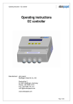
Operating instructions
for built-in fans with size 110 and 138 motors
The device type, date of manufacture (calendar week/year) and the conformity sign
are located on the nameplate on the fan.
For questions about the fan or the delivery of spare parts, please provide the entire
content of the nameplate.
ebm-papst Mulfingen GmbH & Co. KG
Bachmühle 2
D-74673 Mulfingen, Germany
Tel.: +49-7938-81-0
Fax: +49-7938-81-110
[email protected]
www.ebmpapst.com
Please read these operating instructions carefully before starting to work with the
device. Observe the following warnings to prevent malfunctions or danger to persons.
Ensure that the operating instructions are always readily available at the device.
If the device is sold or transferred, the operating instructions must accompany it.
These operating instructions may be duplicated and forwarded for information
about potential dangers and their prevention.
Symbols used
These operating instructions use the following symbols to indicate potentially
hazardous situations and important safety regulations:
Danger!
Indicates a potentially hazardous situation, which, if not avoided,
could constitute a risk for life and limb. Exercise extreme caution
while working.
Revised: 19 September 2007
Version 1.0
Warning!
Indicates a potentially hazardous situation, which, if not avoided, can
result in injuries. Exercise extreme caution while working.
Caution!
Indicates a potentially hazardous situation, which, if not avoided, can
result in minor injuries or property damage.
CONTENTS
1. SAFETY REGULATIONS AND NOTES
2
1.1 Electrical voltage and current
1.2 Safety and protective functions
1.3 Electromagnetic radiation
1.4 Mechanical movement
1.5 Hot surface
1.6 Emission
1.7 Transport
1.8 Storage
1.9 Cleaning
1.10 Disposal
2
2
2
2
2
2
3
3
3
3
2. PROPER USE
3
3. TECHNICAL DATA
3
4. CONNECTION AND START-UP
4
4.1
4.2
4.3
4.4
4.5
4.6
4.7
4.8
4
4
4
7
7
7
7
7
Connecting the mechanical system
Connecting the electrical system
Connection in terminal box
Connection via wires from stator bush
Motor protection
Connecting up several devices
Checking the connections
Switching on the device
1. SAFETY REGULATIONS AND NOTES
5. MAINTENANCE, MALFUNCTIONS, POSSIBLE CAUSES AND REMEDIES
7
5.1 Safety examination
7
Attention!
Indicates a potentially harmful situation, which, if not avoided, can
result in property damage.
Staff qualification
Only specialised electrical personnel may install the device, perform the test run
and work on electrical system.
Only trained and authorised specialist personnel are permitted to transport, unpack,
assemble, operate or maintain the device, or to use it in any other manner.
Basic safety rules
Observe the following when working with the unit:
Warning!
Rotating fan
Long hair, dangling items of clothing and jewellery could become
entangled and be pulled into the device. You could be injured.
➜ Do not wear any loose clothing or jewellery while working on
moving parts. Protect long hair with a hood.
– Do not make any modifications, additions or conversions to the device without
the approval of ebm-papst.
1
1.1 Electrical voltage and current
1.7 Transport
Check the electrical equipment of the device at regular intervals. Remove loose
connections and defective cables immediately.
Caution!
Transport of fan
Cutting and crushing hazard
➜ Wear safety shoes and cut-resistant safety gloves. Transport the
fan in its original packaging only. The vibration values listed in the
technical data must not be exceeded during the entire transport.
Secure the fan so that it does not slip, for example using a lashing
strap.
1.2 Safety and protective functions
Danger!
Missing safety device and non-functioning protective features
Risk of fatal injury
➜ Shut down the device immediately if you detect a missing or ineffective protective feature. The device is an installation item that has
no function on its own. As the operator, you are responsible for ensuring that the device is adequately secured.
1.3 Electromagnetic radiation
Interference from electromagnetic radiation is possible, e.g. in conjunction with
open and closed-loop control devices.
If unacceptable emission intensities occur when the fan is installed, suitable shielding measures must be taken before the device is commissioned.
1.4 Mechanical movement
Danger!
Rotating fan
Body parts that come into contact with the fan while it is rotating
can be injured.
➜ Secure the fan to prevent contact. Before working on the installation/machine, wait until all parts have come to a standstill.
Warning!
Ejected parts in the exhaust zone
Danger of injury
In the event of a fault, balancing weights or broken fan blades may
be ejected.
➜ Take appropriate safety measures. Do not stay in the exhaust
zone.
Caution!
Self-starting fan
Danger of injury
The motor automatically restarts when voltage is applied, for example after a power failure an.
➜ Do not stay in the danger area of the fan. When working on the
fan, switch off the mains supply voltage and secure it from being
switched on again.
1.5 Hot surface
Caution!
High temperature at the motor housing
Danger of burn injuries
➜ Ensure that sufficient protection against accidental contact is
provided.
1.6 Emission
Warning!
Depending on the installation and operating conditions, a sound
pressure level greater than 70 dB(A) can arise.
Danger of noise-induced hearing loss
➜ Take appropriate technical safety measures. Safeguard the operating personnel with appropriate protection measures, e.g. ear protectors.
2
1.8 Storage
Store the device in a dry place, where it is protected in a clean environment. Keep
to the specified storage temperatures, please refer to Chapter 3, Technical data.
If the device is shut down for some time, you are advised to run the device once a
month for about 15 minutes to move the bearings.
1.9 Cleaning
Attention!
Damage to the device during cleaning.
Malfunction possible
➜ Do not clean the device using a water jet or high-pressure washer. Do not use any cleaners containing acids, bases or solvents.
1.10 Disposal
When disposing of the device, please comply with all relevant requirements and
regulations applicable in your country.
2. PROPER USE
4. CONNECTION AND START-UP
The device is designed exclusively as built-in fan for moving air according to the
technical data.
Any other or secondary use is deemed improper use and a misuse of the device.
Installations necessary on the part of the commissioning party must meet the
mechanical, thermal and service life-related stresses that can occur.
4.1 Connecting the mechanical system
Install the device according to your application.
Use the device according to its moisture class.
Caution!
Proper use also includes:
– Operating the device with all protective features.
– Observing the operating instructions.
– Use of the device in accordance with the permissible ambient temperature,
see Chapter 3 "Technical data".
Cutting and crushing hazard when removing the fan from the
packaging
➜ Carefully lift the device out of the packing at using inside area of
the blades (axial fan) or the impeller (radial fan). Be certain to avoid
any shock. Wear safety shoes and cut-resistant safety gloves.
Two people should lift the device out of its packaging if it is heavier
than 10 kg.
Improper use
In particular, the following uses of the fan are prohibited and can lead to dangerous
situations:
–
–
–
–
–
–
–
–
–
Moving air that contains abrasive particles.
Moving highly corrosive air.
Moving air that contains dust pollution, e.g. suctioning off saw shavings.
Using the fan to move flammable gases/particles.
Operating the fan in the vicinity of flammable materials or components.
Operating the fan in an explosive atmosphere.
Using the fan as a safety component or for taking on safety-related functions.
Operation in medical equipment with a life-sustaining or lifesaving function.
Operation in non-stationary installations such as railroad vehicles, aircraft and
spacecraft.
– Operation with completely or partially disassembled or modified protective features.
– Operation with external vibrations that exceed the permissible vibration load.
– In addition, all application options that are not listed under proper use.
If you have specific questions, contact ebm-papst for support.
3. TECHNICAL DATA
Additional device-specific data are available upon request from ebm-papst.
Hot motor housing
Danger of fire
➜ Ensure that no combustible or flammable materials are located in
the vicinity of the fan.
4.2 Connecting the electrical system
The connection to the electrical system is made after the connection to the mechanical system.
– Before connecting the device, ensure that the mains supply voltage matches
the fan voltage.
– Check whether the data on the nameplate agree with the connection data and
the data of the operating capacitor (single-phase motors only).
– Only use cables that are configured for current according to the type plate.
Danger!
Incorrect insulation
Risk of fatal injury from electric shock
➜ Use only cables that meet the specified installation requirements
for voltage, current, insulation material, load etc.
4.3 Connection in terminal box
(valid for axial fans)
Mounting data
Stripping connecting cables
The following must be observed:
–
–
–
Warning!
Tightening torque of the screwed cable gland: 2.0 Nm
Tightening torque of mounting screws of terminal box cover: 0.8 Nm
Property class of mounting screws: 8.8
Strip the cable just enough so that the screwed cable gland is tight and the terminals are relieved of strain (for tightening torques, refer to Chapter 3 "Technical
data").
Ambient conditions
Permitted ambient
temperature for motor
Transport & storage
Operation
-40 °C to +80 °C
-25 °C...+40 °C (60 °C)
Resistance to vibrations 1 g
(acc. to IEC 60068-2-6)
min. 5 mm
50
0.5 g
(acc. to IEC 60068-2-6)
TW1, TW2
L1, L2, L3, and/or L, N
6
Protective earth
6
60
Figure 1: Recommended stripping lengths
in mm (inside the terminal box)
3
Connecting cables with terminals
Caution!
Electrical voltage
The fan is a built-in component and features no electrically isolating
switch.
➜ Only connect the fan to circuits that can be switched off with an
all-pole separating switch. When working on the fan, you must
switch off the installation/machine in which the fan is installed and
secure it from being switched on again.
No water may penetrate along the cable in the direction of the cable
gland.
The cable must be relieved of strain.
Mounting position of fan: shaft vertical, rotor at bottom
Ensure that the cable is routed in the form of a loop ("water trap" see Figure 5).
– Open the terminal box.
– Open the screwed cable gland.
Axial fans with size 110 motors
Axial fans with size 138 motors
are supplied with a sealing cap and
insert for cables with
Ø 6 - 12 mm, see Fig. 2.
are supplied with a sealing cap and
insert for cables with
Ø 7 - 14 mm, see Fig. 2.
– Remove the cap, see figure 3.
– Guide the cable through the cable gland
Figure 5: Fan installed lying flat (shaft
vertical, rotor on bottom), cable routed
as "water trap"
Mounting position: shaft horizontal
When routing cables, ensure that the screwed cable glands are
arranged at the bottom, see Figure 6. The cables must always be
routed downwards.
Figure 2.
Screwed cable gland with cap
Figure 3.
Cap removed
180°
– Connect up the protective earth (PE) wire.
– Connect the remaining leads to the respective terminals.
See Fig. 4.
– Connect up the thermal overload protector (T.O.P.) an.
During the connection work, ensure that no cables splice off.
180°
Figure 6: Cable routing for upright built-in fans (shaft horizontal)
Interface diagram - single-phase capacitor motor
C
Figure 4: Connecting the wires to terminals
The terminal strip is equipped with a penetration prevention device.
– Insert the strands until they meet resistance.
There must be no voltage applied between the terminal and the cable gland. The
cable must be relieved of strain.
Terminal area
single-strand up to 4 mm²
fine-strand
up to 2.5 mm²
4
U1 = blue
U2 = black
U1 Z U2
L
TW TW
N PE
Fig. 7: Single-phase capacitor motor
with thermal overload protector
Z=
brown
PE = green/yellow
TW = grey
Interface diagram - three-phase motor
4.4 Connection via wires from stator bush
(valid for centrifugal fans)
U1 V1 W1 W2 U2 V2 TW TW
L1 L2 L3
U1 = black
PE
Fig. 8: Star connection with thermal overload
protector
U2 = green
V1 = blue
V2 = white
W1 = brown
Motor size
Cable length*
110
800 mm
138
1000 mm
Connect up the wires according to your application.
Stripping connecting cables*
TOP1, TOP2
W2 = yellow
Wires (L1, L2, L3, and L, N)
PE = green/yellow
U1 V1 W1 W2 U2 V2 TW TW
Protective earth
L1 L2 L3
PE
6
85
Fig. 9: Delta connection with thermal overload
protector
With single-phase motors, make sure that the capacitors are also
connected.
Reverse direction of rotation by interchanging two phases.
4.5 Motor protection
Interface diagram - single-phase capacitor motor
N
PE
L
C
TOP
U2 Z
U1
U1 =
U2 =
Z=
PE =
TW =
blue
black
brown
green/yellow
grey
Interface diagram - three-phase motor
L1
U1
L2
V1
L3
Danger!
Lack of motor protection
The motor becomes hot. Body parts that come into contact with the
motor can be injured.
➜ Connect up the thermal overload protector installed in the coil.
Wire the freed thermal overload protectors in the control current circuit so that no automatic switch-on can occur after cooling down
following a malfunction.
Fig. 10: Single-phase capacitor
motor with thermal overload
protector
PE
The motors are equipped with thermal overload protectors to protect the devices.
Check to make sure that the thermal overload protector is correctly connected
before each operation. Failure to correctly connect up the thermal overload protector will invalidate defect warranty cover.
TOP
W1
U1 = black
U2
V2
U2 = green
W2
Fig. 11: Star connection with thermal overload protector
L1
PE
L2
L3
TOP
V1 = blue
V2 = white
W1 = brown
V1
U2
V2
W1
W2
Fig. 12: Delta connection with thermal overload protector.
Reverse direction of rotation by interchanging two phases
Fig 14: Interface diagram motor protecting switch,
single-phase
W2 = yellow
PE = green/yellow
U1
Fig 13: Interface diagram motor protecting switch,
three-phase
Attention!
Lack of motor protection
The motor becomes too hot and thus suffers damage. The motor is
not switched on automatically.
➜ Locate the source of the error and eliminate the error. Connect up
the thermal overload protector installed in the coil.
Voltage control
With open loop speed control using transformers or electronic voltage regulators (e.g. phase control), excessive current may occur.
In addition, noises can occur with phase control, depending on the
manner in which the device is installed.
* Customer-specific differences possible
5
Frequency inverter
Fit sinusoidal filters that work on all poles (live-live and live-earth)
between the frequency inverter and the motor for operation with frequency inverters.
4.6 Connecting up several devices
5. MAINTENANCE, MALFUNCTIONS, POSSIBLE CAUSES AND
REMEDIES
Malfunction/error
Possible cause
Possible remedy
Motor does not
turn
Mechanical blockage
Switch off, de-energise, and
remove mechanical blockage
Mains supply voltage
faulty
Check mains supply voltage,
restore power supply
If you intend to connect up more than one device, you may use the second screw
hole on the terminal box to route another wire.
Faulty connection
Correct connection, see connection configuration
Thermal overload protec- Allow engine to cool off, locate
tor responded
and rectify cause of error, if
necessary cancel switch-on
inhibitor
Warning!
Electric voltage on cable gland
Electric shock
➜ Do not use plastic terminal boxes with metal cable glands.
– Screw the cable gland (size M20) into the pre-cut thread a spanner. Note the
specified tightening torques, please refer to Chapter 3 , Technical data.
– Remove the plastic tab that has become lose when the wire is pressed through
into the terminal box.
Overtemperature of Ambient temperature too
motor
high
If possible, reduce ambient
temperature
Insufficient cooling
Improve cooling
Unacceptable operating
point
Examine operating point,
e.g. reduce throttle resistance
on axial fan
If you have any other problems, contact ebm-papst.
5.1 Safety examination
When connecting, note Chapter 4.2, Connecting the electrical system and Chapter
4.3, Connection in terminal box.
4.7 Checking the connections
How to test?
Frequency
Contact prevention clothing
Visual inspection
at least every 6 months
Fan for damage
Visual inspection
at least every 6 months
Danger!
Mounting of fan
Visual inspection
at least every 6 months
Electric voltage on the device
Electric shock
➜ Always install an earth wire. Check the protective earth.
Mounting of connecting cables
Visual inspection
at least every 6 months
Mounting of protective earth
connection
Visual inspection
at least every 6 months
Insulation of the cables
Visual inspection
at least every 6 months
Tightness of screwed cable
gland (only with connection via
terminal box)
Visual inspection
at least every 6 months
Condensate discharge hole
against blockage
Visual inspection
at least every 6 months
Make sure the power is off.
Secure it from being switched on again.
–
–
–
–
Check the correct fit of the connecting cables.
Fasten the screwed cable gland again.
Ensure that the cable gland is securely tightened.
Tighten the cable gland enough to ensure that water cannot ingress. Refer to
Chapter 3, "Mounting data" section, for the maximum tightening torque
– Fasten the terminal box again.
Refer to Chapter 3, "Mounting data" section, for the maximum tightening torque
Make sure that the terminal box is correctly closed and sealed after completing the
work and that all screws are properly tightened.
Residual current operated device
Only universal (type B) RCD protective devices are permitted. Like
frequency inverters, RCD protective devices cannot provide personal
safety while operating the device.
4.8 Switching on the device
Inspect the device for visible external damage and the proper function of the protective features before switching it on.
6
What has to be tested?