1
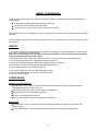
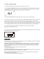
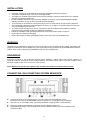
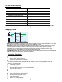
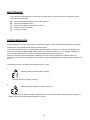
Installation and Operating Instructions
MPPT Solar System Controller
ISC3042
ABOUT THIS MANUAL
These operating instructions come with the product and should be kept with it as a reference to all user’s
of the product.
Read these operating instructions carefully before use,
Keep them over the entire life of the product,
And pass then on to any future owner or user of this product.
This manual describes the installation, function, operation and maintenance of the solar system controller
ISC3042.
These operating instructions are intended for end customers. A technical expert must be consulted in cases
of uncertainty.
SAFETY
1. The solar controller may only be used in PV systems for charging Lead-Acid type batteries. This includes:
SLA, VRLA, Lead-Calcium, AGM and GEL.
Note; User’s should always refer to battery manufacturer/supplier’s recommended values for battery
charging settings and float voltage setting.
2. No energy source other than a solar panel (PV) may be connected to the solar charge controller.
3. Do not connect any defective or damaged measuring equipment.
4. Follow the general and national safety and accident prevention regulation.
5. Never alter or remove the factory plates and identification labels.
6. Keep children away from PV & Battery systems.
7. Never open the device. (No user serviceable parts inside)
8. One set solar module can connect with one controller only.
9. Never touch bare cables.
OTHER RISKS
Danger of fire and explosion
Do not use the solar charge controller in dusty environments, in the vicinity of solvents or where
inflammable gases and vapors can occur.
No open fires, flames or sparks in the vicinity of the batteries.
Ensure that the room is adequately ventilated.
Check the charging process regularly.
Follow the charging instructions of the battery manufacturer.
Battery acid
Acid splashes on skin or clothing should be immediately treated with soap suds and rinsed with
plenty of water.
If acid splashes into the eyes, immediately rinse with plenty of water. Seek medical advice.
2
Function
The solar system controller is designed to:
Monitor the state of charge of the battery;
Control the charging process,
Control the connection/disconnection of loads,
Make sure solar system works at max’ possible power.
Features
Charging Voltage is user programmable.
Load Terminal switches Positive side.
Manual load switch with automatic re-start .
Night-Light Functions
Set the two timer schedule programmable for street light application
Performs the MPPT algorithm to harvest the maximum power available from the solar panel.
Caution
Users should seek advice if any of the following situations occur:
The solar charge controller does not appear to function at all.
The solar charge controller or connected cables are visibly damaged.
Emission of smoke or fluid penetration.
When parts are loose.
In the event of such an occurrence, If possible and safe to do so immediately disconnect the solar
charge controller from the solar panels and battery and insulate cable conductors.
-------------------------------------------------------------MPPT means "Maximum Power Point Tracking". This refers to the type of advanced electronic circuits
used to harvest Maximum Power from your solar panel(s). The Maximum Power Point of PV system s can
vary depending on the prevalent conditions, such as the temperature and solar irradiation levels. This
controller establishes and Tracks the most efficient operating point of the solar panel enabling it to
deliver the maximum available power to the battery.
Operating the controller
The display shows a variety of system data by symbols and digits. Four buttons control all settings
and display windows.
1. Display and operation
LCD display for controller
information and messages.
Page down button
Manual load switch, or
confirmation button in program
mode (Enter button)
Page up button
Button for switching display
windows or calling up the
settings (Menu button)
3
2. Display window
Change the display windows with the “Menu” button; (e.g. for 12V battery)
1. The default window will show like below, battery voltage/capacity volume
of the battery.
2.
Press “menu” button once to check charging current.
3. Press” menu” button again to display the load current.
4. When the charging current or output current is less than 0.5Amp, the LCD will always show Min A.
When there is no current, it will show 0 Amp.
CHARGING CURRENT (<0.5A)
OUTPUT CURRENT (<0.5A)
4
5. If solar module cannot provide current or the current is less than 1Amp for 5 minutes, the controller
will switch to Night mode and display
in the lower right hand corner.
6. When the unit is in the default display mode, Pressing the ‘enter’ button will turn the load ON or OFF
manually. The arrow/lamp
symbol will be displayed when the load terminal is ON.
3. How to set the system time.
1. At default display mode, press “menu” button 3 times to show controller’s system time to you.
In this mode, press “enter” button once, the ‘hours’ will flash, you can adjust the figure via Pageup /
Pagedown button, press “enter” button one more time to confirm the setup for ‘Hour’ and switch to
‘Minute’ setup mode, you can adjust the figure of minute via Page up/Page down button, once it’s done,
press “enter’ button to save.
2. Charging Voltage Check & Program
Press “menu” button 4 times. Window will switch to show BULK voltage setting. To change this setting; Press
“enter” button once, you can program charge voltage via Pageup/Pagedown button:
12V Battery (13.8V-14.8V); 24V Battery (27.6V-29.6V) Press “enter” or “menu” button to save setting.
3. Press “menu” button 5 times. Window will switch to show FLOAT voltage setting. To change this setting;
Press “enter” button once; you can program Float voltage via Pageup/Pagedown button:
12V Battery (13.0V-14.2V); 24V Battery (26.0V-28.4V) Press “enter” or “menu” button to save setting.
4. You can set the FLOAT Voltage to automatically adjust (trim) voltage, based on the ambient temperature: In
the FLOAT setup interface press “enter” button once; use the Pagedown button until LCD displays “OFF”. Float
voltage will vary accordingly to the ambient temperatures stated below:
12V System:
24V System:
≤ 0°C. (14.2-14.4v), 0°C - 20°C (13.8-14.4v), ≥20°C (13.5-14.4v)
≤ 0°C. (28.4-28.8v), 0°C - 20°C (27.8-28.8v), ≥20°C (26.9-28.8v)
5
4. Night-Light Function (NLF) setup.
Press “menu” button 6 times. Window will switch to NLF setup interface. Press “enter” button once, through
Pageup/Pagedown buttons, choose “ON” and then confirm by “enter” button.
After NLF on, press “menu” button, window switch to Timer1 setup interface. Press “enter” button once,
you can adjust the “Hour” (1-12hours) via “Pageup/Pagedown” buttons, and then confirm it by pressing “enter”.
Timer1 hours stands for the time the load terminal will be switched ON.
Press ”menu” button again, window switch to Timer2 setup interface. Press “enter” button once, you can adjust
the “Hour” (1-12hours) via “Page up/Page down” buttons, and then confirm it by pressing "enter”.
Timer2 hours stands for the time the load will be OFF after Timer1 hours have finished.
NOTE: When the Timer2 hours are finished, the load will turn ON again until dawn. (See Diagram below)
If you want the load to stay OFF for the remainder of the night, make sure Timer2 hours are sufficient to reach
dawn.
The ISC3042 recognizes day and night based on the solar array voltage
NLF (Night mode) will start when the PV Input Voltage falls below 10 Volts.
.
Standard Controller Mode = NLF set to OFF, (See Item # 9.1 Page 7)
6
5. Timer1 and Timer2 setup.
To change Timer settings you must first make sure that NLF is set to “OFF”
9.1. Check that NLF (Night light function) is set to “OFF” by pressing the menu (page) button 6 times from
the main default screen. Window will switch to NLF setup interface. Press the “enter” button once, through
Pageup/Pagedown buttons, choose “OFF” and then confirm by “enter” button.
9.2 From the main default screen press the menu button 7 times, Timer1 screen will appear.
9.3 Press the “enter” button once. Then adjust ‘Hour’ via ‘Pageup/Pagedown’ buttons. Press the ‘enter’ button
to confirm the hour setting and switch to ‘Minute’ adjustment. Use ‘Pageup/Pagedown’ buttons to adjust
Minute. Press ‘enter’ button to confirm minute setting. Now using ‘Pageup/Pagedown’ buttons; choose ‘ON’ or
‘OFF’ or ‘ON/OFF’ and then confirm by ‘enter’ button. ‘ON’ stands for the time when you want to turn the load
on. ‘OFF’ stands for the time when you want to turn the load off. ‘ON/OFF’ means the Timer is disabled.
9.4 From the main default screen press the menu button 8 times, Timer2 screen will appear.
Follow step 9.3 operation as per above.
Timer1 and Timer2 setup should now be complete; you can confirm these settings by using the menu key to
scroll through to Timer1 and Timer2 screens
FEATURES
1. PWM Charge control - Depending on the actual battery level, various charging procedures, float charging
and boost charging are automatically performed.
2. Deep discharging protection - If the battery falls below a specified voltage (11.0V/22V), the load output is
disconnected preventing excessive discharge of the battery. Once the voltage increases to 12.0V/24V the
load will be automatically re-connected. The set points of the deep discharging protection are predefined
and cannot be reset.
3. Two timers can be set to turn the loads on and off automatically.
4. Temperature Compensation
ISC3042 has an internal ambient temperature sensor that compensates during the float mode. This functions
only when float voltage setup is set to “OFF” (See item no. 4 page 5)
5. MPPT function - Implementing the latest MPPT technology the controller is able to harness the panels
maximum available output at all times.
6. 5V USB output provides 5Vdc/ 500mA power supplier
7
INSTALLATION
•
•
•
•
•
•
•
•
•
•
Install the controller in a ventilated area away from flammable materials and gases.
The surface should be solid, even, dry and nonflammable.
The battery to controller cable should be as short as possible (1-2mtrs is ideal) and be of a suitable
diameter to minimize voltage loss.
Do not assemble outdoor, the unit should be installed in the way to be protected against humidity,
dripping, rainwater as well as direct and indirect heat (sunlight).
To ensure the air circulation for cooling an area of 15cm on each side of the unit must be kept free.
The LCD display should be protected against UV rays (e.g. sunlight). Long time exposure to UV rays
can permanently discolor the LCD.
The solar charge controller may only be connected to the local loads and the battery by trained
personnel and in accordance with any applicable regulations.
Follow the installation and operating instructions for all components of the PV system.
Ensure that no cables are damaged.
Ensure that polarity of Solar panel/battery/load is correct and use only insulated tools.
WARNING
ISC3042 can work with input voltage up to 65 V DC maximum; when installing at this voltage, particularly with
regard to module open circuit voltage (Voc), the entire solar energy system must be installed with protection
class II. Cover solar modules during installation and use only insulated tools.
GROUNDING
Grounding ISC3042 is not technically required when installing a stand alone solar system. However, if
required, Common grounding of the negative Battery and Load control output is OK (for negative earth
electrical systems such as a caravan or motor-home).
Note: ISC3042 can ground the negative only, and PV array Output should NOT be grounded.
CONNECTING / DIS-CONECTING SYSTEM SEQUENCE
Connect the wires in the sequence from 1 to 6 according the above diagram; when
Disconnect the wires in the REVERSE sequence from 6 to 1 according the above diagram.
Use with 12V or 24V battery bank, (controller will detect voltage of battery automatically).
Never exceed the nominal ratings (see below technical data for reference).
Suggested cable length, 10m solar panel connection cable/2m battery connection cable/5m load
connection cable.
8
TECHNICAL INFORMATION
30A dc
Max. Input Current
65Vdc
Max. Input Open Circuit Voltage (Voc)
30Adc
Max. Load Current
Adjustable Charge Voltage(Bulk)
13.8-14.8V / 27.6V-29.6V
Adjustable Charge Voltage(Float)
13.0-14.2V / 26.0V-28.4V
Low Voltage Disconnect
11.0 / 22.0V dc ±2%
Auto Reconnect Voltage
12.0 / 24.0V dc ±2%
12/24V dc
Output Voltage
<50mA dc
Typical Idle Consumption
-20°C/+50°C
Operating temperature
Remark: ISC3042 is suitable for 12V or 24V system, you can use a 24V solar panel to charge a 12V
battery, but 12V solar panel cannot be used to charge a 24V battery.
Charging Curve
Bulk
Absorption
Float
Bulk: This is the first stage (Constant Current) where the battery is in a low charge state. During this stage
the controller delivers all of the available solar power to the Battery system.
Absorption: In this stage (Constant Voltage) the controller charges at a constant voltage as the amount
of current required to charge the battery is decreasing. The constant voltage regulation prevents
overheating and excessive battery out-gassing; this stage will end when the battery charge current
reduces to below 3 Amps OR after 3 hours of entering absorption mode.
Float (Maintenance): After the battery is fully charged, the controller reduces to a lower Constant Voltage
setting to maintain the Battery (also called trickle charge).
Protection functions
Overcharge protection
Deep discharge protection
Battery under-voltage protection
Solar panel reverse current protection
The following installation faults do not destroy the controller. After correcting fault, the device will
continue to operate correctly:
Overcharge protection
Deep discharge protection
Reverse polarity protection of load, panel and battery
Automatic electronic fuse
Short circuit protection of load and panel
Over voltage protection at panel input
Open circuit protection without battery
Reverse current protection at night
Overload protection
Battery over voltage shutdown
9
MAINTENANCE
The controller is maintenance-free. We strong suggest that all components of the PV system must be
checked at least annually,
Ensure adequate ventilation of the cooling element
Check the cable strain relief
Check that all cable connections are secure
Tighten screws if necessary
Terminal corrosion
ERROR MESSAGES
Caution! Please do not open the controller or attempt to replace components when troubleshooting. Improper
maintenance can be hazardous to the user and the system.
If the controller detects errors or unauthorized operating states, it shows error codes on the display. Error
codes can generally be differentiated, whether there is a temporary malfunction, e.g. regulator overload or a
more serious system error that can be remedied by appropriate external measures.
Since not all errors can be simultaneously displayed, the error with the highest error number (priority) is
displayed. If several errors are present, the second error code is displayed after remedying the more significant
error.
The following meaning is assigned to the different error codes:
1.
Meaning: Battery reverse polarity warning
Remedy: Reconnect battery correctly.
2.
Meaning: Battery Voltage (Too high or too low)
Remedy: Check battery voltage it might be too low or too high, possible recharge battery manually. If
battery can’t be recharged, Replace battery & re-check.
10
3.
Meaning: Module current too high.
Remedy: Reduce the input current (module power) to <30Amps.
4.
Meaning: Over current at the load output.
Remedy:
1) Reduce load current to <30Amps..
2) If reducing load current does not work; Press “Enter” button.
If LCD shows E4 with NO load connected or,
LCD shows current as 0.00A. WITH a load of more than 50Watts running,
Then follow the Reset Procedure as follows;
3) Reset:
Dis-connect the unit by removing all connections in Reverse sequence from 6 to 1 (see Page 8), then
follow the reset procedure:
i. While holding down the “Menu” button, re-connect the Battery terminals to the unit.
ii. Release the “Menu” button, this will prompt the LCD to show “FFFF”
iii. First connect the PV then the Load terminals
NOTE: Always connect the Negative first, then the Positive for all connections
11
The Leading Edge in Solar Technology
:
Waste electrical products should not be disposed of with household waste
Please recycle where facilities exist
Check with your local authority or retailer for recycling advice
Specifications are subject to change without prior notice
Copyright reserved by ProVista Technology Limited
Instruction manual Ver. 2.1
FOR TECHNICAL
ADVICE OR HELP
PLEASE CONTACT:
PH: 07 3219 6655
FAX: 07 3219 6644
EMAIL:[email protected]
WEB: www.electroparts.com.au
12