1
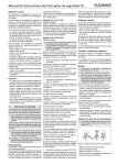
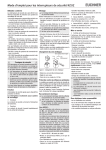
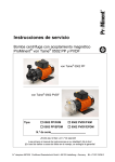
Operating Instructions TP... Safety Switch
Correct use
Safety switches series TP are electromagnetic interlock devices with guard locking.
They interlock movable safety guards so that
dangerous work on machines can only be carried
out if the safety guard is closed and locked.
the safety guard cannot be opened when the
machine is running.
For the control system, this means that
starting commands which cause hazardous situations must become active only when the safety
guard is in protective position and the guard locking is in locked position.
The locked position of the guard locking must be
released only when the hazardous situation is no
longer present.
Before safety switches are used, a risk assessment
must be performed on the machine in accordance
with
EN 954-1, Safety of machinery. Safety related
parts of control systems. General principles for
design, Annex B
EN 1050, Safety of machinery. Principles for risk
assessment
IEC 62061, Safety of machinery - Functional
safety of safety-related electrical, electronic and
programmable electronic control systems.
Correct use includes compliance with the relevant
requirements for installation and operation, in
particular
EN 954-1, Safety of machinery. Safety related
parts of control systems. General principles for
design
EN 1088, Safety of machinery. Interlocking
devices associated with guards. Principles for
design and selection
EN 60 204-1, Safety of machinery. Electrical
equipment of machines. General requirements.
Safety precautions
Safety switches perform a personal protection function.
Incorrect installation or tampering can lead to severe
injuries to personnel.
Safety switches must not be bypassed (bridging
of contacts), turned away, removed or otherwise
rendered ineffective.
The switching operation must only be triggered by
actuators specifically provided for this purpose
which are permanently connected to the safety
guard.
Mounting must be performed only by authorized personnel.
Electrical connection must be performed only
by authorized personnel.
Function
Safety switches series TP permit locking of movable
safety guards.
Position monitoring of the safety guard and monitoring of interlocking are performed via the same
switching element.
Version TP1 and TP3
(mechanically locked)
The guard locking pin is held in locking position by
spring force and released by electromagnetic
actuation. The spring interlock guard locking
functions in accordance with the closed-circuit
current principle. The safety guard cannot be
opened immediately in the event of interruption of
the solenoid power supply.
Versions TP2 and TP4
(solenoid interlock)
This type may be used only in special cases
after strict assessment of the accident risk!
The safety guard can be opened immediately
in the event of interruption of the solenoid
power supply!
The guard locking pin is held in locking position by
electromagnetic force and released by spring force.
The guard locking operates in accordance with the
open-circuit current principle.
Closing and locking
The guard locking pin is released by insertion of
the actuator into the safety switch.
TP1 and TP3: The guard locking pin is moved to
locking position by spring force.
TP2 and TP4: The guard locking pin is moved to
locking position when the solenoid operating
voltage is applied.
The safety contacts are closed.
Unlocking
TP1: The guard locking pin unlocks the actuator /
safety guard to the Open switching position when
voltage is applied to the solenoid (see Figure 2,
column 3).
TP2: The guard locking pin unlocks the actuator /
safety guard to the Open switching position when
voltage is removed from the solenoid (see Figure 2,
column 3).
TP3: The guard locking pin unlocks the actuator /
safety guard to the Unlocked switching position when
voltage is applied to the solenoid (see Figure 2,
column 2).
TP4: The guard locking pin unlocks the actuator /
safety guard to the Unlocked switching position when
voltage is removed from the solenoid (see Figure 2,
column 2).
The safety contacts are opened.
Opening
The guard locking pin is blocked when the actuator
is pulled out. The safety contacts remain positively
opened.
Mechanical release
Changing the actuating direction
Figure 1: Changing the actuating direction
Remove the screws from the actuating head.
Set the required direction.
Tighten the screws with a torque of 0.6 Nm.
Cover the unused actuating slot with the enclosed
slot cover.
Increased overtravel of the actuator is possible
only with the types TP...K... in the case of
vertical approach direction.
Protection against environmental effects
A lasting and correct safety function requires that
the actuating head must be protected against the
penetration of foreign bodies such as swarf, sand,
blasting shot, etc.
Cover the actuating slot, the actuator and the rating
plate during painting work!
Electrical connection
When choosing the insulation material and wire
for the connections, pay attention to the overtemperature in the housing (depending on the
operating conditions)!
The operating voltage for the locking solenoid must match
the value on the rating plate (e.g. US = AC/DC 24 V).
Version TP.. (Cable entry M20x1.5 / Pg 13,5 /
NPT ½")
Break out the required insertion opening.
Fit the cable gland with the appropriate degree
of protection.
For pin assignment see Figure 2.
Tighten the screws with a torque of 0.5 Nm.
Check that the cable entry is sealed.
Close the cover and screw in position.
In the event of malfunctions, the guard locking can
be released with the mechanical release irrespective of the state of the solenoid (see Figure 3).
Unscrew locking screw.
Using a screwdriver, turn the mechanical release
by around 180° in the direction of the arrow.
The mechanical release or the mechanical key release
must be returned to its original position and sealed after
use (for example with sealing lacquer or using wire).
Please observe the supplied dimension drawing in the
case of mechanical key release.
Version TP..SR.. (plug connector)
For pin assignment see Figure 2.
Only switching elements marked with the positive opening symbol
shall be used for the
safety circuit.
For switching elements with four positively
driven contacts only the contacts 21-22 and
41-42 are actuated on locking and unlocking
the guard locking. In applications with potentially hazardous states (e.g. overtravelling movements), contact 21-22 and/or 41-42 must
always be integrated into the safety circuit.“
Mounting
Setup
Assemble the safety switch so that
access to the switch is difficult for operating
personnel when the safety guard is open.
it is possible to operate the mechanical release
and check and replace the safety switch.
Safety switches and actuators must not be
used as an end stop.
Fit an additional stop for the movable part of the
safety guard.
Mount the safety switch only in assembled
condition!
At ambient temperatures greater than 40 °C,
the switch must be protected against contact
with inflammable material or accidental touching.
Insert the actuator in the actuating head.
Mount the safety switch positively.
Permanently connect the actuator to the safety
guard so that it cannot be detached, e.g. using the
enclosed non-removable screws, rivets or welding.
Mechanical function test
The actuator must slide easily into the actuating
head. Close the safety guard several times to check
the function.
Electrical function test
Close safety guard
Activate guard locking
It must not be possible to open the safety guard
Switch on machine
Switch off machine
Deactivate guard locking
It must not be possible to switch on the machine
Open safety guard
End command for deactivating the guard locking
It must not be possible to switch on the machine
Service and inspection
Actuator:
Switching position:
Inserted
Locked
Inserted
Unlocked
v
Removed
Open
h
Type
E1
E1
E2
E2
Pin assignment,
plug connector
E1
E2
SR6
TP1-528..
TP2-528..
TP1-538..
TP2-538..
TP3-537..
TP4-537..
TP1-4131..
TP2-4131..
SR11
No servicing is required, but regular inspection
of the following is necessary to ensure trouble-free
long-term operation:
correct switching function
secure mounting of components
dirt and wear
sealing of cable entry
loose cable connections or plug connectors.
If damage or wear is found, the complete
switch and actuator assembly must be replaced.
Replacement of individual parts or assemblies
is not permitted!
The complete safety switch assembly must be
replaced after 1 million operating cycles.
Exclusion of liability under the following
conditions:
if the unit is not used for its intended purpose
non-compliance with safety regulations
installation and electrical connection not
performed by authorized personnel
failure to perform functional checks.
TP3-4131..
TP4-4131..
Technical Data
TP3-2131..
TP4-2131..
TP3-4121..
TP4-4121..
Ordinal numbers
of switching
elements
TP3-4141..
TP4-4141..
Figure 2: Switching elements and switching functions
Necessary minimum travel + permissible overtravel
Approach direction
Standard actuator
Actuator overtravel
Horizontal (h)
28 + 2
28 + 7
Vertical (v)
29.5 + 1.5
only with TP...K... 29,5 + 7
50
42
3,5
199
v
h
Figure 3a: TP...K...
31
43
3,5
35
v
h
192
for M5 > 35 mm
ISO 1207 (DIN84)
ISO 4762 (DIN 912)
M = 1.5 Nm
144
Mechanical release
M = 0.5 Nm
22
Locking screw
Figure 3b:
TP...A...M20x1,5
TP...A...Pg 13,5
TP...A...NPT½“
16
30
40
M = 0.6 Nm
28
16
42
Parameters
Value
Housing material
Reinforced thermoplastic
Degree of protection according to IEC 60529
Cable entry
IP67
Plug connector
IP65
Mech. life
1x10⁶ operating cycles
Ambient temperature
-20...+55 °C
Degree of contamination
(external, according
3 (industrial)
to EN 60947-1)
Installation position
Any
Approach speed, max.
20 m/min
Actuating force max.
10 N
at 20 °C
Extraction force
20 N
Retention force
10 N
Locking force Fmax
TP1/TP2/TP3/TP4
1300 N
TP5/TP6
800 N
Locking force Fzh in accordance with Test Principles GS-ET-19
F
(FZh = max) = 1000 N
TP1/TP2/TP3/TP4
1.3
TP5/TP6
–
Actuation frequency
7000 / h
Switching principle
Slow-action switching element
Contact material
Silver alloy, gold flashed
Type of connection
TP...
Screw terminal with cable entry
TP...SR6
Plug connector SR6, 6-pin
TP...SR11
Plug connector SR11, 11-pin
Conductor cross-section
0.34 ... 1.5 mm²
(rigid/flexible)
Rated insulation voltage
TP... , TP...SR6
Ui = 250 V
TP...SR11
Ui = 50 V
Rated impulse withstand voltage
TP... , TP...SR6
Uimp = 2.5 kV
TP...SR11
Uimp = 1.5 kV
Switching voltage, min.,
12 V
at 10 mA
Utilization category to EN 60947-5-1
TP... , TP...SR6
AC-15 4 A 230 V / DC-13 4 A 24 V
TP...SR11
AC-15 4 A 50 V / DC-13 4 A 24 V
Switching current, min.,
1 mA
at 24 V
Short circuit protection
4 A gG
according to IEC 60269-1
Conventional thermal current Ith 4 A
Solenoid operating voltage/power input
TP...024
AC/DC 24 V (+10%/-15%) 8 W
TP...110
AC
110 V (+10%/-15%) 10 W
TP...230
AC
230 V (+10%/-15%) 11 W
Duty cycle
100 %
3,5
Figure 3c: TP...SR..
8,5
SR
Figure 3: Dimension drawing
EUCHNER GmbH + Co. KG Kohlhammerstraße 16 D-70771 Leinfelden-Echterdingen Tel. +49/711/75 97-0 Fax +49/711/75 33 16 www.euchner.de
[email protected]
Subject to technical modifications; no responsibility is accepted for the accuracy of this information. © EUCHNER GmbH + Co. KG 084123-08-12/07
Operating Instructions TP... Safety Switch