1
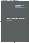
_____________________________________________
OPERATION
& INSTALLATION
MANUAL
________________
VF3000 Series Feeder
_____________________________________________
Web-Tech Australia Pty Ltd
_____________________________________________
Head Office:
11 Electronic Street
EIGHT MILE PLAINS QLD 4113
Phone: +61 7 3841 2844
Fax : +61 7 3841 0005
PO Box 4006
EIGHT MILE PLAINS
BRISBANE QLD 4113
AUSTRALIA
_____________________________________________
Contents
1.0 Mechanical Installation
Page 3
2.0 Electrical Installation
Page 3
3.0 Calibration
Page 4
4.0 Cleaning
Page 5
5.0 Maintenance
Page 6
6.0 Spare Parts Listing
Page 7
Motors
Appendix 1
VF300010 Drawing
Appendix 2
Statement from Managing Director
Appendix 3
2
Note : When testing, cleaning or operating this equipment, ensure that all safe practices are
adhered to. Do not place hands in the area around the metering screw, or agitator (if fitted),
unless the equipment is correctly isolated and tagged out.
Section 1.0 - Mechanical Installation
The model VF3000 Volumetric Feeder is designed to used as a free standing device with or
without an extension hopper, or may be bolted directly to the outlet of a bin. The feeder has
been run at our factory prior to despatch. When installing the feeder, the following guidelines
should be adhered to.
Ensure the base plate is bolted to a flat surface. Do not twist the base plate.
Do not allow loading from other equipment to be supported by the feeder. Large extension
hoppers should be independently supported, not supported by the feeder.
Ensure that there is sufficient space around the feeder for maintenance and cleaning
purposes.
If the feeder is to be bolted directly to the outlet of a bin, ensure that a gasket/sealant is
used between the mounting flanges.
If the feeder is bolted directly to the outlet of a bin, do not connect the baseplate to any
other structure.
Check that all fasteners are tight, and have not vibrated loose in transit.
Ensure that the agitator (if applicable) and metering screw and agitator are tight before
operating.
Ensure that the front access cover hand knobs are tight before operating.
Section 2.0 - Electrical Installation
Ensure that all local regulations regarding electrical installations are adhered to.
2.1 Metering Screw Drive Gearmotor (Fixed Speed)
If the feeder has been supplied as a fixed speed model ie. there is no variable speed
controller, the gearmotor is designed to be connected to a 690 VAC, 3 phase supply. The
motor power is typically 0.75 kW, and motor protection should be provided with the
applicable ratings.
The direction of rotation for the metering screw is anti clockwise when viewed at the
discharge end. Ensure that the motor rotation is correct, and if not, change the phasing of
the motor wiring. Do Not run the feeder for any length of time in the wrong direction , as this
will cause the metering screw to unwind from it’s drive shaft.
3
2.1 Metering Screw Drive Gearmotor (Variable Speed)
If your feeder has been supplied with a variable speed controller, the manufacturers manual
will be added to the end of this manual. Ensure that the manufacturers instructions are
adhered to with regard to the installation and operation of the controller. Ensure that the
current limiting has been correctly programmed into the variable speed drive prior to
operation.
2.2 Agitator Gearmotor (Optional)
If your feeder has been supplied with the optional agitator, the gearmotor is designed to be
connected to a 690 VAC, 3 phase supply. The motor power is typically 1.1kW, and motor
protection should be provided with the applicable ratings.
The direction of rotation for the metering screw is anti clockwise when viewed at the
discharge end. Ensure that the motor rotation is correct, and if not, change the phasing of
the motor wiring. Do Not run the feeder for any length of time in the wrong direction, as this
will cause the agitator to unwind from it’s drive shaft.
3.0 Calibration (Variable Speed Models)
The volumetric feeder has been supplied with a motor speed and metering screw size which
is capable of delivering the required throughput of material based on the specified product
bulk density.
As the actual bulk density of the product form the nominated bulk density, it is advisable to
carry out a series a of tests to determine the output of the feeder at various speeds. To
properly carry this out, you will require the following :
• Container of sufficient size to handle at least 1 minutes running time of material
• Stopwatch
• Check Scale
The tests should be carried out at various rates, usually at 10 % intervals. For example run a
test with the variable speed controller set at 100 %, 90% , 80% etc. When carrying out a test,
set the variable speed controller at the required speed, start the feeder and allow it to
achieve the required speed. Place the container at the end of the discharge tube for exactly
1 minute. Weigh the amount of material obtained and record the results in the following
table.
To determine the output of the feeder in kg/hr, multiply the readings by 60. The throughput of
the feeder can be changed by either changing the screw diameter, or the drive motor.
Contact Web-Tech should you require a different capacity for various applications.
4
Speed (%)
Weight (kg)
10 %
20 %
30 %
40 %
50 %
60 %
70 %
80 %
90 %
100 %
110 %
4.0 Cleaning
***Note: It is essential that the feeder is isolated and tagged out prior to dismantling
the feeder for cleaning purposes.***
The model VF3000 feeder has been designed to allow normal washdowns, however high
pressure hoses should not be aimed directly at the motor(s). Access can be gained to the
inside of the hopper with the following procedure :
• Ensure the feeder is empty.
• Isolate the feeder as per local regulations.
• Remove end caps from bearing housing located at the end of the delivery tube, and then
release bearing from auger shaft.
• Remove the hand knobs from the front cover
• Carefully slide the cover and metering tube off the metering screw, making sure that the
gasket is not damaged.
• To remove the metering screw, wind it in an anticlockwise direction.
• If the feeder is fitted with an agitator, this can also be removed by unwinding
anticlockwise.
• Clean out any build-up in the hopper, particularly in the area where the metering screw
sits, and inside the metering tube.
• Reinstall the metering screw and agitator, ensuring that all threads are clean prior to
installing.
5
• Wipe over the gasket and mating surface of the front cover and reinstall.
• Tigkleen up bearing on auger shaft and replace with covers.
• Ensure all hand knobs are tightened.
• The external surfaces can be cleaned down with a wet rag/sponge, or simply blowing
down with compressed air. Do not use aggressive chemicals for cleaning purposes.
• Remember to remove all isolation tags.
• When the feeder is placed back into service, check for any leaks around the front gasket
area.
5.0 Maintenance
The model VF3000 feeder is designed for minimal maintenance, however like all equipment
it requires some periodic checking. The maintenance should also include regular cleaning.
5.1 Stuffing Box
The VF3000 feeder is fitted with a stuffing box (Item 10) which prevents material leakage
from around the metering screw drive shaft (and agitator drive shaft if fitted). The stuffing box
contains two rows of gland packing with an adjustable compression ring. The area around
the stuffing box should be periodically checked for material leakage. If any leakage is found,
the compression ring (Item 11) should be wound in by tightening the 3 M5 bolts. Ensure that
all bolts are wound by equal amounts, and that the compression ring appears square to the
drive shaft. The adjustment required will be dependant on the wear to the gland packing.
Some materials are obviously more abrasive than others, and therefore the adjustment will
be required more often. If any leaks can not be stopped by adjusting the compression ring,
or the compression ring is fully compressed, the gland packing will require changing. The
gland packing is 8.0 mm square type, and has a Web-Tech P/No. “VF30003605A”. This
image is an example of the gland arrangement , the part number will be the same for the
packing.
6
Gland Packing
5.3 Metering Screw
The metering screw should be periodically checked for excessive wear or damage. If foreign
materials such as tramp metal have passed through the feeder, the metering screw may be
damaged, or can in fact compress. This reduces the volumetric throughput of the feeder. If
the metering screw has been bent, it will rub against the metering tube and may produce a
“metallic” sound when running, particularly when running empty.
5.4 Agitator (Optional)
If an agitator is fitted, it should be checked periodically for wear or damage. Agitator Bearing
P/No W300404440
5.5 Front Cover Gasket
The front cover gasket should be periodically checked for leaks. If the gasket has been
damaged it should be replaced. Replacement gaskets can be ordered from Web-Tech under
P/No. “VF30001801A”.
6.0 Spare Parts
Spare parts can be ordered from Web-Tech using the P/No. as shown on the following
drawing “VF100100”. When ordering any spares, please specify the P/No. and Web-Tech
Contract No. (Shown on front page of this manual).
7
Appendix 1
8