1
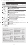
Basic Service Manual APRIL 2011_Layout 1 3/14/11 2:03 PM Page 1
PERISTALTIC METERING PUMPS SINCE 1957
BASIC SERVICE MANUAL
CLASSIC SERIES
Basic Service Manual APRIL 2011_Layout 1 3/8/11 3:34 PM Page 2
Basic Service Manual APRIL 2011_Layout 1 3/8/11 3:17 PM Page 3
CLASSIC SERIES
BASIC SERVICE MANUAL
The Stenner Classic Series peristaltic metering pumps are mechanical
and during their service life will require scheduled maintenance. The
purpose of this manual is to identify the parts that will eventually require
replacement, along with other maintenance basics. Best practice tips and
corrective actions are also covered.
IMPORTANT ICONS USED IN THIS MANUAL
Factory Instructions
Important Information
Additional Information
Basic Service Manual APRIL 2011_Layout 1 3/8/11 3:17 PM Page 4
TABLE OF CONTENTS
SECTION I – GENERAL INFORMATION
SAFETY INFORMATION ................................................................................ 5
TOOL LIST AND CLEANING SUPPLIES .......................................................... 6
CLASSIC SERIES PUMP .............................................................................. 7
SECTION II – INSTALLATION POINTS
INSTALLATION DIAGRAM ............................................................................. 8
VERTICAL INSTALLATION ............................................................................. 9
SUCTION AND DISCHARGE LINES ............................................................. 10
COMPRESSION SEAL ............................................................................... 11
SECTION III – SUBASSEMBLY CONNECTIONS
RIVET AND SLOT IDENTIFICATION .............................................................. 12
SEPARATING SUBASSEMBLIES ................................................................. 13
RECONNECTING FEED RATE TO MOTOR ..................................................... 14
RECONNECTING PUMP HEAD TO FEED RATE ............................................. 15
SECTION IV – PUMP TUBE
PUMP TUBE .............................................................................................. 16
PUMP TUBE BASICS ................................................................................. 17
VISUAL REFERENCE ................................................................................. 18
CONDITIONS THAT REDUCE PUMP TUBE LIFE ...................................... 19-22
PUMP TUBE REMOVAL, REPLACEMENT AND CENTERING ..................... 23-27
IMPORTANT PUMP TUBE INFORMATION .................................................... 28
SECTION V – FEED RATE CONTROL (FRC)
FEED RATE CONTROL ................................................................................ 29
FEED RATE WEAR ................................................................................ 30-31
FEED RATE PARTS REPLACEMENT ....................................................... 32-33
SECTION VI – MOTOR
MOTOR .................................................................................................... 34
CAUSES OF MOTOR MALFUNCTION .......................................................... 35
ROTOR ASSEMBLY REPLACEMENT ............................................................ 36
COIL REPLACEMENT ........................................................................... 37-40
GEARS...................................................................................................... 41
GEAR SET IDENTIFICATION ........................................................................ 42
GEAR WEAR ............................................................................................. 43
GEAR REPLACEMENT ............................................................................... 44
CSM0311
Basic Service Manual APRIL 2011_Layout 1 3/8/11 3:17 PM Page 5
General Information SECTION I
SAFETY INFORMATION
NOTICE: Before installing or servicing the pump, read the pump manual for all
safety information and complete instructions. The pump is designed for
installation and service by properly trained personnel.
HAZARDOUS VOLTAGE:
DISCONNECT power cord before removing motor cover for service. Electrical
service by trained personnel only.
HAZARDOUS PRESSURE/CHEMICAL EXPOSURE
Use caution and bleed off all resident system pressure prior to attempting service
or installation.
Use caution when disconnecting discharge line from pump. Discharge may be
under pressure. Discharge line may contain chemical.
RISK OF CHEMICAL EXPOSURE:
Potential for chemical burns, fire, explosion, personal injury, or property damage.
To reduce risk of exposure, the use of proper personal protective equipment
is mandatory.
BASIC SERVICE MANUAL
5
Basic Service Manual APRIL 2011_Layout 1 3/8/11 3:17 PM Page 6
SECTION I General Information
TOOL LIST AND CLEANING SUPPLIES
• #2 Phillips head screwdriver
• Flat head screwdriver
• 3/8" open end wrench (to change index pin lifter)
• AquaShield®
• Fantastik® or similar (non-citrus) all purpose cleaner
• Needle-nose pliers
• Utility knife
6
www.stenner.com
Basic Service Manual APRIL 2011_Layout 1 3/8/11 3:17 PM Page 7
General Information SECTION I
CLASSIC SERIES METERING PUMP
THREE BASIC SUBASSEMBLIES
MOTOR
FEED RATE CONTROL
(FRC)
PUMP HEAD
Use subassemblies in field for quick replacement.
BASIC SERVICE MANUAL
7
Basic Service Manual APRIL 2011_Layout 1 3/8/11 3:38 PM Page 8
SECTION II Installation Points
INSTALLATION DIAGRAM
Always use rain roof for outdoor
use or if metering pump is
subject to washdowns
Rain roof slides into wall
mounting bracket
(no tools necessary)
On/Off Switch (under
roof, not visible this view)
Grounded Power
Outlet; protected
by Ground-Fault
Circuit-Interrupter
(GFCI)
Vertical Wall Mounting Bracket
(requires 2 screws)
Disassembled View
IN (Suction)
Injection
Check Valve
26-100 psi
Disassembled View
Injection
Fitting
0-25 psi
OUT (Discharge)
Discharge Line
Shut-Off Valve
Suction Line
Injection
Check Valve
Duckbill
Flow direction of solution
Solution Tank
Using pump components
not provided by Stenner can
cause pump to malfunction.
8
www.stenner.com
Basic Service Manual APRIL 2011_Layout 1 3/8/11 3:17 PM Page 9
Installation Points SECTION II
VERTICAL INSTALLATION
Mount the pump vertically and use the spill recovery to drain chemical back to the tank
in the event of tube failure. This will help prevent chemical from collecting in the tube
housing and reduces spillage on the floor.
The pump motor is ventilated and water intrusion can cause motor damage. A rain roof
is recommended for outdoor and wet environments.
Vertical Mount with Rain Roof
Spill Recovery Set-up
Rain roof
(optional) slips
into wall bracket
Spill Recovery
Wall Bracket
Pump Head
Tube drains solution
back to tank
Partial hole is punched through with a
#2 Phillips head screwdriver
Use section of 1/4" suction/discharge
tubing and insert in hole
BASIC SERVICE MANUAL
9
Basic Service Manual APRIL 2011_Layout 1 3/8/11 3:17 PM Page 10
SECTION II Installation Points
SUCTION AND DISCHARGE LINES
The suction line should be 3" from the tank bottom to prevent picking up sediment
which can cause blockage in the check valve, duckbill and discharge line.
Allow slack in both the suction and the discharge lines so the pump tube fittings can
flex. The slack prevents stress on the pump tube and fittings to help reduce the chance
for breakage and leaks.
Suction Line
3.5"
(9 cm)
Weighted
Suction Line
Strainer
3"
The suction line should not be inserted to the bottom of the weighted strainer.
If the suction line becomes flush with the nose of the strainer, the pump may
not prime due to blockage.
Use Stenner suction and discharge tubing, rain roof and UV gray tank for
outdoor applications.
10
www.stenner.com
Basic Service Manual APRIL 2011_Layout 1 3/8/11 3:42 PM Page 11
Installation Points SECTION II
COMPRESSION SEAL
The suction and discharge lines are installed to the pump tube fittings with a compression
type seal consisting of the connecting nut and ferrule. The beveled end of the ferrule
should face the tube fitting and the suction and discharge lines should bottom into the
tube fitting.
Connecting Nut
Ferrule
Discharge Line
Suction Line
Finger tighten
connecting nut.
DO NOT use thread
seal tape on pump
tube threads
DO NOT
use pliers
For 3/8" connections only. While stabilizing the tube fitting, attach female
end of adapter to the tube fitting(s) (ferrule inside). Slide line through 3/8"
connecting nut and finger tighten to male end of adapter. If leak occurs,
gradually tighten the 3/8" connecting nut as required.
BASIC SERVICE MANUAL
11
Basic Service Manual APRIL 2011_Layout 1 3/8/11 3:17 PM Page 12
SECTION III Subassembly Connections
RIVET AND SLOT IDENTIFICATION
Indentation
Motor shaft and
pressure spring coated
with Aquashield®
Rivets (3)
Bump
Mounting Plate
Rivet Slots (3)
Plate Screws (3)
The pressure spring is not used with the fixed output pump.
12
www.stenner.com
Basic Service Manual APRIL 2011_Layout 1 3/8/11 3:17 PM Page 13
Subassembly Connections SECTION III
SEPARATING SUBASSEMBLIES
1.
Turn the pump off and unplug the power cord.
2.
Hold the feed rate control section and turn the pump head clockwise until it stops.
3.
Pull the pump head straight out.
4.
Hold the motor assembly, grasp the feed rate control section and turn clockwise
until it stops, and pull it straight out.
Pump Head
Feed Rate Control
Feed Rate Control
Motor
BASIC SERVICE MANUAL
13
Basic Service Manual APRIL 2011_Layout 1 3/8/11 3:17 PM Page 14
SECTION III Subassembly Connections
RECONNECTING FEED RATE TO MOTOR
1.
Before reconnecting the feed rate control to the motor, confirm pressure spring is in
place and place feed rate control on the shaft.
2.
Turn the feed rate control counterclockwise to line up the flat side of the motor shaft
(d shaft) with the flat side of the brass spider in the feed rate control and push towards
the motor.
3.
Push and turn the feed rate control until the rivets on the gear case are inside the
rivet holes on the feed rate.
4.
Turn counterclockwise until it locks into place and the bump on the feed rate
mounting plate fits into the indentation in the gear case cover.
The arrow on the feed rate control should be on top and confirm the bump is
in the indentation.
14
www.stenner.com
Basic Service Manual APRIL 2011_Layout 1 3/8/11 3:17 PM Page 15
Subassembly Connections SECTION III
RECONNECTING PUMP HEAD TO FEED RATE
1.
Put the pump head with main shaft into the feed rate control and turn it
counterclockwise until the shaft falls into place.
2.
Push the pump head toward the feed rate while turning it counterclockwise. Line up
the rivet holes on the pump head with the rivets on the feed rate control.
3.
Continue to push until the rivets are inside the holes and the snap lock engages.
4.
Turn the pump head counterclockwise to secure the rivets in the rivet slots, firmly
attaching the pump head.
Motor
Feed Rate Control
Arrow
Pump Head
Illustration shows proper orientation of the pump head.
BASIC SERVICE MANUAL
15
Basic Service Manual APRIL 2011_Layout 1 3/8/11 3:51 PM Page 16
SECTION IV Pump Tube
PUMP TUBE
Fluid is forced along by waves of contraction produced mechanically on flexible tubing.
The tube is squeezed by two of the three rollers that move along the tube. As the roller
moves, the compressed section generates a vacuum, creating a self-priming function. The
remaining two rollers repeat the process and the rotation creates a pumping action that
results in both suction lift and outlet pressure.
Rollers
Discharge
Suction
16
www.stenner.com
Basic Service Manual APRIL 2011_Layout 1 3/8/11 3:17 PM Page 17
Pump Tube SECTION IV
PUMP TUBE BASICS
The tube is the workhorse of the pump. It is perishable and will eventually stop functioning
from natural wear or when it reaches the end of its service life. Indications of the end of
service life are:
• Tube leaks
• Tube is fatigued causing a reduction or lack of output
The pump tube service life can be reduced by conditions of the application
or the installation. These conditions are:
• Calcium or mineral deposits
• Sediment blockages
• Chemical incompatibility
• Corrosion
• Improper handling
PUMP TUBE PRESSURE RATING
*
PUMP TUBE
0-25 psi (0-1.7 bar)
#1
#2
#3
#4
#5
#7*
✔
✔
✔
✔
✔
26-100 psi (1.8-6.9 bar)
Check valve required
✔
✔
✔
Classic Single Head ONLY
Tube number located on fitting
For maximum pump tube life, always identify the reasons for the failure and
correct the problem before a new tube is installed.
BASIC SERVICE MANUAL
17
Basic Service Manual APRIL 2011_Layout 1 3/8/11 3:17 PM Page 18
SECTION IV Pump Tube
VISUAL REFERENCE
A diamond pattern that forms where the tube presses against the tube housing indicates
excessive back pressure. Excessive back pressure can be caused by any blockage, a
clogged duckbill or when the system pressure exceeds the pump tube pressure rating.
An oval pattern indicates worn rollers and/or the pump tube has reached the end of its
service life. Pump tubes can rupture without either pattern apparent.
Tube
Roller
DIAMOND PATTERN
TEAR DROP PATTERN
OVAL PATTERN
Excessive pressure
or blockage
Normal
Fatigued tube or
worn components
(rollers)
The most common tube problems are from a lack of routine maintenance.
Always establish an application specific maintenance schedule.
18
www.stenner.com
Basic Service Manual APRIL 2011_Layout 1 3/8/11 3:17 PM Page 19
Pump Tube SECTION IV
CONDITIONS THAT REDUCE TUBE LIFE
IMPROPER TUBE HANDLING
• Not following factory tube replacement instructions.
• Storing tubes in high ambient temperatures or long term exposure to direct sunlight
weakens tube material.
• Prior to installation, pre-stretching, lubricating the tube and/or roller assembly or
pinching during installation, compromises the tube material.
• Excessive pulling of the tube fitting, during installation, can result in compromising the
material. Allow the rollers to stretch tube into position according to the tube
replacement instructions.
• Using pliers to center or secure connections can damage ferrules. The connecting nut
must be finger tightened only.
• Using thread seal tape prevents ferrules from seating properly into tube fitting and
can cause leaks.
• Not allowing enough slack in the suction and discharge lines so the tube fittings can
flex puts stress on the tube and fittings.
DO NOT use thread seal tape or pliers on pump tube threads.
BASIC SERVICE MANUAL
19
Basic Service Manual APRIL 2011_Layout 1 3/8/11 3:17 PM Page 20
SECTION IV Pump Tube
CONDITIONS THAT REDUCE TUBE LIFE continued
CRACKED PUMP HEAD
The tube housing can crack from wear, over tightening cover screws and long term
chemical exposure due to incompatibility with the housing material (refer to Chemical
Resistance Guide).
SEIZED ROLLERS IN THE ROLLER ASSEMBLY
Corrosive chemicals that collect on the roller bushings, as a result of atmosphere or tube
failure, can result in seizing the rollers.
Corrective Action
1. Confirm chemical compatibility with housing and pump tube material.
2. Review factory recommended vertical pump installation.
3. In the event of tube rupture, rinse the chemical residue from the housing and
roller asembly with factory recommended cleaners.
4. If tube housing is cracked, replace.
Confirm rollers turn freely
Normal roller wear can cause a lack of output as a result of the rollers’
inability to fully squeeze the tube.
20
www.stenner.com
Basic Service Manual APRIL 2011_Layout 1 3/8/11 3:53 PM Page 21
Pump Tube SECTION IV
CONDITIONS THAT REDUCE TUBE LIFE continued
EXCESSIVE BACK PRESSURE AT THE POINT OF INJECTION
Calcium or mineral deposits in the injection fitting section of the check valve can cause
blockage or restriction creating back pressure that exceeds the pump tube pressure rating.
Corrective Action
1. Insert a round shank screwdriver through injection fitting into the pipe to locate or
break up accumulated deposits. If screwdriver can’t be inserted, drill the deposit
out of the injection fitting. Do not drill through the opposite pipe wall.
2. Replace duckbill.
Injection Check Valve
Duckbill
Areas that clog
Replace duckbill
Clean out accumulated deposits
with a #2 phillips head screw driver
EXCESSIVE BACK PRESSURE AT THE POINT OF INJECTION
Insoluble sediments or particulates drawn through the suction line from the bottom of
the tank can cause blockage or restriction in the check valve duckbill. These solids and
excessive pressure can damage the pump tube.
Corrective Action
1. Replace suction and discharge tubing and clean sediment from tank bottom.
2. Position weighted strainer 3" from tank bottom.
3. Replace duckbill.
At every tube change, trim approximately 1" off the end of both the suction
and discharge lines before installing new ferrules. Replace duckbill (26-100
psi applications) and ferrules with every new tube.
BASIC SERVICE MANUAL
21
Basic Service Manual APRIL 2011_Layout 1 3/8/11 4:00 PM Page 22
SECTION IV Pump Tube
CONDITIONS THAT REDUCE TUBE LIFE continued
SPLIT ALONG SIDE OF THE TUBE
The tube rubbing against the edge of the tube housing can cause the side to split.
Corrective Action
Always follow the factory’s tube replacement instructions which include centering the
tube on the rollers.
Rollers
Tube off center
on rollers
Cover Plate
The tube will not center if it twists during installation or if the rollers are worn.
Refer to the Trouble Shooting guide in the Classic Series Installation Manual
for more pump tube and pump head conditions and solutions.
22
www.stenner.com
Basic Service Manual APRIL 2011_Layout 1 3/8/11 3:17 PM Page 23
Pump Tube SECTION IV
REMOVE TUBE
1.
Confirm pump is off. Remove and set aside cover and screws.
2.
Set feed rate dial on setting L or 1.
3.
Turn pump on and let it run until one of three roller assembly slots lines up with the
tube fitting on the suction side.
4.
Turn pump off.
5.
Lift tube fitting out of housing slot and pull it toward center of roller assembly.
6.
Turn pump on and allow roller assembly to jog while guiding tube, with tension, up
and out of housing.
7.
Turn pump off. Remove and discard pump tube.
Slots
Pull out
Hold tube toward center
Prior to tube removal, pump water through tube to remove chemical.
BASIC SERVICE MANUAL
23
Basic Service Manual APRIL 2011_Layout 1 3/8/11 3:17 PM Page 24
SECTION IV Pump Tube
REMOVE TUBE continued
8.
Remove roller assembly, shaft, and housing.
9.
Use non-citrus all-purpose cleaner to clean chemical residue from pump head
housing, roller assembly and cover.
10. Check housing for cracks. Replace if cracked.
11. Ensure rollers turn freely. Replace roller assembly if the rollers are seized or worn or
if there is a reduction or lack of output from the pump.
12. Reinstall clean tube housing. On an adjustable pump, install the shaft.
13. Apply AquaShield® to the shaft tip.
14. Install roller assembly.
Confirm rollers turn freely
DO NOT lubricate pump tube or roller assembly.
24
www.stenner.com
Basic Service Manual APRIL 2011_Layout 1 3/8/11 3:18 PM Page 25
Pump Tube SECTION IV
INSTALL TUBE
1.
Confirm the pump is off. Manually rotate the roller assembly counterclockwise to
align one of three roller assembly slots with the suction side housing slot.
2.
Place tube fitting into suction side slot of the housing and the roller assembly slot.
3.
With pump setting on L, hold tube fitting and jog roller assembly by turning the
pump on.
IMPORTANT! Avoid rotating wrist, which can result in a twisted tube that will not center.
DO NOT force tube and be careful of your fingers.
4.
Guide tube with slight tension toward the center to prevent pinching between
housing and roller assembly. If the tube is pinched during installation, discard.
Suction Tube
Housing Slot
Guide with slight tension
Roller Assembly Slot
Turn the pump on. Walk tube in
Identify the cause of tube failure prior to installing a new tube.
A used tube will have stretched approximately 3/4" and the new tube will
appear to be stiff and short. Follow directions to allow rollers to stretch tube
into place.
BASIC SERVICE MANUAL
25
Basic Service Manual APRIL 2011_Layout 1 3/8/11 3:18 PM Page 26
SECTION IV Pump Tube
INSTALL TUBE continued
5.
When tube reaches the discharge tube housing slot, turn pump off.
6.
Turn dial ring to setting 10, hold tube fitting firmly, do not pull, and turn pump on.
7.
Allow rollers to stretch tube into place while guiding tube into slot.
8.
Turn pump off.
9.
Apply a small amount of AquaShield® to cover bushing ONLY and replace cover and
two screws. Leave the front screw between the fittings loose for centering the tube
in the next step.
Guide
Discharge Tube
Housing Slot
Roller Assembly Slot
Apply AquaShield® to cover bushing
Cover screws are self-tapping and must be backed in to locate original
threads before securing. If a screw boss is stripped, use alternate bosses and
position opposite from each other. Never secure the cover plate with more
than 2 screws.
26
www.stenner.com
Basic Service Manual APRIL 2011_Layout 1 3/8/11 4:37 PM Page 27
Pump Tube SECTION IV
CENTER TUBE
1.
To center pump tube on rollers, set feed rate dial to setting 10. Turn pump on.
2.
Turn the tube fitting on the suction side not more than 1/8 of a turn in the direction
tube must move.
3.
DO NOT let go of fitting until tube rides approximately in center of rollers.
4.
Turn pump off, let go of fitting, and finger tighten cover screws.
5.
Inspect the suction and discharge lines, point of injection, and check valve duckbill
for blockages. Clean and/or replace as required.
6.
Reconnect the suction and discharge lines.
1/8 turn
Leave the screw loose
TUBE CHANGE FOR FIXED OUTPUT PUMP
To install a new tube in a fixed output pump, follow the instructions
for the adjustable pump and utilize the on/off switch to jog the
roller assembly in the absence of the feed rate control.
At every tube change, trim approximately 1" off the
end of both the suction and discharge lines before
installing new ferrules. Replace duckbill (26-100
psi applications) and ferrules with every new tube.
BASIC SERVICE MANUAL
27
Basic Service Manual APRIL 2011_Layout 1 3/8/11 3:18 PM Page 28
SECTION IV Pump Tube
IMPORTANT TUBE INFORMATION
• Always follow factory tube replacement and centering instructions.
• Schedule a tube replacement at regular intervals according to the needs of the
specific application.
• A used tube will have stretched approximately 3/4" and the new tube will appear to
be stiff and short. Follow directions to allow rollers to stretch tube into place.
• Replace ferrules with every tube change, ferrules are the seal between the tube fitting
and the connecting nut.
• Only finger tighten the connecting nut. Hold the tube fitting when tightening to prevent
breaking the internal seal and the fitting from spinning inside the tube.
• For 26-100 psi applications, inspecting and replacing the duckbill at every tube
change is recommended.
• Santoprene® pump tubes are not compatible with petroleum or oil-based products.
Refer to the chemical resistance chart for compatibility or call the factory.
For maximum tube life, always identify the reasons for the failure and correct
the problem before a new tube is installed.
28
www.stenner.com
Basic Service Manual APRIL 2011_Layout 1 3/8/11 3:18 PM Page 29
Feed Rate Control SECTION V
FEED RATE CONTROL (FRC)
The feed rate control adjusts the output by utilizing a cam and spring loaded lifter system
to control the rotation of the roller assembly according to the setting on the dial ring.
Inside the FRC is a brass spider assembly that consists of a pin with carbide tip and
spring inside the holder attached to a lifter.
When the pump is on, the spider assembly rotates.When the lifter drops into the FRC
channel, the pin engages the index plate rotating the roller assembly creating the pumping
action.
When the lifter rides on the cam, the pin is lifted inside the holder. The roller assembly
does not rotate, resulting in no pumping action.
FRC Channel
Feed Rate Control
Cam
Index Plate
Brass Spider Assembly
Lifter, holder, and index pin
spring is enclosed
Index pin retracts when lifted.
BASIC SERVICE MANUAL
29
Basic Service Manual APRIL 2011_Layout 1 3/8/11 3:18 PM Page 30
SECTION V Feed Rate Control
FEED RATE CONTROL WEAR
Indication of wear is apparent when the feed rate control makes a skipping or ratcheting
sound. The pump output is less than the desired setting.
Worn groove in
plastic cam
GROOVE IN CAM
More cam is exposed to the rotation of the
lifter at lower dial ring settings leading to
cam wear and causing index malfunctioning.
Higher settings will reduce cam wear.
Inspect and replace cam as needed.
WORN LIFTER
If the lifter arm wears and flattens it may
not fully lift the pin out of the index plate.
The pin will make a ratcheting sound from
dragging across the plate. The feed rate
control will index inconsistently at different
settings. Replace the lifter as needed.
Flat area
Should look like this
WORN INDEX PLATE
A worn cam or lifter can cause the index
pin to drag across the index plate and
elongate the holes. The pin will skip across
the holes and cause index malfunction.
The plate can be flipped to use the other
side, or it may be replaced. Remember to
grease with AquaShield®.
Index plate with elongated holes
Corrective Action
To reduce wear on the feed rate parts,
specify the pump closest to its
maximum output capacity within the
needs of the application. Check the
lifter, cam and index plate during scheduled maintenance.
30
www.stenner.com
Basic Service Manual APRIL 2011_Layout 1 3/8/11 3:18 PM Page 31
Feed Rate Control SECTION V
FEED RATE CONTROL WEAR continued
SEIZED INDEX PIN AND/OR LIFTER ASSEMBLY
Water or chemical intrusion will corrode the pin and lifter causing them to seize; the
feed rate will malfunction.
Corrective Action
1. Replace the index pin and/or lifter assembly as needed.
2. Review the factory recommended vertical installation.
3. Schedule a pump tube replacement at regular intervals according to the specific
application. For 26-100 psi applications replace the duckbill at every tube change.
BASIC SERVICE MANUAL
31
Basic Service Manual APRIL 2011_Layout 1 3/8/11 3:18 PM Page 32
SECTION V Feed Rate Control
PARTS REPLACEMENT
1.
Remove and set aside:
• Three screws
• Feed rate mounting plate
• Dial ring (observe installed cam)
• Brass spider assembly
• Index plate
2.
If required, remove index pin assembly by unscrewing with a 3/8" wrench and replace.
3.
Flip worn index plate over OR install new index plate.
4.
Clean out FRC channel before installing new cam.
5.
Apply AquaShield® to lubricate the cam’s angled tip.
6.
To install the cam, feed the angled cam tip into the FRC channel and keep the 90º
end in the up position. Place thumb over the cam to guide as it is inserted in the
channel.
7.
Continue to feed the cam in the channel until there is approximately a 1/2" gap
between the cam tip and the beginning of the channel.
Angled tip
3/8" wrench
Angled end
Installing New Cam
90º end
90º angle
32
www.stenner.com
Basic Service Manual APRIL 2011_Layout 1 3/8/11 3:18 PM Page 33
Feed Rate Control SECTION V
PARTS REPLACEMENT continued
8.
Apply Aquashield® to the inside of the dial ring for easier turning.
9.
Place dial ring boss onto the cam’s 90° end.
10. While keeping the 90° end in the boss and the cam in the FRC channel, in a
clockwise motion, place the dial ring onto the FRC housing and snap into place.
11. Apply AquaShield® to bottom of the FRC housing before placing index plate inside.
Apply AquaShield® to the top of the index plate.
12. Place the spider assembly on the index plate. The lifter tip should be positioned in
the 1/2" gap in the FRC channel.
13. To secure mounting plate, align its arrow with the FRC housing arrow and install the
three screws.
If the dial ring does not rotate from L to 10, the FRC mounting plate is in the
wrong orientation.
The dial ring will be stiff or difficult to rotate if it lacks AquaShield® or the
screws are over tightened. If the screws are too loose, the dial ring can
inadvertently be turned to setting 10 by the motor.
BASIC SERVICE MANUAL
33
Basic Service Manual APRIL 2011_Layout 1 3/8/11 3:18 PM Page 34
SECTION VI Motor
MOTOR
The motor has a cylindrical rotor with shaft that is encased within a magnetic coil. When
power is applied to the coil, the rotor rotates. The rotor’s directional rotation is determined
by the orientation of the copper shaded poles on the coil. The helical end of the rotor
engages the series of gears in the gear case.
Rotor Assembly
Coil
Helical End
Gears
34
www.stenner.com
Basic Service Manual APRIL 2011_Layout 1 3/8/11 3:18 PM Page 35
Motor SECTION VI
CAUSES OF MOTOR MALFUNCTION
WATER INTRUSION
The motor is fan cooled and needs proper ventilation while protecting it from water
intrusion.
Corrective Action: Mount the single head pump vertically with pump head downward
and use the rain roof in outdoor installations, in areas subject to wash downs, or in
moist environments.
CHEMICAL VAPORS
The motor won’t be able to rotate freely if the coil, rotor and bearing are rusted or corroded.
Corrective Action:
1. Avoid mounting the pump over an open solution tank.
2. Review vertical installation.
INCORRECT VOLTAGE
The motor voltage must match power supply to avoid a burned coil.
Corrective Action: Use a volt meter for confirmation.
DAMAGED BEARING BRACKETS
Cracked or broken bearing bracket(s) result in rotor mis-alignment that can cause the rotor
to bind to the magnetic coil that may be evident by a humming sound.
Corrective Action:
1. Check the condition of the brackets and phenolic gear.
2. Replace parts as needed.
Refer to the Trouble Shooting guide in the Classic Series Installation Manual
for motor conditions and solutions.
BASIC SERVICE MANUAL
35
Basic Service Manual APRIL 2011_Layout 1 3/8/11 4:05 PM Page 36
SECTION VI Motor
ROTOR ASSEMBLY REPLACEMENT
B
D
F
D
A
C
G
E
A rotor assembly includes B, D & F.
1.
Remove and set aside:
• Two motor housing screws (not shown)
• Motor housing A
• Plastic fan B (discard old fan)
• Two coil screws and lock washers C
• Coil (keep wires connected) E
2.
Remove and discard the rotor F and two amber bearing brackets D.
3.
Press the new amber bearing bracket D onto the threaded brass inserts in the back
of the gear case G.
4.
Install the new rotor F by inserting the shaft (helical gear side) onto the amber
bearing bracket D.
5.
Place the coil E (see Correct Coil
Orientation) over the rotor F onto the
bearing bracket D.
6.
Snap into place the second bearing
bracket onto the rotor.
Copper Rods
7.
Insert two coil screws with lock
washers C and tighten.
Coil
8.
Starting at an angle, press fan B (with
hub side down) onto the rotor shaft.
9.
Reinstall the two motor housing screws
and tighten the self-tapping screws to
secure the motor housing A.
Correct Coil Orientation
Coil Lead Wire
Vent
Opening
36
www.stenner.com
Coil Lead Wire
Basic Service Manual APRIL 2011_Layout 1 3/8/11 5:05 PM Page 37
Motor SECTION VI
COIL REPLACEMENT
1.
Disconnect power to pump.
2.
Remove motor base. Remove two motor cover screws.
3.
Invert the pump and use the pump head and feed rate control as a stand to work
on the motor. See illustration.
4.
Remove fan and set aside.
Motor
Pump Head
Feed Rate Control
Motor Screws
Gear Case Shaft
Rotor
Fan
Coil Screw and Washer
Coil Copper Rods
Motor Cover
Screw Boss
Motor Cover
Amber Bearing Bracket
Motor Cover Screw Boss
Coil
Feed Rate Control
Pump Head
BASIC SERVICE MANUAL
37
Basic Service Manual APRIL 2011_Layout 1 3/8/11 5:06 PM Page 38
SECTION VI Motor
COIL REPLACEMENT continued
5.
Disconnect ground wire (with eyelet) and set screw aside.
6.
Cut the power cord and coil lead wires from motor cover at the wire nut (four cuts
total). Set cover to the side.
7.
Remove and set aside:
• Two coil screws and washers from the rotor bracket
• Plastic amber bearing bracket
8.
Remove coil and discard.
Set Screw
Ground Wire
Eyelet
Ground Wire Screw Boss
Lead Wire
2 Lead Wires
Wire Nuts
(crimp
type)
38
www.stenner.com
Basic Service Manual APRIL 2011_Layout 1 3/8/11 4:08 PM Page 39
Motor SECTION VI
COIL REPLACEMENT continued
9.
Install new coil over rotor on the remaining amber bracket. The correct orientation is
with two copper rods in the upper right corner and the vent opening at the bottom
of the gear case. Place bracket back on the rotor and securely seat into new coil.
Install screws and washers and fasten bracket to coil.
10. With the metal band facing the bracket, press fan flush on rotor shaft.
Rotor
Copper Rods
Amber Bearing Bracket
Coil
Coil Lead Wire
Coil Lead Wire
Vent Opening
BASIC SERVICE MANUAL
39
Basic Service Manual APRIL 2011_Layout 1 3/8/11 3:20 PM Page 40
SECTION VI Motor
COIL REPLACEMENT continued
11. With wire strippers set at 16 gauge, strip approximately 1/2" from the power cord
and on/off switch lead wires in the motor housing.
12. Secure ground wire (with eyelet) to motor coil.
13. Crimp the stripped lead wires to each of the new coil lead wires.
14. Tuck wire nuts into bottom of motor cover and secure cover back in place (before
tightening, reverse cover screws to catch original threads).
15. Apply power to motor and test.
Lead Wire
Ground
Wire
Wire Stripper
Strip Approx, 1/2"
Lead Wire
Ground Wire
40
www.stenner.com
Basic Service Manual APRIL 2011_Layout 1 3/8/11 3:20 PM Page 41
Motor SECTION VI
GEARS
Located in the gear case, the metal reduction gear and phenolic gear control the rpm of
the feed rate and pump head. The 45 and 100 series delivers approximately 26 rpm and
approximately 44 rpm for the 85 and 170 series. The motor shaft with gear drives the
feed rate control.
Motor
Gear Case
Phenolic Gear
Metal
Reduction
Gear
Motor Shaft
with Gear
BASIC SERVICE MANUAL
41
Basic Service Manual APRIL 2011_Layout 1 3/8/11 3:20 PM Page 42
SECTION VI Motor
GEAR SET IDENTIFICATION
The illustrations show the diameters of the gears and pinions.
45 & 100 SERIES GEARS
Phenolic Gear
Metal Reduction Gear
3/8"
9/16"
1 3/8"
1 3/8"
85 & 170 SERIES GEARS
Phenolic Gear
42
www.stenner.com
Metal Reduction Gear
9/16"
9/16"
1 3/8"
1 1/4"
Basic Service Manual APRIL 2011_Layout 1 3/8/11 3:20 PM Page 43
Motor SECTION VI
GEAR WEAR
Generally, gear failure can be caused by misalignment mainly due to the wear over the
service life of the pump.
Check for the following conditions that can contribute to the phenolic gear stripping.
• Water or chemical intrusion
Phenolic Gear
• Cracked bearing bracket
• Worn gear posts
• Worn gear case cover
• Rusted helical gear
• Insufficient lubrication
Teeth missing
Corrective Action:
1. Review the vertical installation that includes using a rain roof in outdoor
applications or wet environments.
2. Replace gears that show visible wear or corrosion.
3. Replace gear posts that are worn, rusted or corroded.
4. Inspect the gear case and cover for cracks or corrosion and replace as needed.
5. Inspect the helical gear at the end of the rotor. Buff off the rotor if rusted or
replace the rotor assembly.
6. Lubricate with AquaShield®.
Apply a generous amount of AquaShield® to gear posts, pinions, gear rings
and the main shaft with gear after doing service in the gear case.
BASIC SERVICE MANUAL
43
Basic Service Manual APRIL 2011_Layout 1 3/8/11 3:20 PM Page 44
SECTION VI Motor
GEAR REPLACEMENT
1.
Remove four Phillips head screws from gear case cover.
2.
Remove gear case cover.
3.
Remove gears and inspect posts. To remove posts, grasp with pliers and pull
straight out.
4.
Wipe away old grease, check for rust or corrosion on the rotor shaft and remove
with wire brush any visible rust or corrosion prior to replacing gears.
5.
Install gear posts by tapping with rubber mallet until bottomed.
6.
Apply AquaShield® on new gear posts before installing gears.
7.
Install phenolic gear and spacer.
8.
Install metal reduction gear and motor shaft with gear.
9.
Use remaining AquaShield® on top of the three gears.
10. Re-attach gear case cover and four new screws, finger tighten the screws. Screws
must be backed in to locate original threads before securing, to prevent stripping
screw boss.
Gear Post Phenolic Gear
Metal Reduction Gear
Pressure Spring
(adjustable models only)
Thrust
Washer
Gear Case
Phenolic
Motor Shaft
Gear
Spacer with Gear
Gear Case Cover
Gear Case
Phenolic Gear
with Spacer
Motor Shaft
with Gear
44
www.stenner.com
Metal Reduction Gear
Basic Service Manual APRIL 2011_Layout 1 3/14/11 2:03 PM Page 45
Basic Service Manual APRIL 2011_Layout 1 3/8/11 4:35 PM Page 46
STENNER PUMP COMPANY
3174 DeSalvo Road
Jacksonville, Florida 32246
Phone: 904.641.1666
US Toll Free: 800.683.2378
Fax: 904.642.1012
[email protected]
www.stenner.com
Hours of Operation (EST):
Mon.–Thu. 7:30 am–5:30 pm
Fri. 7:00 am–5:30 pm
Stenner products are proudly made in the USA
© Stenner Pump Company
All Rights Reserved
Illustrations by David Stiles
www.stilesdesigns.com
CSM0311