1
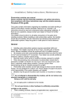
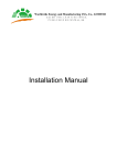
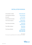
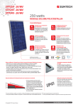
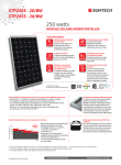
HareonSolar PV module Installation Manual Version 2013.12 CONTENTS Purpose ............................................................................................................................................ 1 Disclaimer of liability ........................................................................................................................ 1 Quality Assurance ............................................................................................................................ 2 Security and Transport ..................................................................................................................... 2 Mechanical Installation .................................................................................................................... 3 Electrical Installation ...................................................................................................................... 11 Grounding ...................................................................................................................................... 13 Bypass Diode and Block Diode ....................................................................................................... 14 Maintenance .................................................................................................................................. 14 Recycling ........................................................................................................................................ 14 PURPOSE This manual is for Hareon solar PV module (here in after referred to as Module); introduce safety and maintenance information of module installation. Please read this manual carefully before you start the installation, follow the rules strictly during the installation. DISCLAIMER OF LIABILITY Because the use of this manual and the conditions or methods of installation, operation, use and maintenance of module are beyond Hareon’s control, Hareon does not accept responsibility and expressly disclaims liability for loss, damage, or expense arising out of or in any way connected with such installation, operation, use or maintenance. No responsibility is assumed by Hareon for any infringement of patents or other rights of third parties, which may result from use of the module. No license is granted by implication or otherwise under any patent or patent rights. The information in this manual is based on Hareon’s knowledge and experience and is believed to be reliable; but such information including product specification (without limitations) and suggestions do not constitute a warranty, expresses or implied. Hareon reserve the right to change the manual, the PV produce, the specifications, or product information sheets without prior notice. 1 QUALITY ASSURANCE Hareonsolar provide 10 years ensure for materials and process of module in 10 years after module sold. 12 years ensure for 90% output, 25 years ensure for 80% output. SECURITY AND TRANSPORT Do not step on the module Do not dismantle drop the module Artificially concentrated sunlight shall not be directed on the module or panel Do not hoist on the connection boxes Do not use pointed or sharp objects with the module Do not bend the module. Use both hands Do not touch the surface of the coated glass with bare hand Ensure all connectors are kept clean and dry 2 MECHNICAL INSTALLATION Site choosing Ø Select a suitable location for installing the modules. Ø The modules should be facing south in northern latitudes and north in southern latitudes. Ø The module should not be shaded at any time. Ø Do not use modules near equipment or in locations where flammable gases may be generated or collected. Ø Without the written approval or the two sides agreed in the contract, the straight-‐line distance from the installation place to the seaside does not allow less than 1km. Ø The module to be installed under the following conditions: l Operating Temp: -‐40°~85° l Storage Temp: -‐40°~60° l Humidity:≤85% l Wind Pressure: ≤2400Pa l l Snow Pressure: ≤5400Pa Corrosion resistance: except area with salt or sulfur corrosion 3 Mounting angle Ø A string of module should be mounted at the same angle, radiation exposure differ from mounting angle, it will cause current difference, which lead to lower operating efficiency of the whole system. Ø Mounting angle please refer to table 1 table1 latitude Mounting angle 0°~15° =15° 15°~25° =Latitude 25°~30° = Latitude +5° 30°~35° = Latitude+10° 35°~40° = Latitude+15° >40° = Latitude+20° Module mounting Ø General rules l The module mounting structure must be made of durable, corrosion-‐resistant and UV-‐resistant material. l Modules must be securely attached to the mounting structure. l In regions with heavy snowfall in winter, select the height of the mounting system so that the lowest edge of the module is not covered by snow for any length of time. In addition, ensure that the lowest portion of the module is placed high enough so that it is not shaded by plants or trees or damaged by flying sand. l Provide adequate ventilation under the modules in conformity to your local regulations. A minimum distance of 10 cm between the roof plane and the frame of the module is generally recommended. l Observe the linear thermal expansion of the module frames (the recommended minimum distance between two modules is 2 cm). l Always observe the instructions and safety precautions included with the module support frames. l Do not attempt to drill holes in the glass surface or the frames of the modules as this will void the warranty. l Before installing modules on a roof, ensure that the roof construction is suitable. In addition, any roof penetration required to mount the module must be properly sealed to prevent leaks. l When installing a module on a pole, choose a pole and module mounting structure that will withstand the anticipated winds for the area. 4 Ø Installation methods Modules can be installed on the frame by the following 3 methods: l Mounting hole system: use corrosion free M8 bolt, module can be installed on the support frame through the installation holes on its own frame, show in figure1 l Clamping system: choose the right fixture to fix the module on the support frame, show in figure2 l Insertion system: Insert the whole module into the rail, show in figure3 Module Mounting structure Nut(M8, SS) Spring washer Flat washer Bolt(M8, SS) figure1 5 Nut(M8, SS) Module Spring washer Flat washer Mounting structure Clamp Bolt(M8, SS) figure2 figure3 6 l Select the proper installation method depending on the load, please refer to figure4 for details: 2400Pa l oad 3800Pa l oad 1/2 1/3 Screw f i t t i ng 1/1 5400Pa l oad 2/2 At t achment t o t he short modul e si des 3/1 100mm 100mm L 50mm L 1/4 L±50 100mm Use f our mount i ng cl i ps 3/2 3/3 Use si x mount i ng cl i ps Permi ssi bl e cl amp 1/4 B 1/4 B 100mm 1/4 B B B Short f rame use f our mount i ng cl i ps Long f rame use t wo mount i ng cl i ps Use f our mount i ng cl i ps 4/1 4/2 4/3 Permi ssi bl e cl amp I nsert i on syst em 100mm I nsert i on syst em I nsert i on syst em I nsert i on syst em Permi ssi bl e cl amp 1/4 L±50 Use f our mount i ng cl i ps Permi ssi bl e cl amp 1/4 B 2/4 Permi ssi bl e cl amp 1/4 L±50 5/9 L±50 L 1/4 L±50 1/4 L±50 Use f our mount i ng cl i ps Cl ampi ng syst em 2/3 Permi ssi bl e cl amp 1/4 L±50 Permi ssi bl e cl amp Use ei ght mount i ng hol es 50mm 2/1 L Cl ampi ng syst em At t achment t o t he l ong modul e si des Use f our mount i ng hol es I nsert i on syst em 7 2400Pa l oad 3800Pa l oad 5400Pa l oad 5/2 5/3 Screw f i t t i ng 5/1 6/1 At t achment t o t he l ong modul e si des Cl ampi ng syst em Use f our mount i ng hol es 6/2 Permi ssi bl e cl amp 1/4 L±50 1/4 L±50 50mm 1/4 L±50 Permi ssi bl e cl amp 100mm 100mm 1/4 L±50 Use f our mount i ng cl i ps 7/2 7/3 100mm L L Use f our mount i ng cl i ps Permi ssi bl e cl amp 6/4 Permi ssi bl e cl amp 50mm Use si x mount i ng cl i ps Permi ssi bl e cl amp B 1/4 B 1/4 B B 1/4 B 100mm 1/4 B Cl ampi ng syst em 1/4 L±50 5/9 L±50 L Use f our mount i ng cl i ps At t achment t o t he short modul e si des 6/3 Permi ssi bl e cl amp 1/4 L±50 L 7/1 Use ei ght mount i ng hol es Short f rame use f our mount i ng cl i ps Long f rame use t wo mount i ng cl i ps Use f our mount i ng cl i ps 8/1 8/2 8/3 I nsert i on syst em I nsert i on syst em I nsert i on syst em figure4 Note:The module has passed the IEC61215 mechanical 2400Pa and 5400Pa on existing 8 installing holes. 8 Ø Module Specification(show in figure5 and table2) Drai nage hol es 8-9×14 M ount i ng hol es A E B + - F A 2-Φ4 Ground hol es C 1/2 B A-A G A C D Front View Si de Vi ew Back Vi ew figure5 9 H Frame Sect i on table2 unit:mm No. Module Type A B C D E F G H weight Application (kg) class Maximum Series Fuse (A) HR-‐XXX-‐24/Aa 1 HR-‐XXX-‐24/Aa-‐1 808 1580 40 758 800 1300 10 35 15.8 Class A 15 808 1580 40 758 800 1300 10 35 15.8 Class A 15 1068 1580 50 1018 800 1300 11 35 20 Class A 15 992 HR-‐XXX-‐24/Aap 2 HR-‐XXX-‐24/Aab 3 HR-‐XXX-‐32/Az HR-‐XXXP-‐18/Bb 4 HR-‐XXXP-‐18/Bb-‐1 HR-‐XXXP-‐18/Bbp 5 HR-‐XXXP-‐18/Bbb HR-‐XXX-‐18/Cb 6 HR-‐XXX-‐18/Cb-‐1 HR-‐XXX-‐18/Cbp 7 HR-‐XXX-‐18/Cbb HR-‐XXXP-‐24/Ba 8 HR-‐XXXP-‐24/Ba-‐1 HR-‐XXXP-‐24/Bap 9 HR-‐XXXP-‐24/Bab HR-‐XXX-‐24/Ca 10 HR-‐XXX-‐24/Ca-‐1 HR-‐XXX-‐24/Cap 1636 40 942 856 1356 10 35 19.3 Class A 15 1000 1662 45 950 856 1356 10 35 20 Class A 15 992 1636 40 942 856 1356 10 35 19.3 Class A 15 1000 1662 45 950 856 1356 10 35 20 Class A 15 992 1636 40 942 856 1356 10 35 19.3 Class A 15 1000 1662 45 950 856 1356 10 35 20 Class A 15 992 1636 40 942 856 1356 10 35 19.3 Class A 15 1000 1662 45 950 856 1356 10 35 20 Class A 15 992 1952 40 942 856 1356 10 35 21.8 Class A 15 1000 1982 50 942 856 1356 11 35 23.5 Class A 15 992 1952 40 942 856 1356 10 35 21.8 Class A 15 1000 1982 50 942 856 1356 11 35 23.5 Class A 15 992 1952 40 942 856 1356 10 35 21.8 Class A 15 1000 1982 50 942 856 1356 11 35 23.5 Class A 15 992 1952 40 942 856 1356 10 35 21.8 Class A 15 1000 1982 50 942 856 1356 11 35 23.5 Class A 15 11 HR-‐XXX-‐24/Cab 12 HR-‐XXXP-‐18/Ebb 992 1636 45 942 856 1356 10 35 19.5 Class A 15 13 HR-‐XXXP-‐24/Eab 992 1952 50 942 856 1356 11 35 23 Class A 15 992 1636 45 942 856 1356 10 35 19.5 Class A 15 992 1952 45 942 856 1356 11 35 23 Class A 15 14 15 HR-‐XXXP-‐18/Db HR-‐XXXP-‐18/Dbp HR-‐XXXP-‐24/Da HR-‐XXXP-‐24/Dap 16 HR-‐XXXP-‐18/Dbb 992 1636 45 942 856 1356 11 35 19.5 Class A 15 17 HR-‐XXXP-‐24/Dab 992 1952 45 942 856 1356 11 35 23 Class A 15 18 HR-‐XXXP-‐36/HBb 1016 1625 45 966 856 1356 10 35 19.8 Class A 15 990 NA NA 20 Class A 20 TM 19 SCHOTT PERFORM POLY xxx TM SCHOTT POWER POLY xxx TM SCHOTT PERFORM MONO xxx 1652 35 Note:“XXX”refer to power index 10 NA 11.8 16.4 ELECTRICAL INSTALLATION DC power generated by PV system can be converted to AC power, connected to the Grid. Policies to the Grid connected renewable energy system vary from region to region. Please turn to senior system design engineer for relevant information before you start to design the PV system. Usually, you should get a formal approval from local public utilities sector before you start it. General Rules Ø Installation structure should be compatible with Aluminum frame of module, in order to avoid galvanic corrosion. Ø Negative grounding is recommended during installation of Module to prevent PID effect Ø Positive and negative part of the module should use the same type of connector for electrical connection. Ø Do not allow non-‐professionals to open the lock nut of the connector, in order to avoid connector leakage. Ø Ensure the connectors keep clean, dry and connected sufficiently (hear a “click” meaning connecting sufficiently), otherwise it will cause the connectors burned or fire because of the arc ignition. Ø All electrical components should have ratings equal or greater to the system rating. Do not exceed the maximum allowable system, voltage as listed on the module label. Ø Under normal conditions, a photovoltaic module is likely to experience conditions that produce more current and/or voltage than reported at standard test conditions. Accordingly, the values of ISC and Voc marked on this module should be multiplied by a factor of 1.25 when determining component voltage ratings, conductor current ratings, fuse sizes, and size of controls connected to the PV output. Ø To prevent discharge in the process of dismantling conductor, you must use an opaque material to completely cover the modules Ø PV system only installed by certified professionals, module can generate a current under light, non-‐professionals not familiar with safety regulations may be subject to the risk of electric shock, etc. Ø Always use the same type of module in a PV system. While connected in series, voltage of each string should below maximum system voltage (show in figure6).Recommended maximum series module configurations: 1000 V/ (1.25*Voc). Ø While connected in parallel, the output current is equal to the sum of current of each string (show in figure7). Use a fuse in each string of module; please refer to the application requirements locally. Recommended maximum parallel module configurations: Fuse rating/Isc+1. figure6series figure7 Parallel 11 Ø Please refer to local regulations to determine the system wires size, type and temperature. Ø The cross section area of cable and the capacity of connector must be selected to suit the maximum system short circuit current(Recommended cross section area of cable is 4mm2 for a single module and rated current of a connector is larger than 10A ), otherwise the cable and connector will be overheated under large current. Please pay attention: the temperature limit of Ø cables is 85℃ and the temperature limit of connector 105℃. During the installation, make sure the connectors, inverters and other electrical components in a disconnected. Ø In order to reduce lightning damage, keep the loop as small as possible while laying cable. Recommended that each string using the fuse protection device. 12 GROUNDING Ø Grounding Lug with Machine Screw at Mounting Hole l All frame and mounting structure are required to grounding In accordance with the National Electrical Code. l While using mental structure, please make sure its surface have been electroplating treated, in order to keep a good conducting circuit. l Choose a proper grounding conductor, connecting frame with the mounting structure, effectively grounding. l Grounding conductor must be connected to ground via a suitable ground electrode. Lugs recommended. Mounting frame should also be grounding without bolts and nuts electrically connecting to module frame. l Striping the grounding wire to proper length, do not hurt the metal core during; insert it into the lug, fastening the screw then. Follow figure8 use bolt to connect lug to the frame. Recommended M3 screw assembly is 2.3 N·m. Nut(M3, SS) Spring washer Flat washer star washer Frame Bolt(M3, SS) Grounding lug Grounding wire Figure 8 Ø Grounding wire with Machine Screw at Mounting Hole l A grounding screw assembly must be attached at a designated grounding holes location using only stainless steel hardware. Insert a #6 stainless steel screw first through spring washer, flat washer, cup washer with a 2.1mm diameter copper wire, star washer, and then through the grounding hole on the frame, flat washer, spring washer, at last tighten them with the #6 nut, Please pay attention: the temperature limit of conductor is 85℃, show in figure9. Nut(#6,SS) Spring washer(SS) Flat washer(SS) star washer(SS) Frame Flat washer(SS) Cup washer(SS) Spring washer(SS) Copper wire Bolt(#6,SS) Figure9 13 BYPASS DIODE AND BLOCK DIODE In system with more than 2 strings of module, while one module shaded and others under light, overload Isc will cause overheat of cell to damage the module. By-‐pass diodes are required to protect each string of the module from the effect of shading. Do not try to open the j-‐box by yourself to change diode even if it breaks down, turn to professionals for help. Blocking diodes are used between battery and module to prevent damage on module while discharge. MAINTENANCE Module under normal circumstances no maintenance. Here we recommend the following maintenance methods to ensure the best performance of module: Ø In most conditions, the rain can be enough to keep the glass clean. Ø Clean the glass surface of the module when required. Always use clean water and a soft sponge or cloth for cleaning. A mild, non-‐abrasive cleaning agent or alcohol may be used to remove stubborn dirt. Ø Do not try to clean a module with broken glass or perforated backsheet; it will cause serious electrical shock. Ø Regulation inspection every 6 month for grounding, mechanical and electrical connections. Make sure all connectors clean, reliable, no damage or corrosion happened. Ø When maintenance personnel to open the connector, we need to check whether the parts of the connector is OK, or else the connector must be replaced, the damaged connector will cause leak, the nut tightening torque requirements: 1.5N • m-‐3 N • m. Ø You must use an opaque material to completely cover the module during maintenance. If you need electrical or mechanical inspection or maintenance, it is recommended to have a licensed, authorized professional carry out the job to avoid hazards of electric shock or injury. Warning: Before any electrical maintenance, you should firstly shut down the system; any improper maintenance can lead to electric shock or injury. RECYCLING As a member of PV CYCLE,Hareonsolar promise after module has been out of use, it will be recycled by specialized organizations to ensure all over the PV process is environment friendly. All service items are compliance with CE, providing free terminal service also (except accidents occurring during the installation) To get more information please visit: http://www.pvcycle.org/ 14 Jiangyin Hareon Power Co., Ltd. Address:Huangtang Industrial Zone, Xuxiake Town, Jiangyin, Jiangsu, P.R. China, 214407 Tel:+86(510)8653 0222 Fax:+86(510)8653 0828 E-‐mail:[email protected] www.hareonsolar.com